
Parts Diagrams
Exploded views and component parts lists from the service manual — 177 diagrams across 12 sections, 1577 individual parts
Engine (K8)
B211 diagrams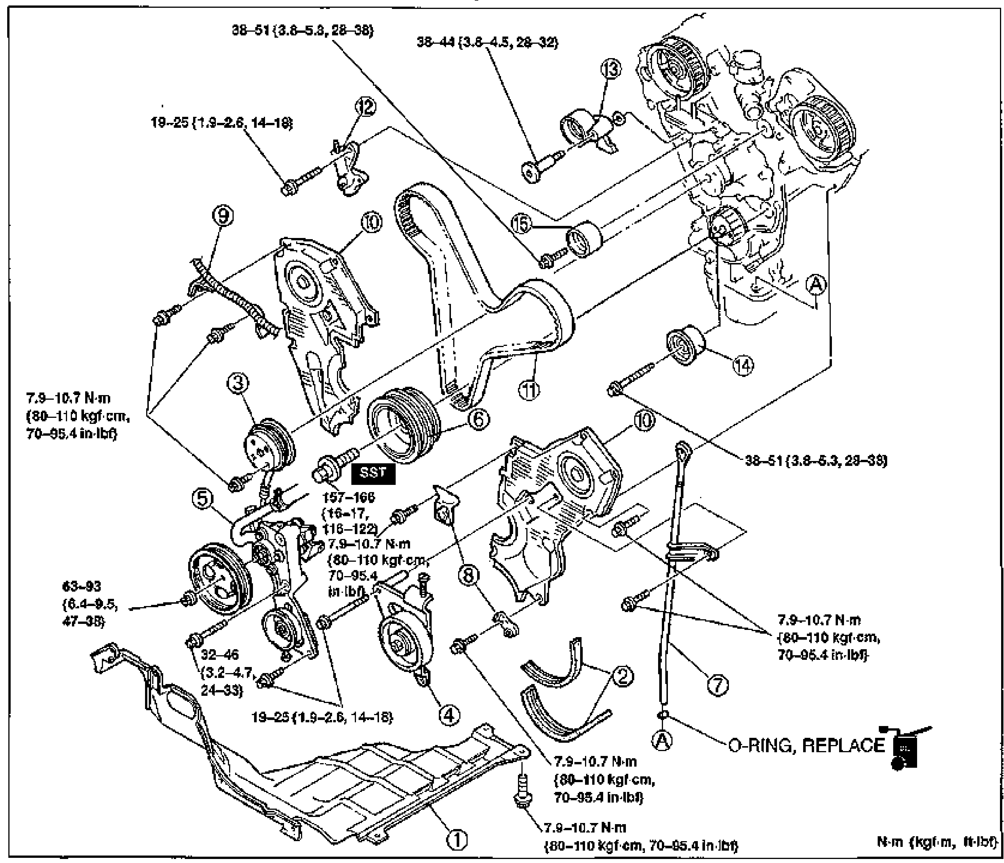
TIMING BELT
B2-13Exploded view of the timing belt assembly and front engine covers (K8-ZE V6). Numbered balloon callouts 1-15 identify components in removal order, with tightening-torque annotations in N·m {kgf·cm/kgf·m, in-lbf/ft-lbf} at each fastener. An 'SST' label marks the crankshaft pulley holder location, and 'O-RING, REPLACE' is noted near the dipstick pipe (point A).

ON-VEHICLE MAINTENANCE
B2-24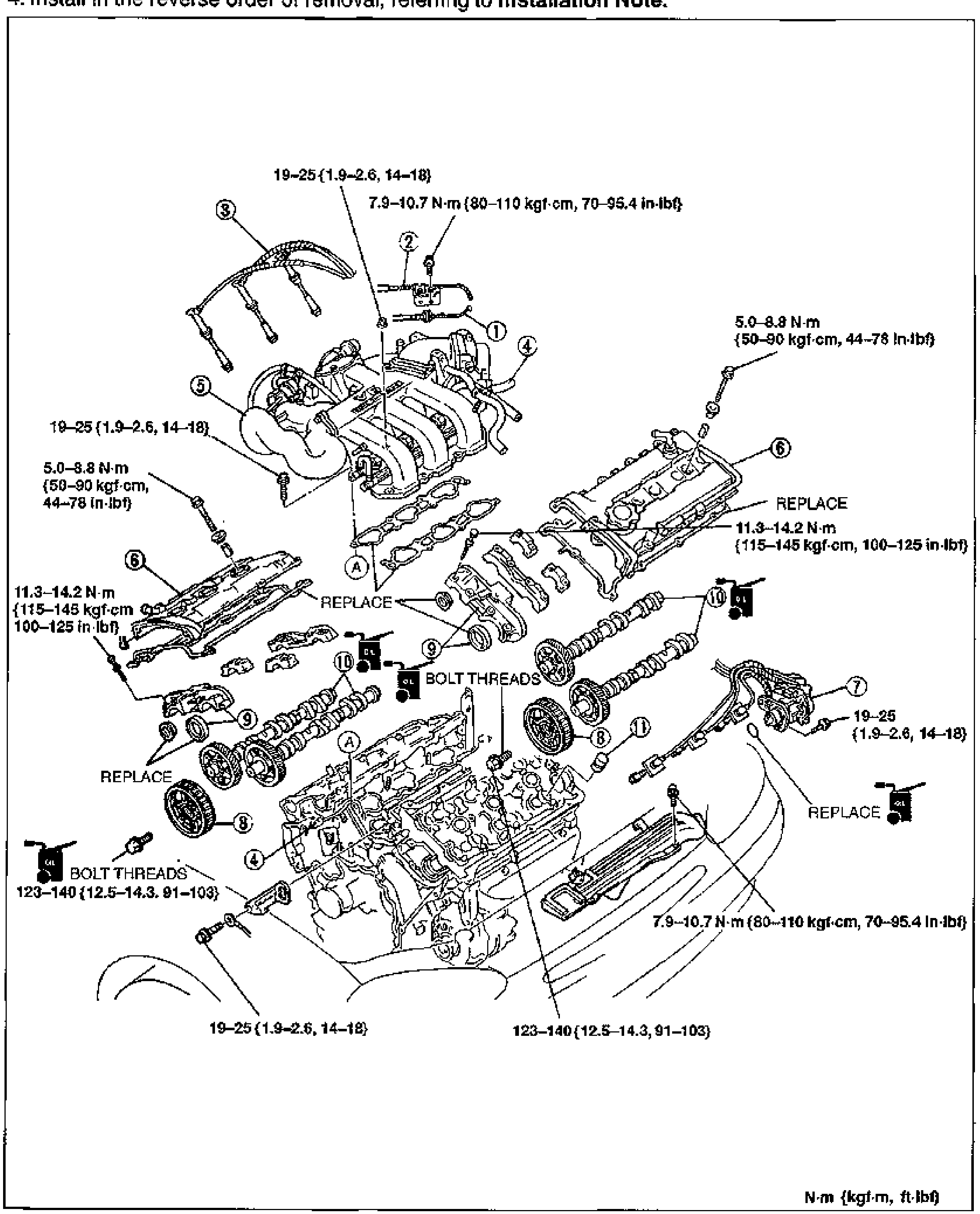
ON-VEHICLE MAINTENANCE — HLA Removal / Installation
B2-37Exploded view of the V6 cylinder head / HLA components with numbered balloon callouts 1 through 11 and torque-spec callouts. Shows spark plug wires, intake manifold, gaskets (REPLACE), cylinder head covers, camshafts, camshaft pulleys, and HLAs. BOLT THREADS and oil-application icons mark fastener prep points. Torque specs annotated throughout.
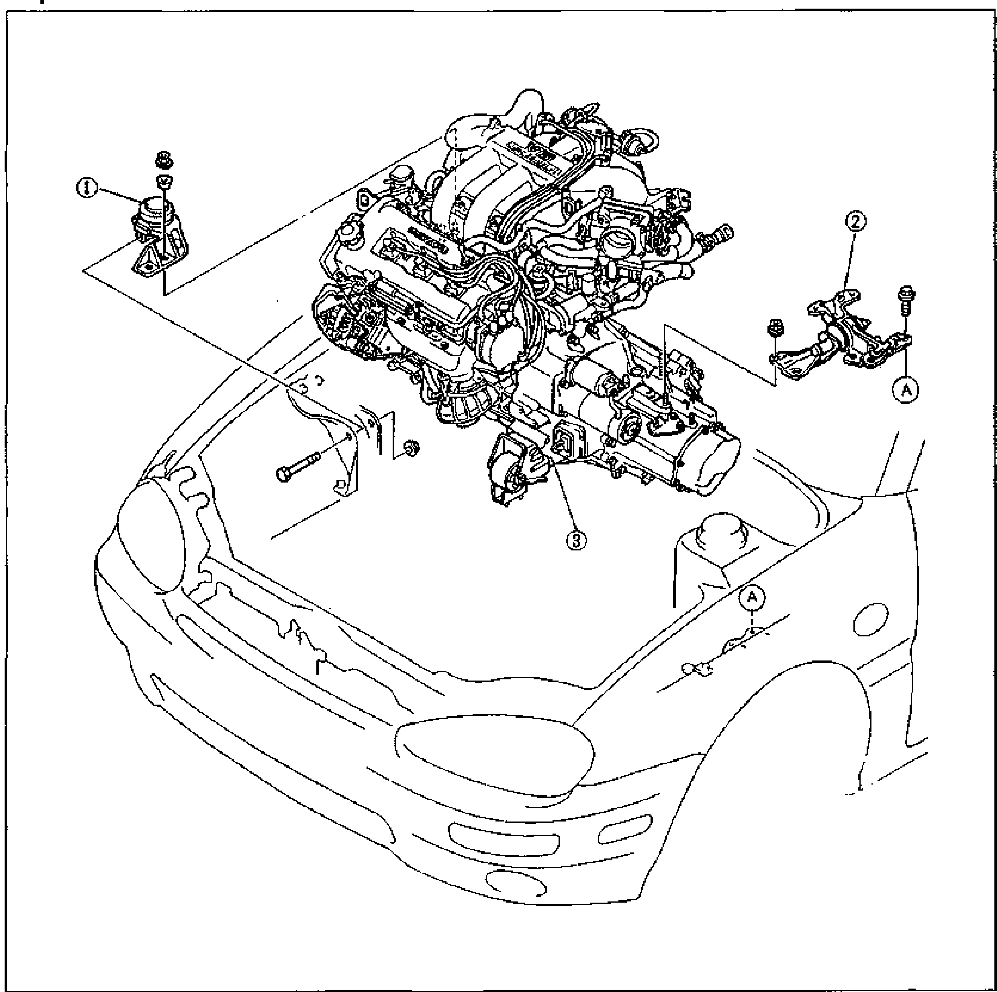
Removal — Step 5 (Engine and Transaxle Assembly)
B2-50Step 5 exploded view of the engine and transaxle assembly being lifted out of the front engine compartment of the MX-3. Shows the V6 engine/transaxle unit above the front body. Callout 1 points to the No.3 engine mount rubber at left; callout 2 points to the No.4 engine mount rubber and bracket at right (with reference letter A); callout 3 points to the engine and transaxle assembly. A second reference letter A is shown on the body near the right fender.
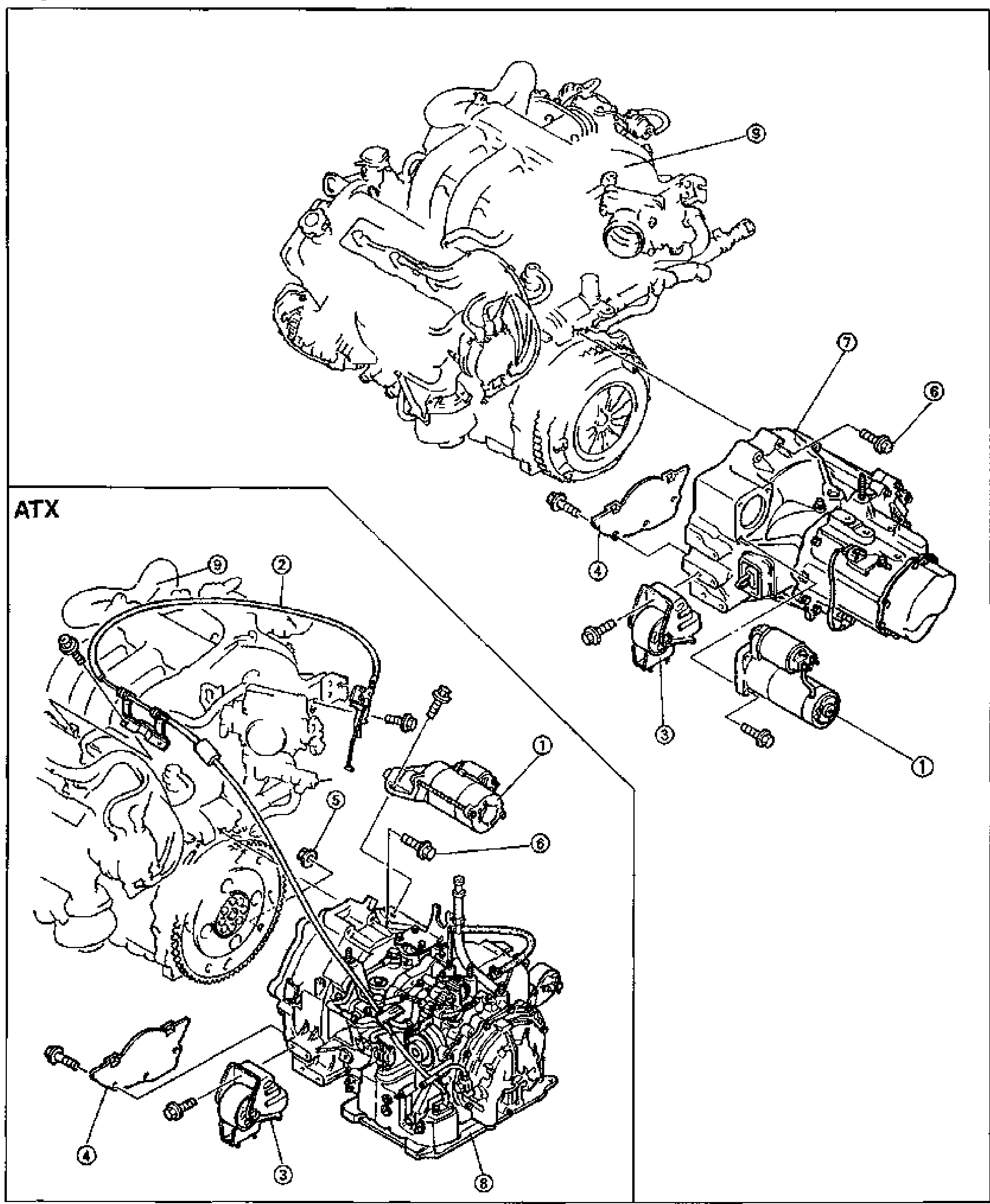
Removal — Step 6 (Engine / Transaxle Separation)
B2-51Step 6 exploded view separating the engine assembly from the transaxle. Upper portion shows the V6 engine (callout 9) joined to the manual transaxle (MTX, callout 7) with starter, seal plate (4), transaxle mounting bolts (6) and No.2 engine mount rubber and bracket (3). The lower-left inset boxed 'ATX' shows the automatic transaxle (ATX, callout 8) variant with engine, throttle cable (2), torque converter nuts (5), starter (1), seal plate (4) and No.2 engine mount rubber and bracket (3).
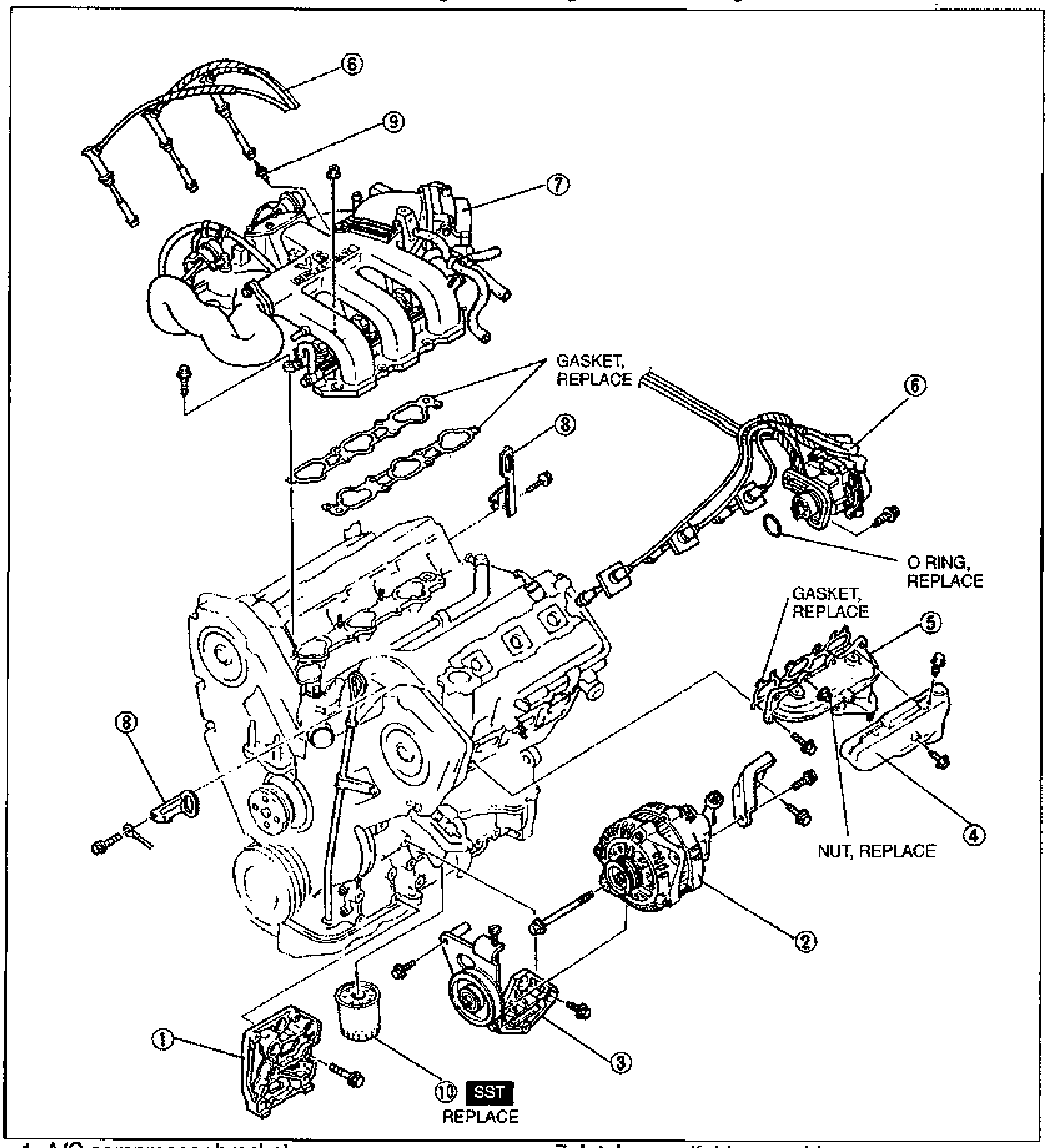
Disassembly — Auxiliary Parts
B2-58Exploded view of the engine auxiliary parts to be disassembled in numbered order. Shows the intake manifold assembly (7), spark plugs (9), distributor and high-tension lead (6), engine hangers (8), generator (2), bracket and tensioner (3), exhaust manifold LH (5) with insulator LH (4), oil filter (10), A/C compressor bracket (1). Gaskets and O-ring are marked REPLACE; nut marked REPLACE; oil filter marked SST / REPLACE.
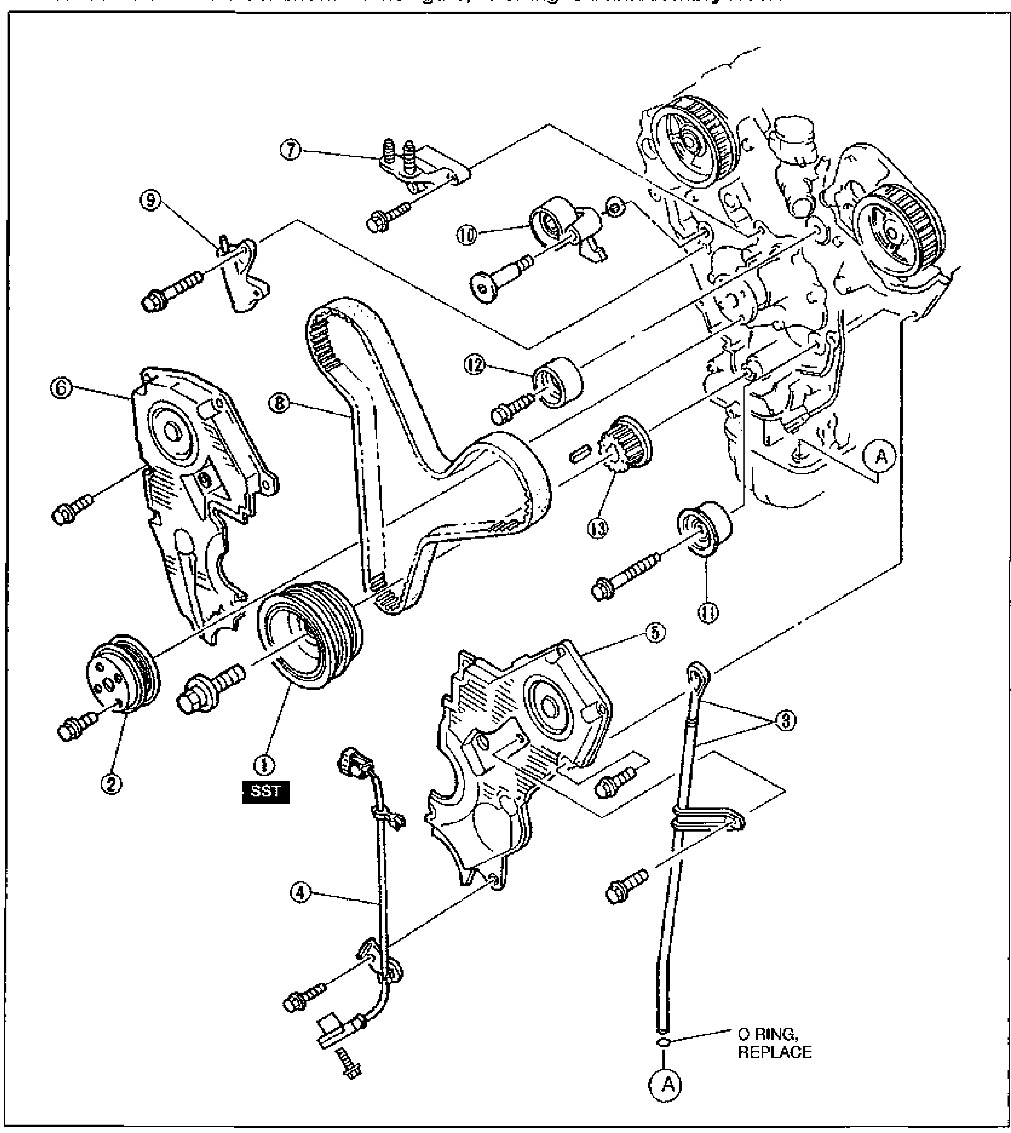
TIMING BELT
B2-60Exploded view of the K8 V6 timing belt assembly showing disassembly order. Numbered balloon callouts identify: crankshaft pulley, water pump pulley, dipstick and pipe, crankshaft position sensor, timing belt covers (LH/RH), No.3 engine mount bracket, timing belt, auto tensioner, tensioner pulley, idler pulleys, and timing belt pulley. An SST is shown at the crankshaft pulley, and an O-ring (replace) is called out at point A on the dipstick.
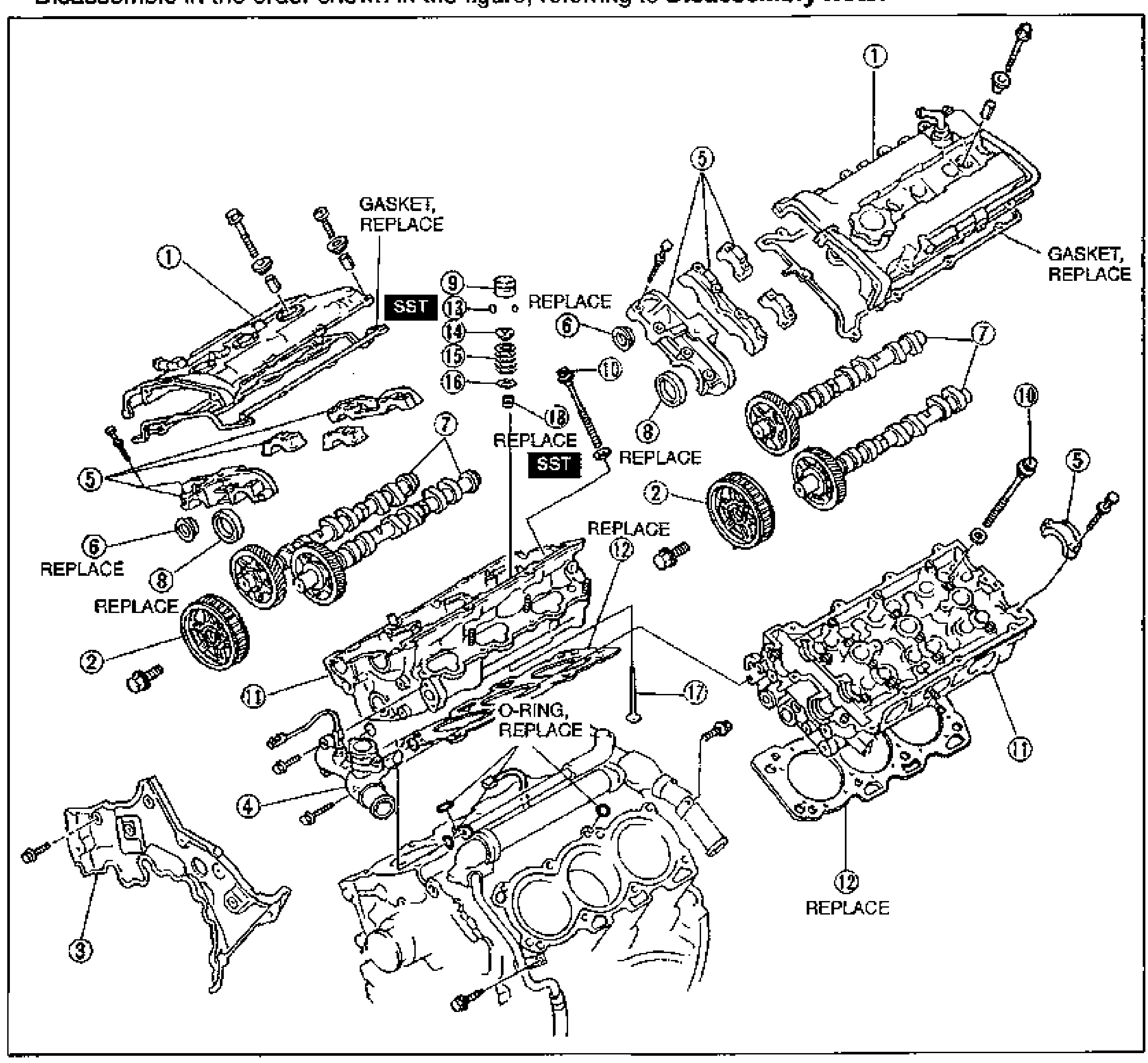
CYLINDER HEAD
B2-62Exploded view of the K8 V6 cylinder head assembly showing disassembly order with numbered balloon callouts 1-18. Both cylinder heads, camshafts, camshaft pulleys, caps and the cylinder block are shown. Multiple parts are marked REPLACE: cylinder head cover gaskets, camshaft oil seals, blind cap, valve seal, O-ring, and cylinder head gasket. Two SST labels appear near the camshaft caps/valve area.
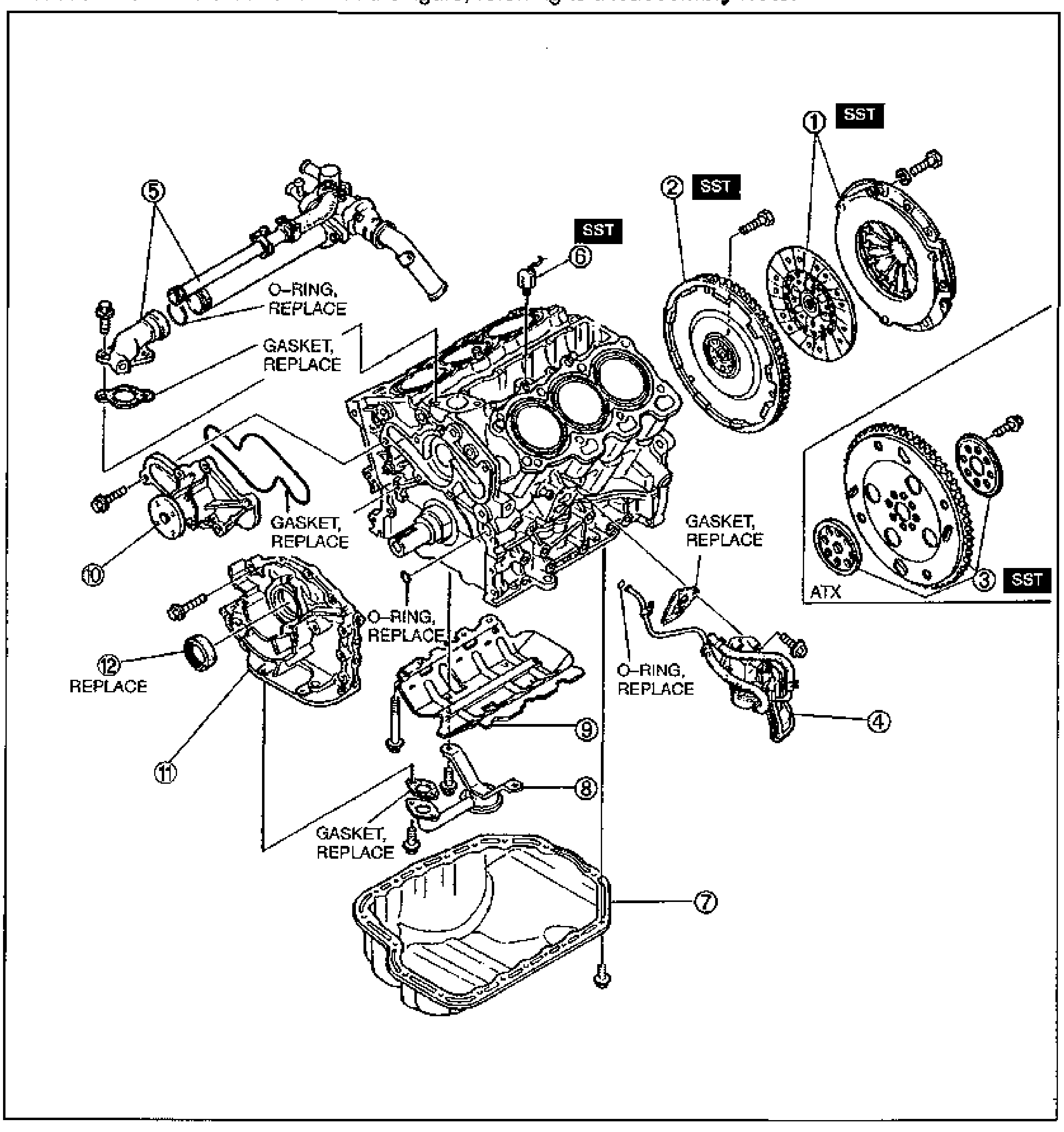
CYLINDER BLOCK (EXTERNAL PARTS)
B2-66Exploded view of the K8 V6 cylinder block external parts in disassembly order, with numbered balloon callouts 1-12. Shows clutch cover/disc and flywheel (MTX) with SST, backing plate/drive plate/adapter (ATX) with SST, knock sensor, oil cooler/filter body, water pipe and thermostat housing, oil pan, oil strainer, oil baffle, water pump, oil pump and front oil seal. Several O-rings and gaskets are marked REPLACE.
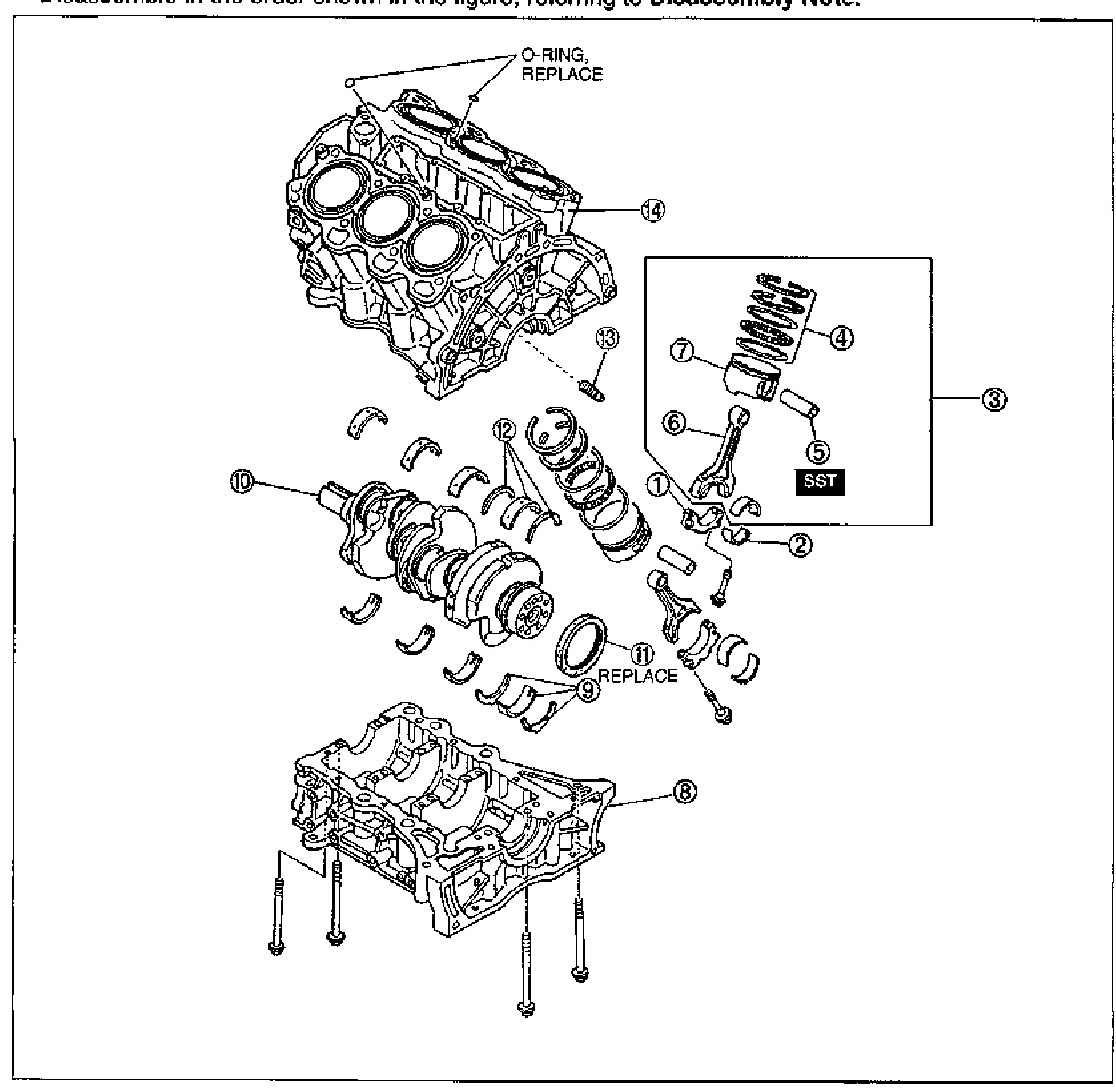
CYLINDER BLOCK (INTERNAL PARTS)
B2-69Exploded view of the K8 V6 cylinder block internal parts in disassembly order, numbered balloon callouts 1-14. Shows upper cylinder block, crankshaft, piston and connecting rod assembly (with piston ring, piston pin, connecting rod, connecting rod cap and bearings - boxed as assembly 3 with SST), main bearings and thrust bearings, rear oil seal (REPLACE), oil jet and lower cylinder block. O-rings on the block top are marked REPLACE.
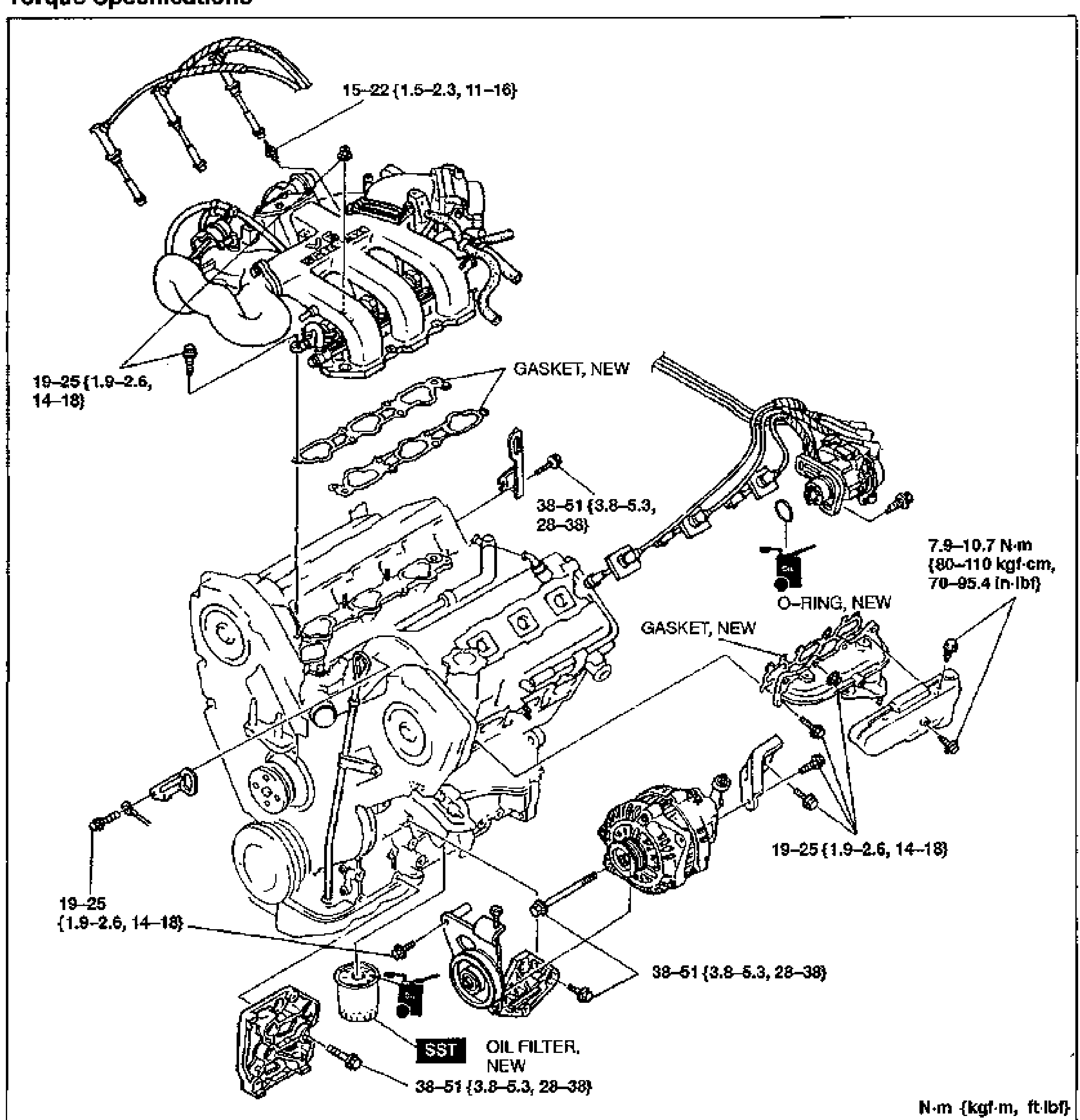
ASSEMBLY — AUXILIARY PARTS
B2-112Large exploded view of the K8-ZE V6 engine auxiliary parts showing torque specifications. Components include spark plug wires/ignition coil area, intake manifold with new gaskets, alternator, oil filter and oil filter base/bracket, O-ring, and various brackets. Torque values are called out with leader lines: '15—22 {1.5—2.3, 11—16}' for the upper bolts, '19—25 {1.9—2.6, 14—18}' (multiple locations), '38—51 {3.8—5.3, 28—38}' (multiple locations), and '7.9—10.7 N·m {80—110 kgf·cm, 70—95.4 in·lbf}'. Labels 'GASKET, NEW', 'O-RING, NEW', 'OIL FILTER, NEW', and 'SST' appear. Unit note bottom-right: 'N·m {kgf·m, ft·lbf}'.
Lubrication System (K8)
D24 diagrams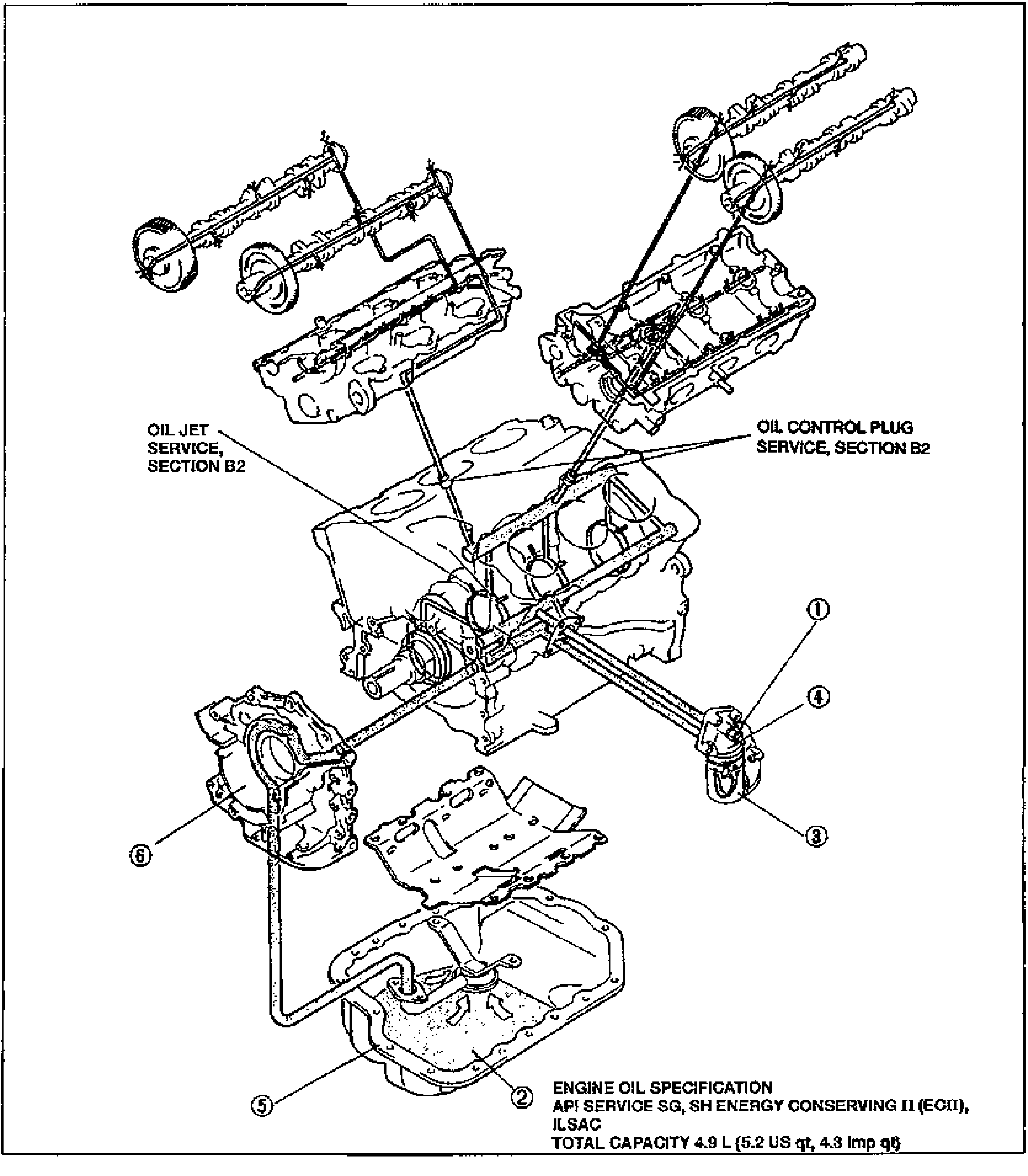
INDEX
D2-2Large exploded view of the K8 V6 lubrication-system components mounted on the cylinder block, with numbered balloon callouts. Shows both cylinder heads/camshafts at top, the engine block in the center, the oil pump/front cover at left, the oil pan at bottom, and the oil filter/cooler assembly at right. Leader labels point to OIL JET SERVICE, SECTION B2 and OIL CONTROL PLUG SERVICE, SECTION B2. An engine-oil specification note sits at lower right.
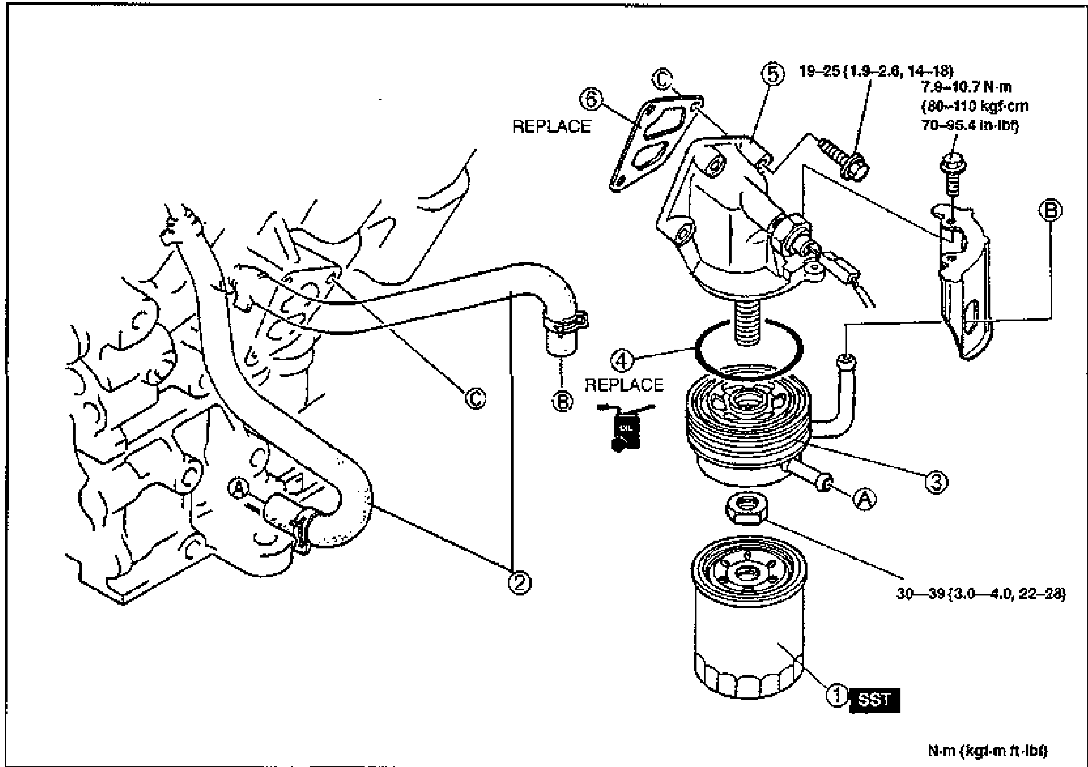
OIL COOLER
D2-7Exploded view of the oil cooler assembly with numbered balloon callouts 1-6 and torque/REPLACE annotations. Shows the oil cooler hoses routed from the engine block (A, B, C connection points), the oil filter body, oil cooler, O-ring, gasket and the spin-on oil filter at the bottom. Torque values are noted at the bolts.
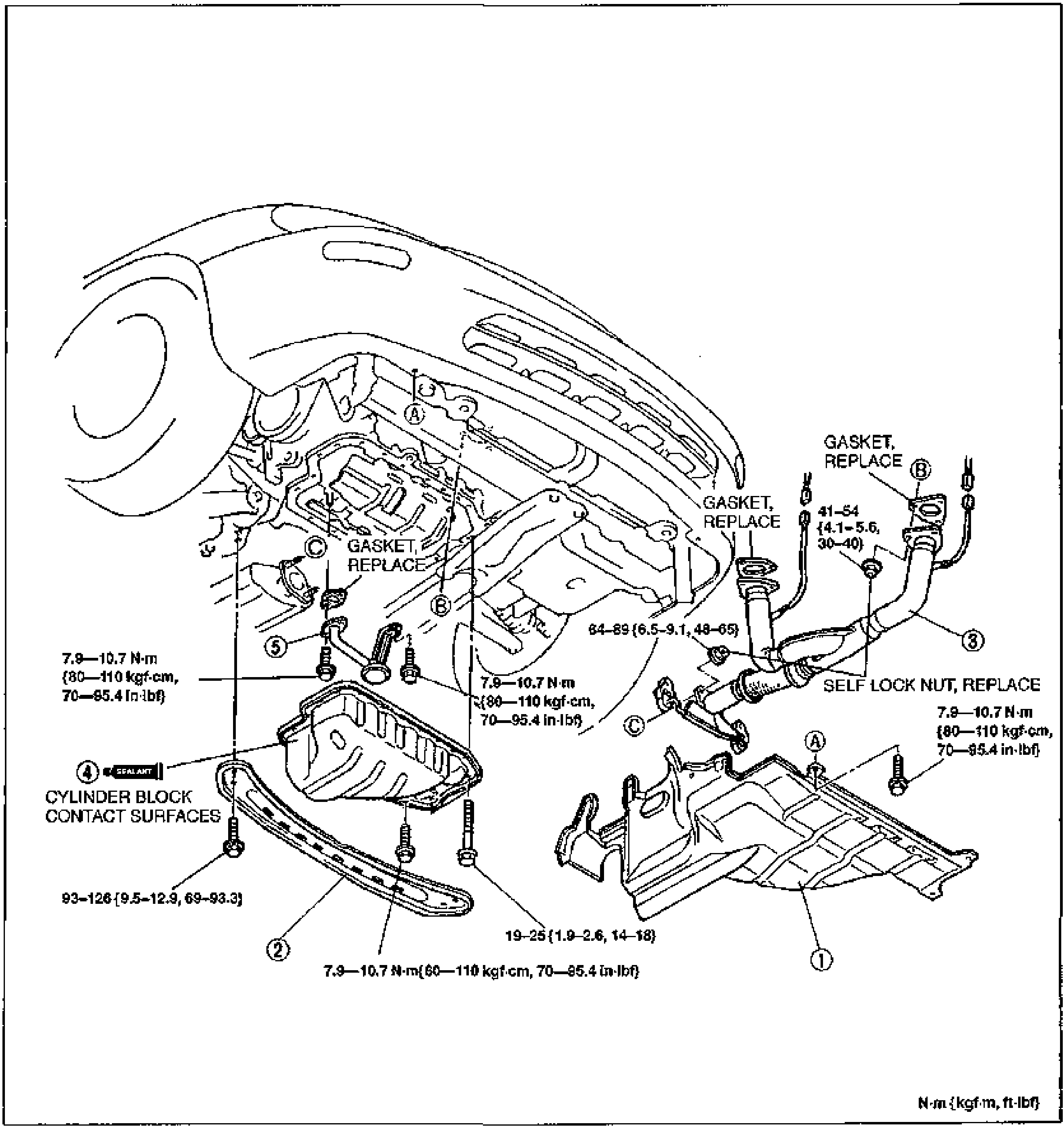
OIL PAN
D2-8Exploded view of the oil pan removal/installation on the K8 V6, with numbered balloon callouts 1-5 and torque/REPLACE/SEALANT annotations. Shows the splash shield (1), transverse member (2), front exhaust pipe (3) with gaskets and self-lock nut, oil pan (4) with sealant on cylinder block contact surfaces, and oil strainer (5). Connection points A, B, C and several torque values are noted at the bolts.
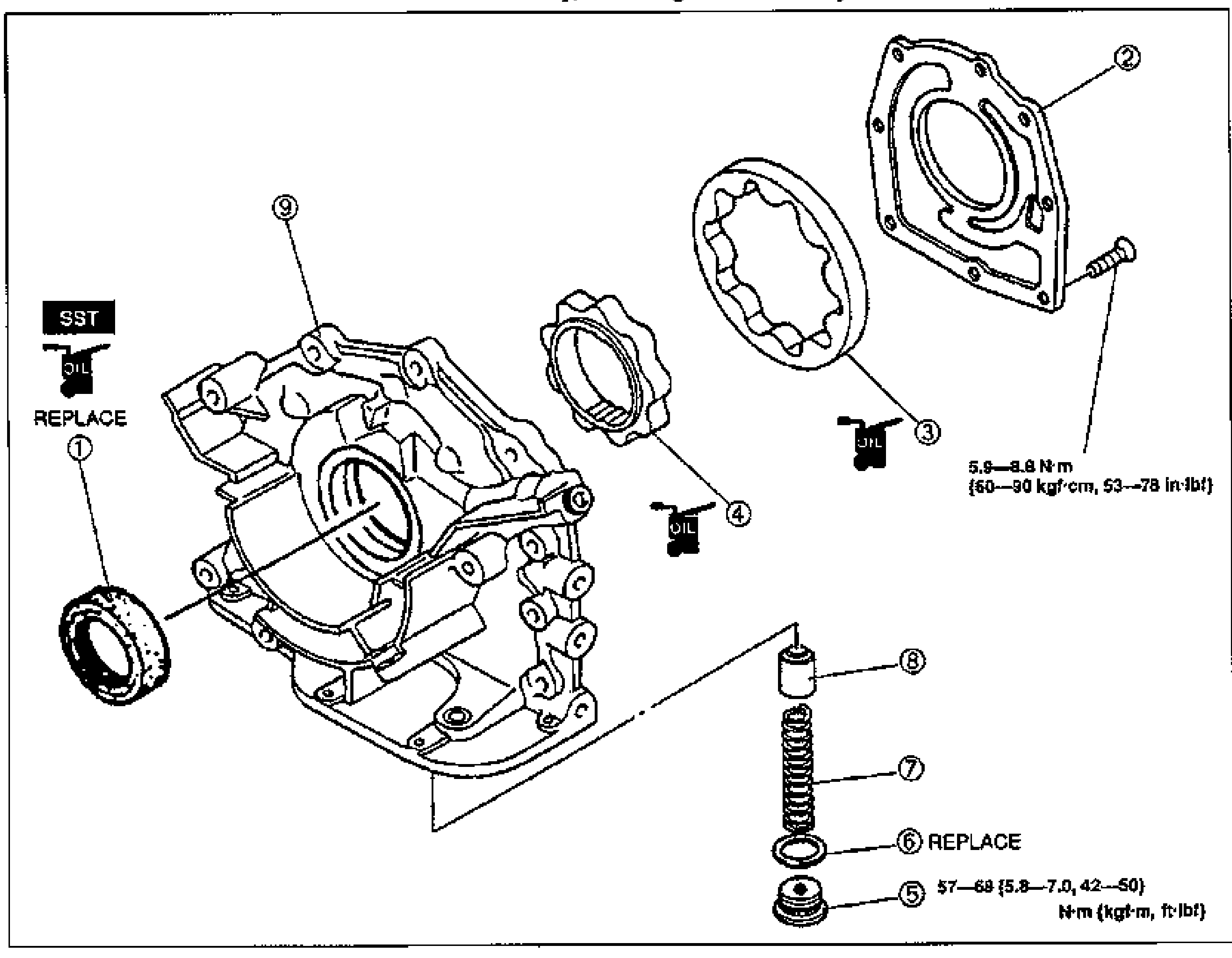
OIL PUMP
D2-11Exploded view of the oil pump assembly with numbered balloon callouts 1-9. Shows the oil seal (1, marked SST/REPLACE), pump cover (2), outer rotor (3), inner rotor (4), blind plug (5), spring seat (6, REPLACE), pressure spring (7), control plunger (8), and pump body (9). 'OIL' apply-oil symbols mark several mating surfaces. Tightening torque callouts: pump cover bolts 5.9-8.8 N·m {60-90 kgf·cm, 53-78 in·lbf}; blind plug 57-69 {5.8-7.0, 42-50} N·m {kgf·m, ft·lbf}.
Cooling System (K8)
E24 diagrams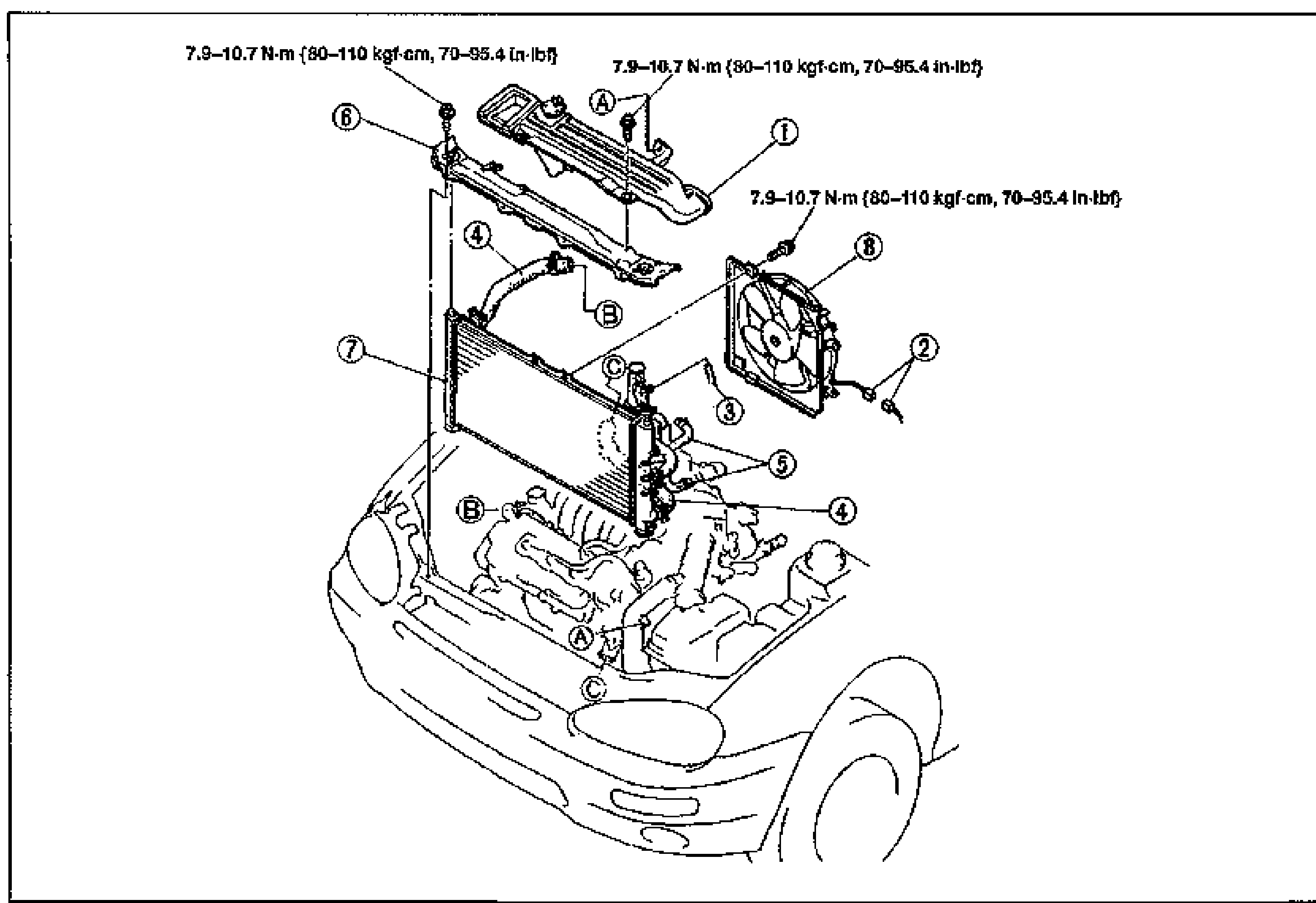
RADIATOR
E2-7Exploded view of the radiator and coolant fan assembly installed in the engine bay, shown above a phantom outline of the front of the MX-3 with the engine. Numbered balloon callouts 1-8 identify removal components, with lettered callouts A/B/C marking hose/bolt locations and torque-spec leader lines.
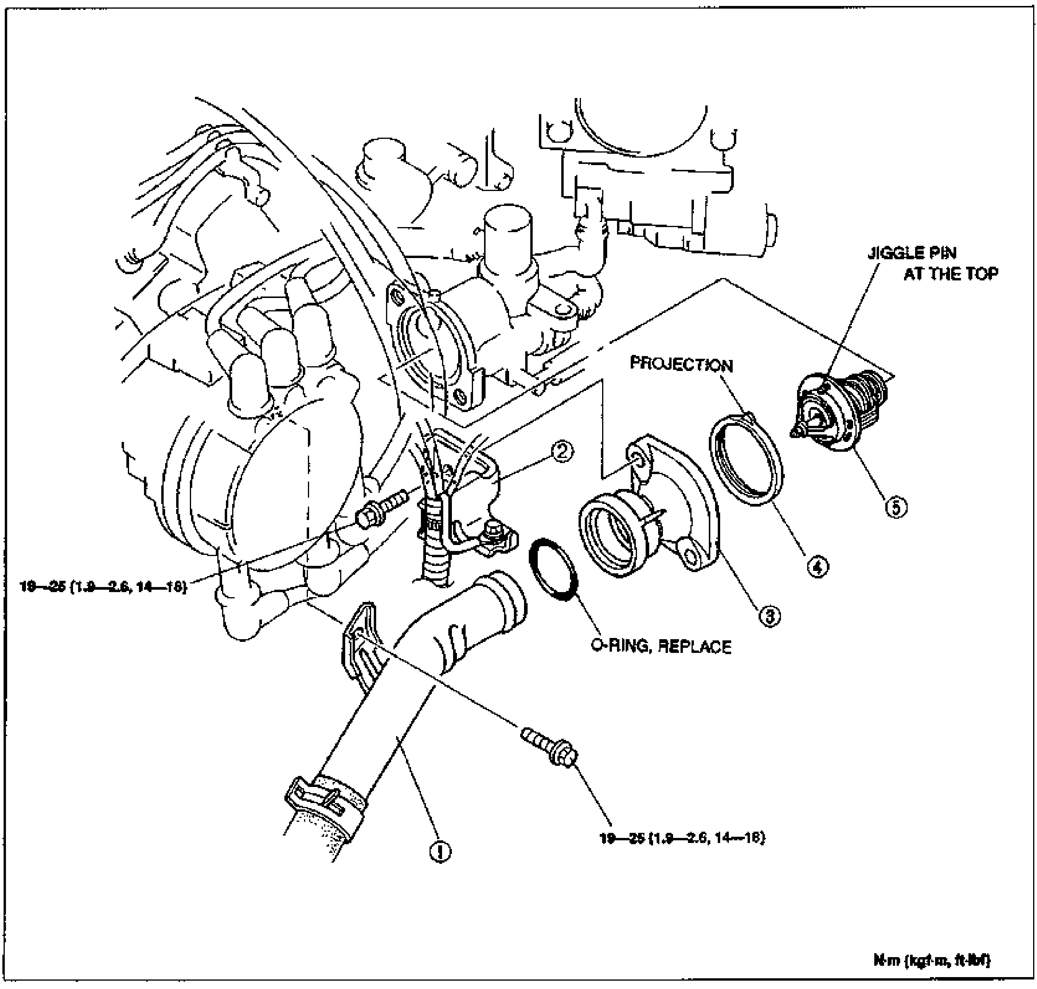
THERMOSTAT
E2-8Exploded view of the thermostat and water inlet on the engine. Numbered balloon callouts 1-5 identify the water inlet pipe, engine harness bracket, thermostat cover, thermostat gasket, and thermostat. Notes call out 'JIGGLE PIN AT THE TOP' and 'PROJECTION' on the thermostat, and 'O-RING, REPLACE' near the gasket. Two bolt torque leader lines read 19-25 N·m {1.9-2.6 kgf·m, 14-18 ft-lbf}.
WATER PUMP
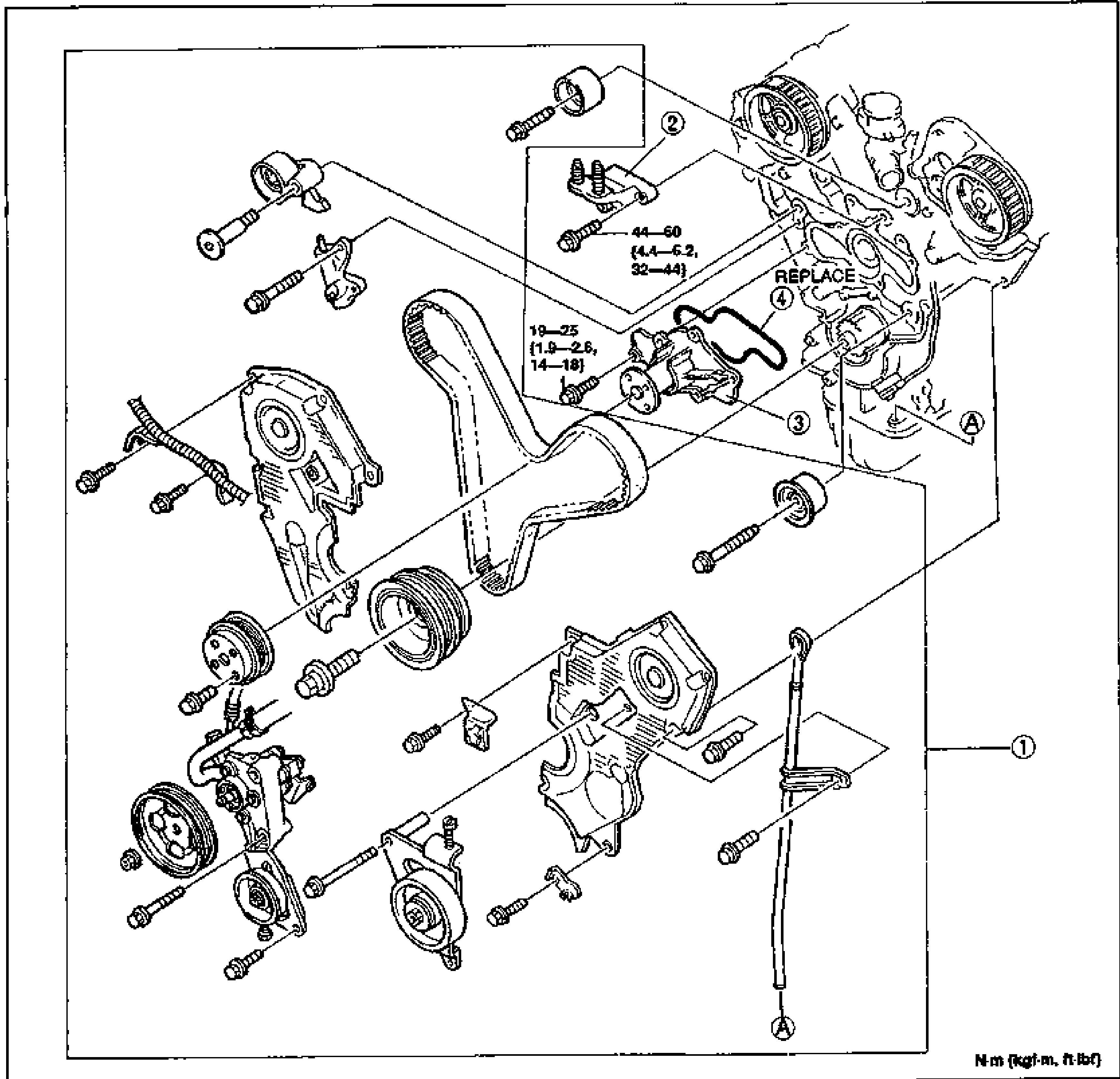
E2-10Large exploded view of the water pump and surrounding timing-belt/cover components at the front of the engine. Numbered balloon callouts 1-4 identify the timing belt, No.3 engine mount bracket, water pump assembly, and water pump rubber seal. A 'REPLACE' label points to the water pump seal/gasket. Bolt torque leader lines read 44-60 N·m {4.4-6.2 kgf·m, 32-44 ft-lbf} and 19-25 N·m {1.9-2.6 kgf·m, 14-18 ft-lbf}. Lettered references A mark mating/orientation points.
COOLANT FAN MOTOR
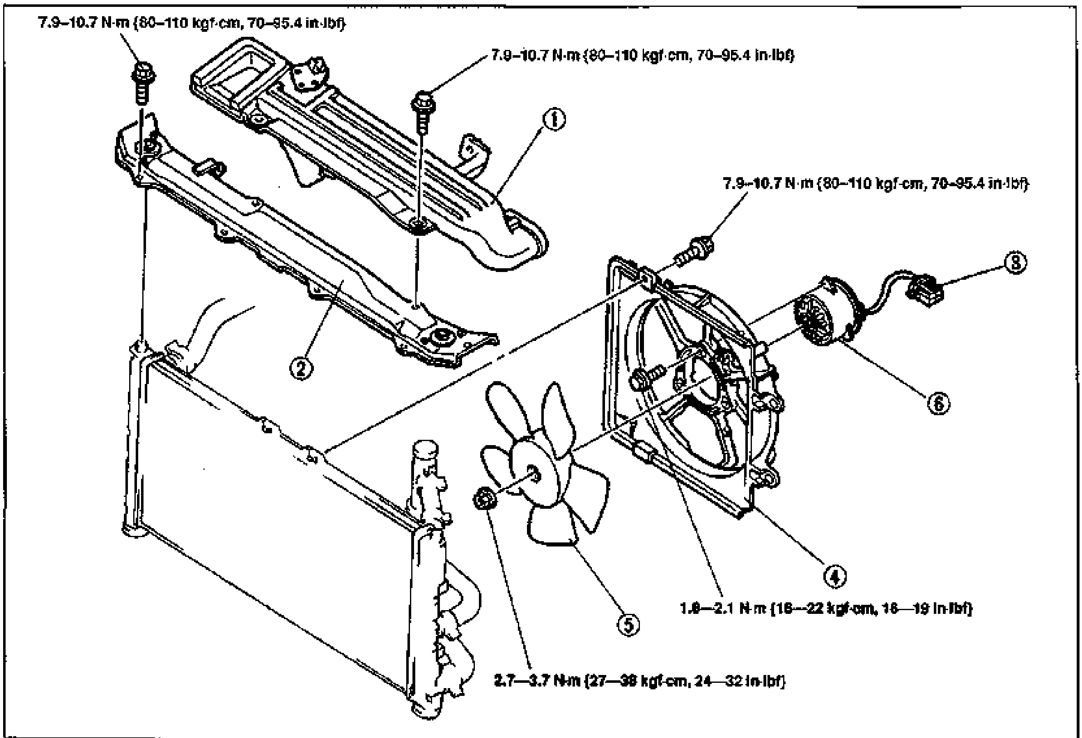
E2-13Exploded view of the coolant fan motor assembly and radiator cowling. Numbered balloon callouts identify the fresh-air duct (1), shroud upper panel (2), coolant fan connector (3), radiator cowling (4), coolant fan blade (5), and coolant fan motor (6), with the motor connector at far right. Bolt torque leader lines read 7.9-10.7 N·m {80-110 kgf·cm, 70-95.4 in-lbf}, 1.8-2.1 N·m {18-22 kgf·cm, 16-19 in-lbf}, and 2.7-3.7 N·m {27-38 kgf·cm, 24-32 in-lbf}.
Fuel and Emission Control System (K8)
F213 diagrams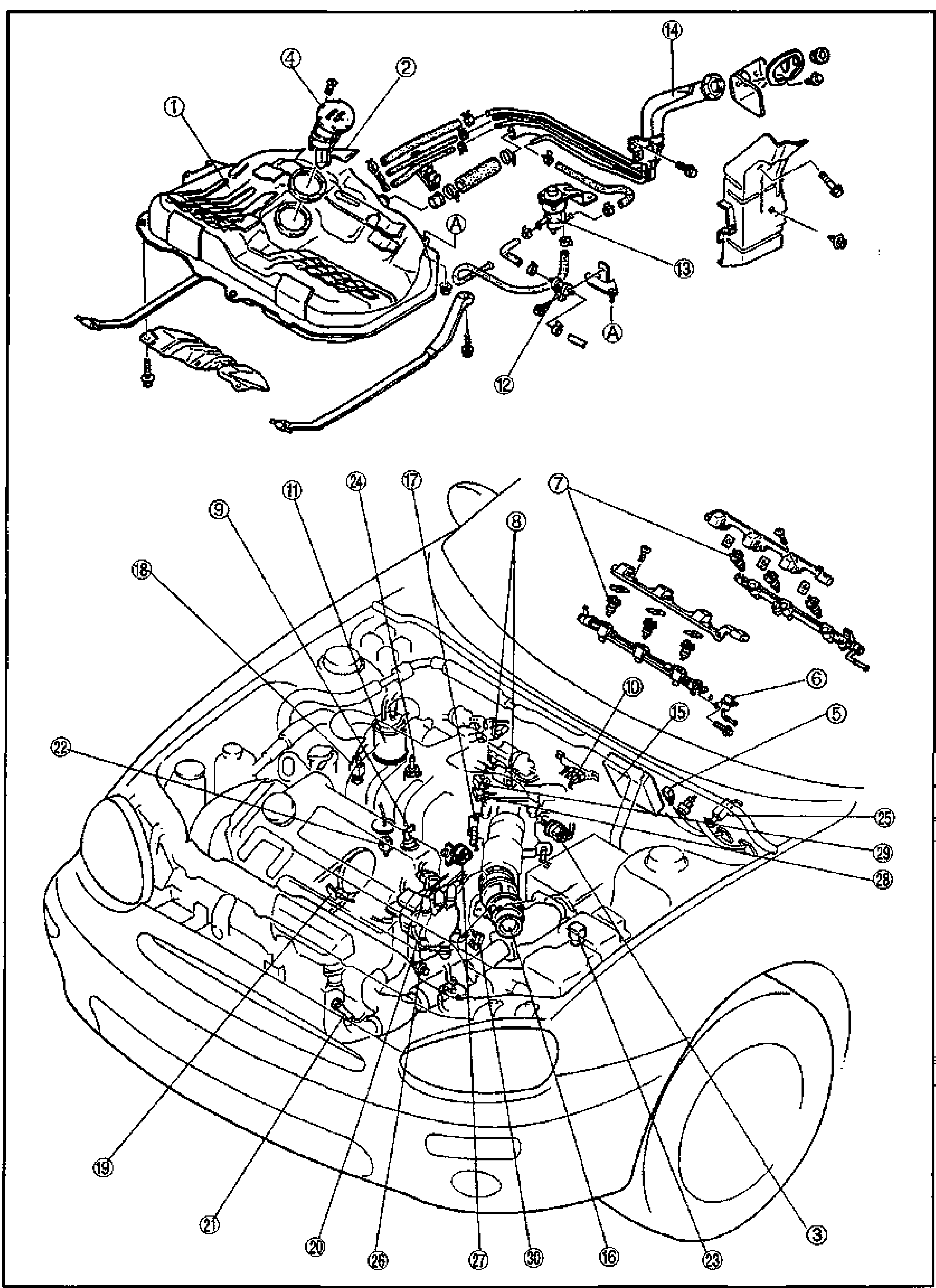
INDEX
F2-4Full-page F2-section index illustration showing fuel and intake/exhaust system components with numbered balloon callouts 1 through 30. Upper portion shows an exploded view of the fuel tank assembly with filler pipe, vapor lines, fuel pump, and a charcoal canister at upper right. Lower portion is a three-quarter front view of the engine compartment of the vehicle with the intake/fuel-injection components called out, including fuel injector rails at right. Letter callout (A) appears as a mating-section reference between the tank lines and the engine bay.
INTAKE-AIR SYSTEM
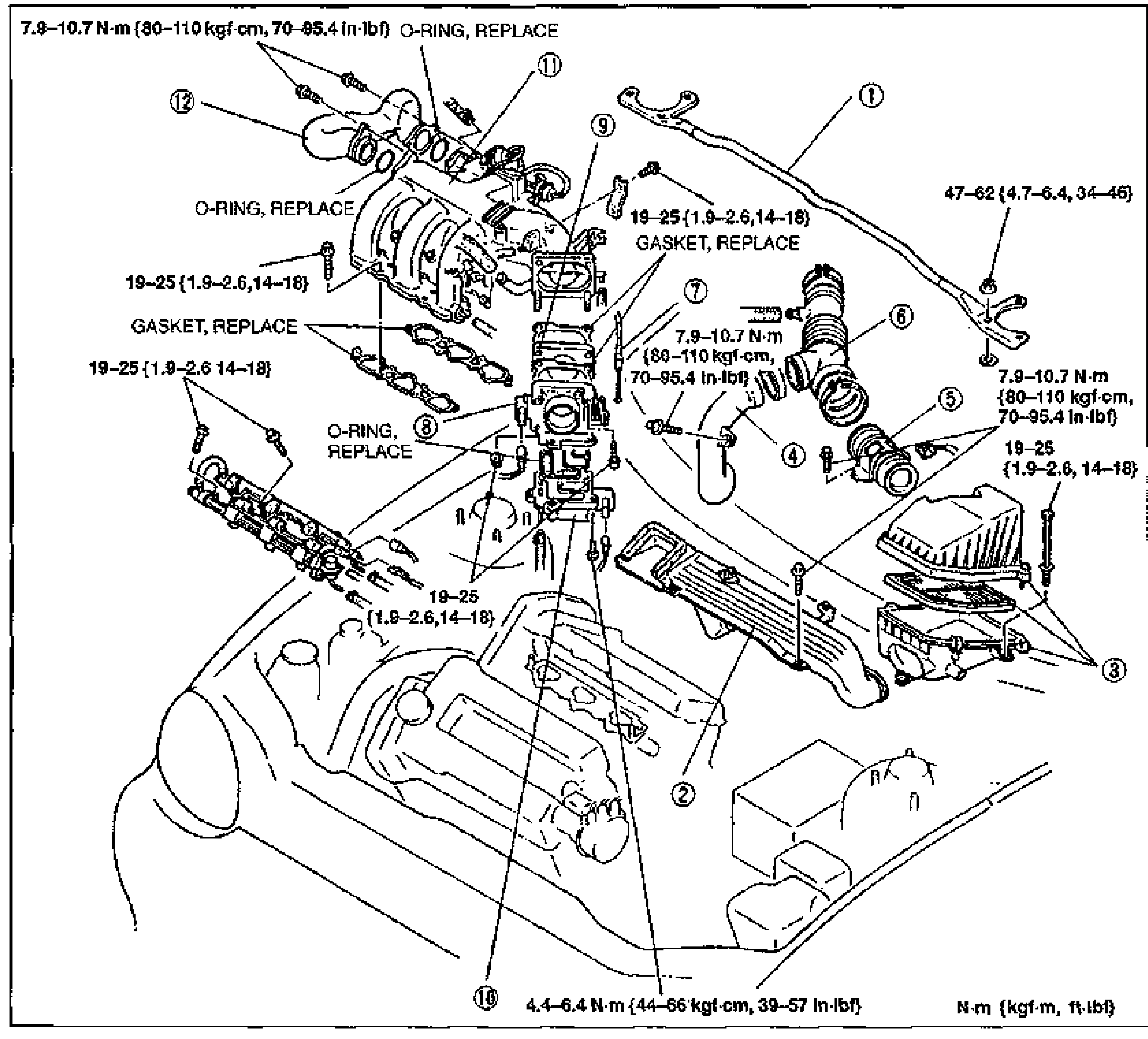
F2-95Exploded view of the intake-air system showing the intake manifold, throttle body, air cleaner assembly, air intake hose, resonance/fresh-air ducts and accelerator cable, installed on the engine. Numbered balloon callouts 1-12 identify each part. Tightening-torque values and O-RING/GASKET REPLACE notes are arrowed to the relevant fasteners and joints.
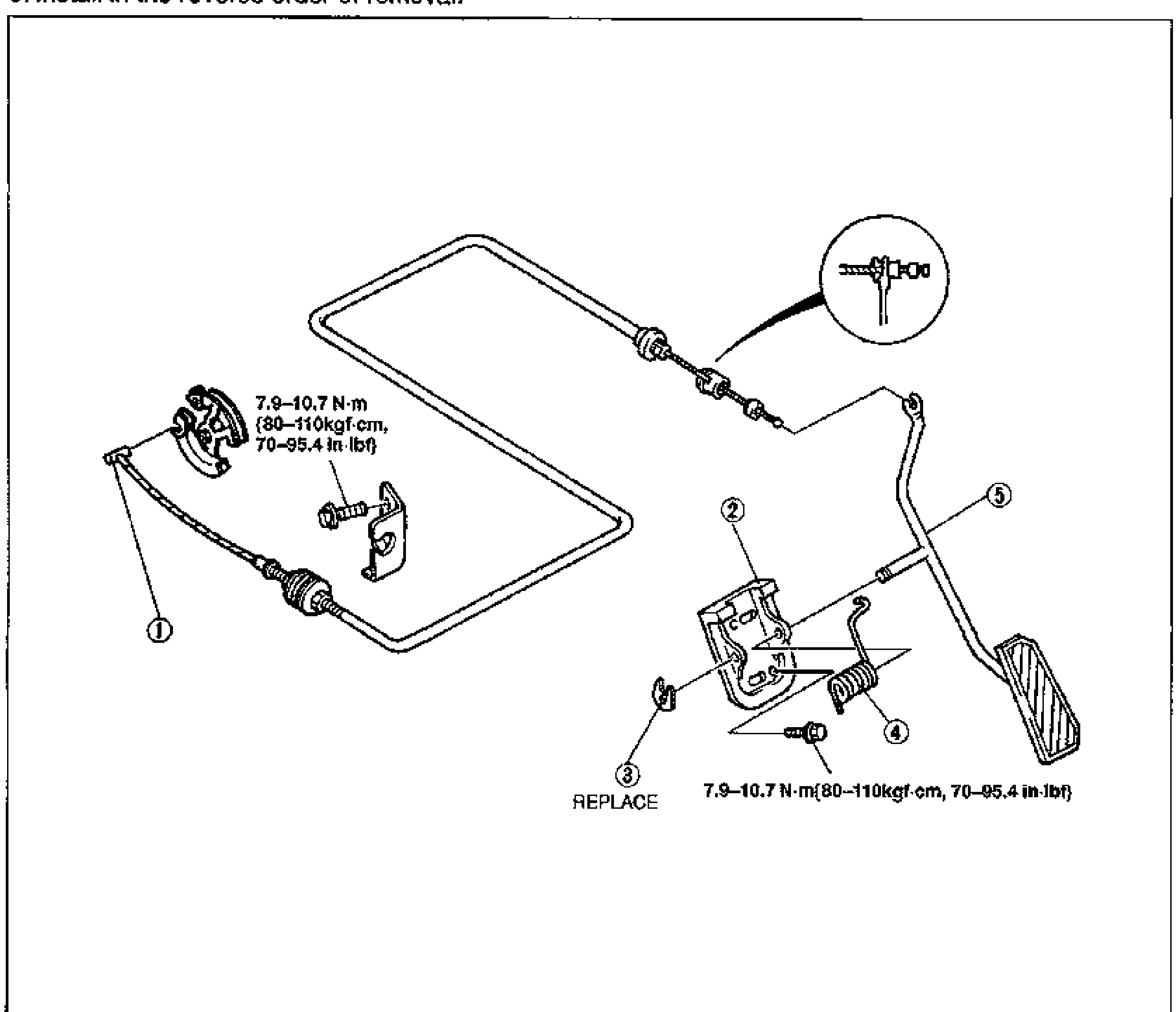
INTAKE-AIR SYSTEM
F2-97Exploded view of the accelerator pedal assembly and accelerator cable. Numbered balloon callouts 1-5 identify the accelerator cable (1), retainer (2), clip (3), return spring (4) and accelerator pedal (5). An inset detail at top-right shows the cable end at the throttle. Tightening-torque notes and a 'REPLACE' note are arrowed to fasteners.
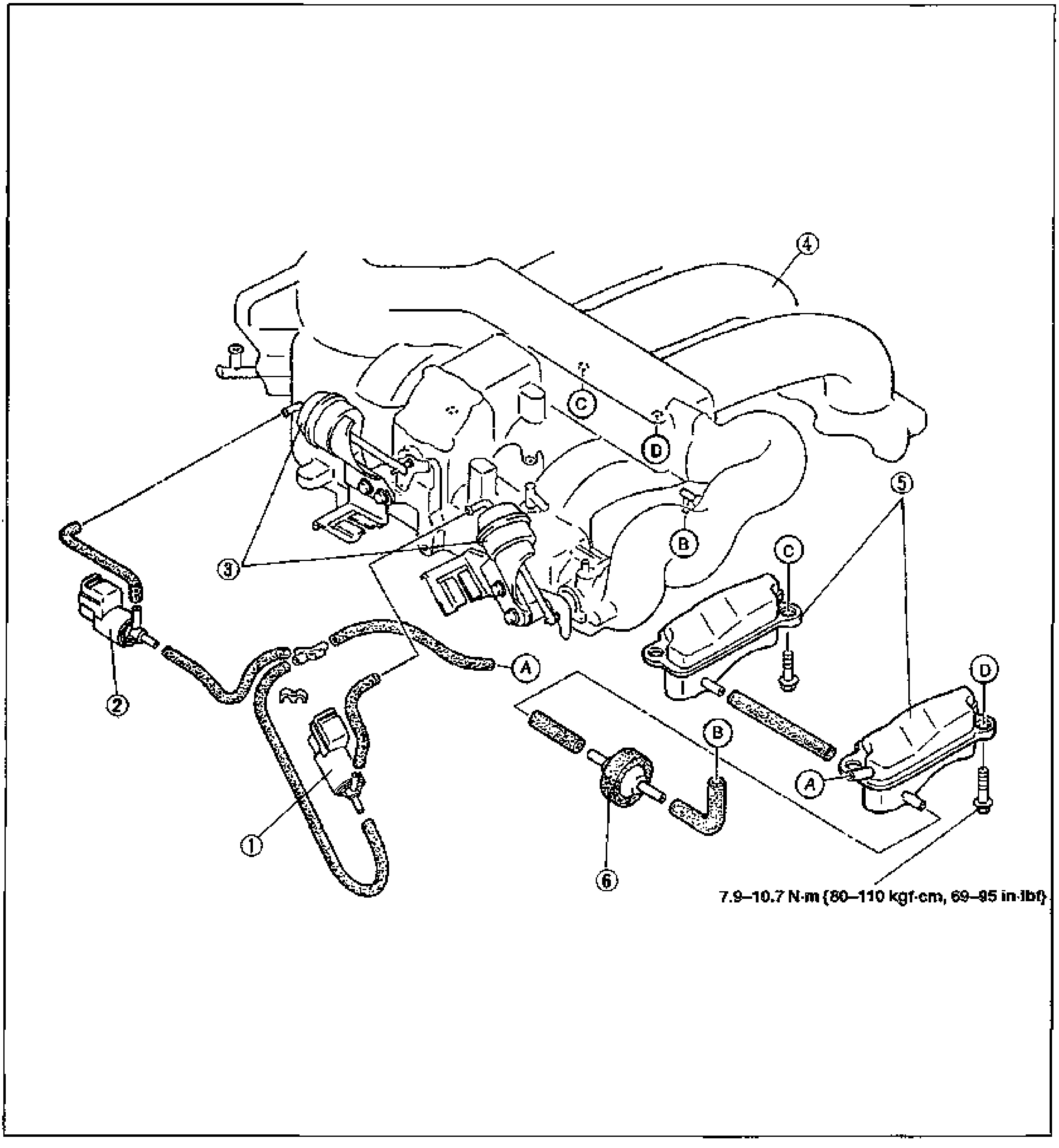
VARIABLE RESONANCE INDUCTION SYSTEM (VRIS)
F2-102Exploded view of the VRIS components on the V6 intake manifold. Numbered balloon callouts 1-6 identify VRIS solenoid valve No.1 (1), VRIS solenoid valve No.2 (2), VRIS shutter valve actuators No.1 and No.2 (3), intake manifold (4), vacuum chamber (5) and check valve (6). Letter callouts A-D mark vacuum hose connection points. Tightening-torque note arrowed to the bolts.
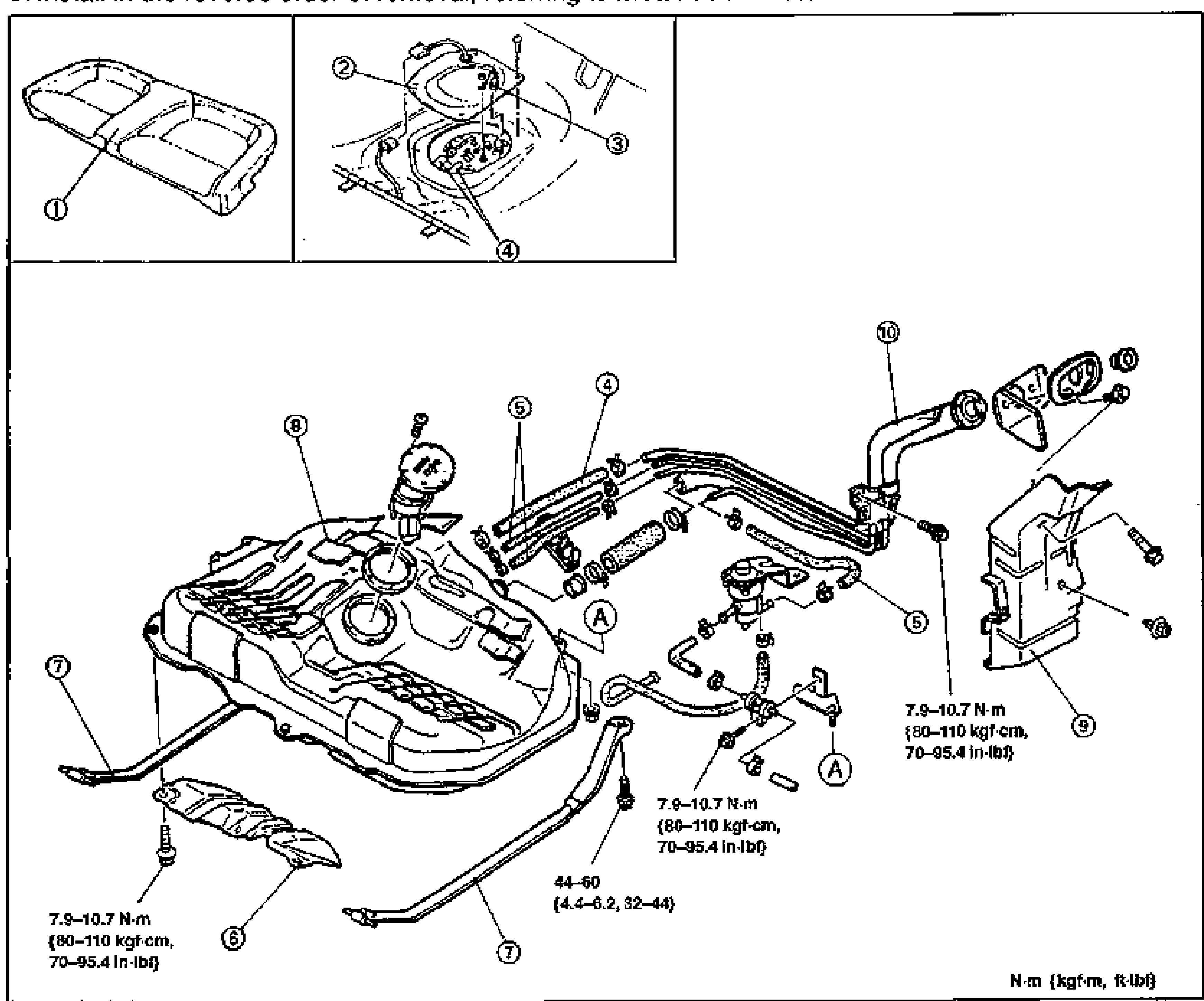
FUEL SYSTEM
F2-108Fuel tank removal exploded view. Top-left inset shows the rear seat cushion (1). Top-center inset shows the fuel pump cover (2), fuel pump connector (3) and a balloon (4) at the pump access opening. Lower main diagram is the full exploded fuel tank assembly with balloons 4-10 plus 5 and A reference markers, showing fuel hose, evaporative hose, insulator, fuel tank strap, fuel tank, protector, separator and filler pipe. Tightening torques are annotated: 7.9-10.7 N·m {80-110 kgf·cm, 70-95.4 in-lbf} at three fastener locations, and 44-60 N·m {4.4-6.2, 32-44} at the strap bolt.
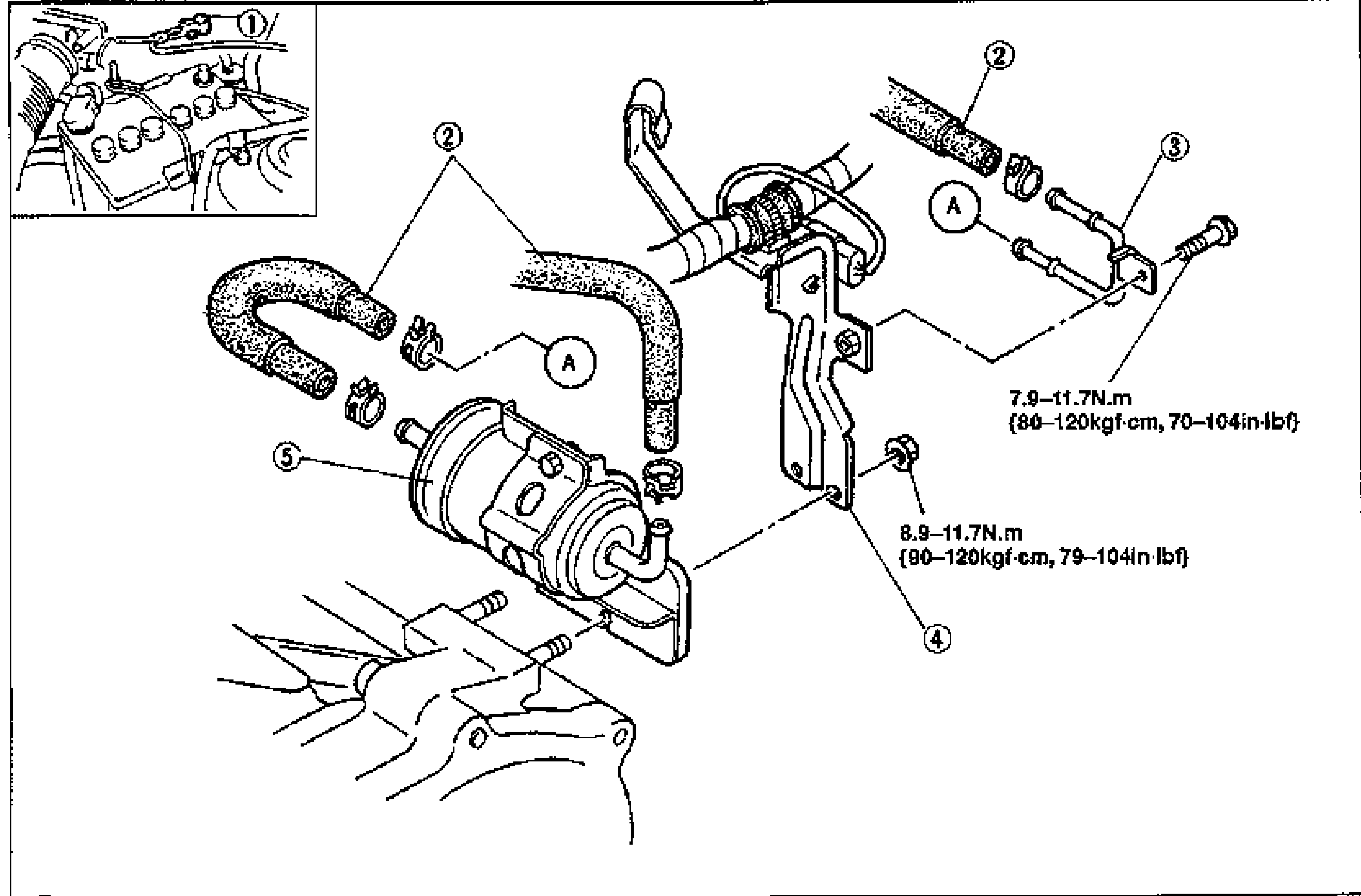
FUEL SYSTEM
F2-109Fuel filter (high pressure side) exploded view. Top-left inset shows the in-bay location with balloon (1) at the negative battery cable. Main diagram shows fuel hoses (2) with clamps, fuel pipe (3), bracket (4), and the fuel filter high-pressure side (5), plus two circled 'A' reference markers. Tightening torques annotated: 7.9-11.7 N·m {80-120 kgf·cm, 70-104 in-lbf} and 8.9-11.7 N·m {90-120 kgf·cm, 79-104 in-lbf}.
FUEL SYSTEM
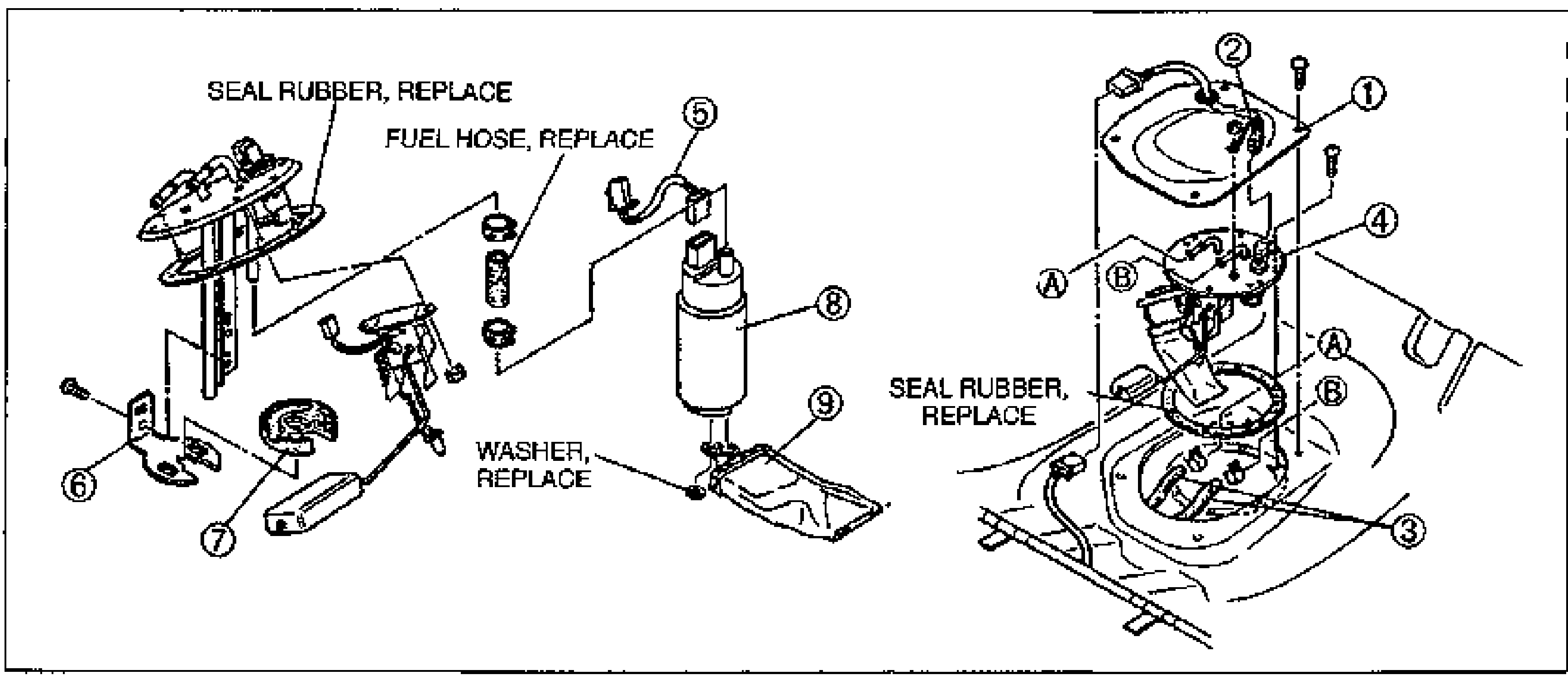
F2-112Fuel pump disassembly exploded view. Left side shows the fuel pump cover assembly with balloons 6 (bracket) and 7 (rubber mount), with callouts SEAL RUBBER, REPLACE and FUEL HOSE, REPLACE. Center shows the fuel pump (8), fuel pump connector (5) and fuel filter low-pressure side (9) with a WASHER, REPLACE callout. Right shows the fuel pump cover (1), fuel gauge sender unit connector (2), fuel hose (3) and fuel gauge (4) with another SEAL RUBBER, REPLACE callout and circled A/B reference markers.
FUEL INJECTOR
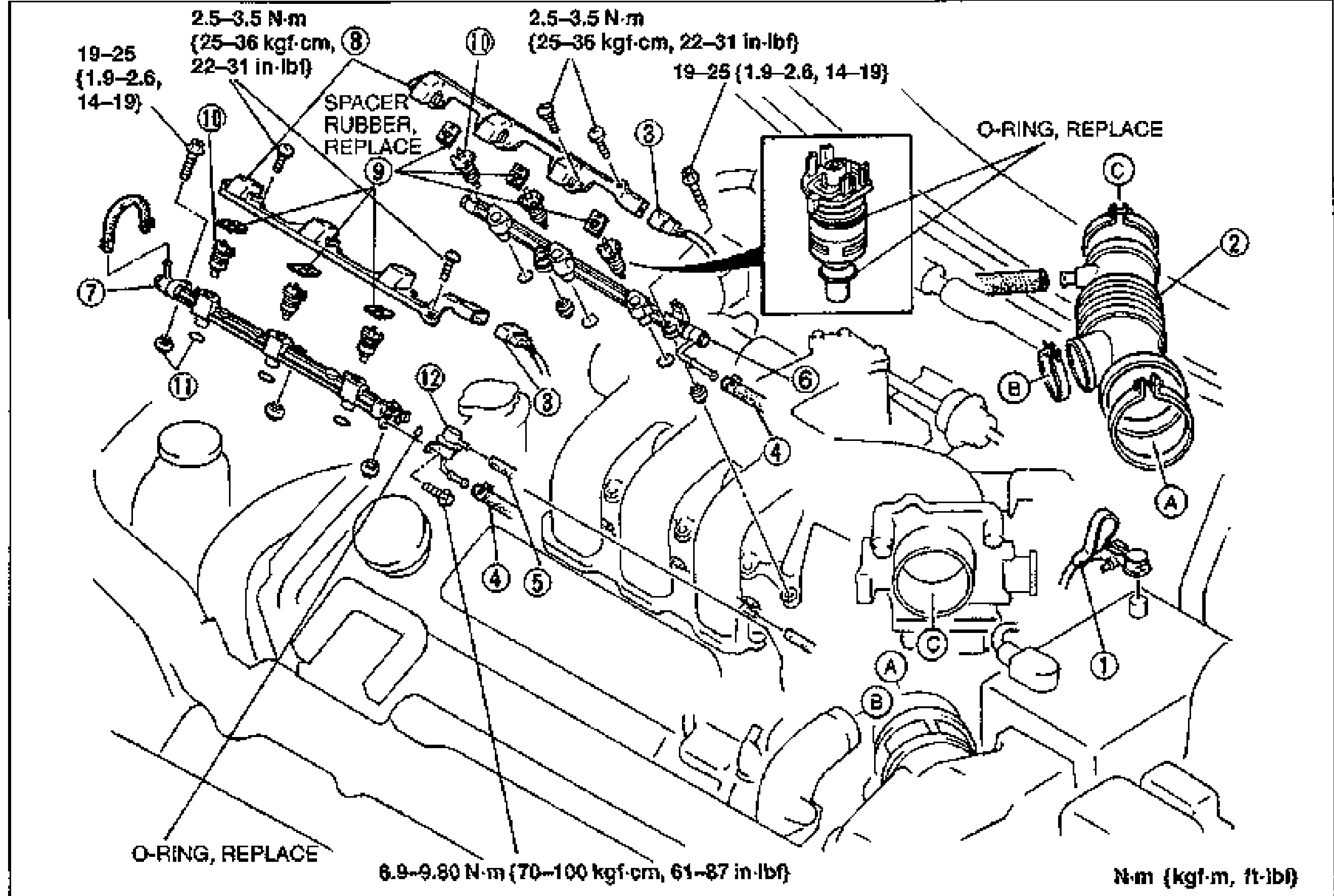
F2-115Large exploded view of the fuel injector / fuel distributor assembly on the V6 engine with numbered balloon callouts 1-12 and lettered fastener callouts A, B, C. Tightening torque values are labeled near the bolts. Notes indicate O-RING REPLACE and SPACER RUBBER REPLACE. An inset shows a single fuel injector with O-ring.
EXHAUST SYSTEM
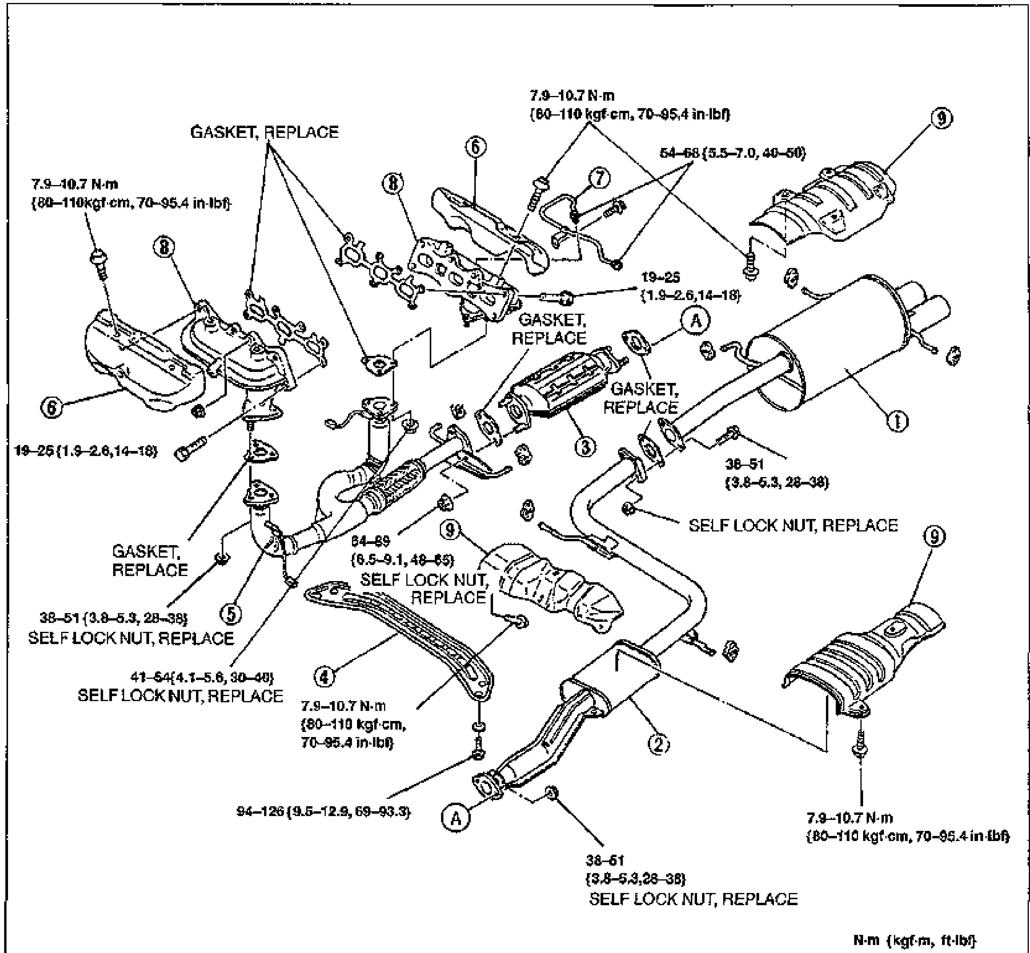
F2-121Large exploded view of the complete exhaust system with numbered balloon callouts 1-9 and lettered fastener callouts (A). Shows the exhaust manifolds, EGR pipe, three way catalytic converter, front pipe, presilencer, main silencer, transverse member and insulators. Tightening torque values and GASKET REPLACE / SELF LOCK NUT REPLACE notes are labeled throughout.
EXHAUST SYSTEM - CALIFORNIA
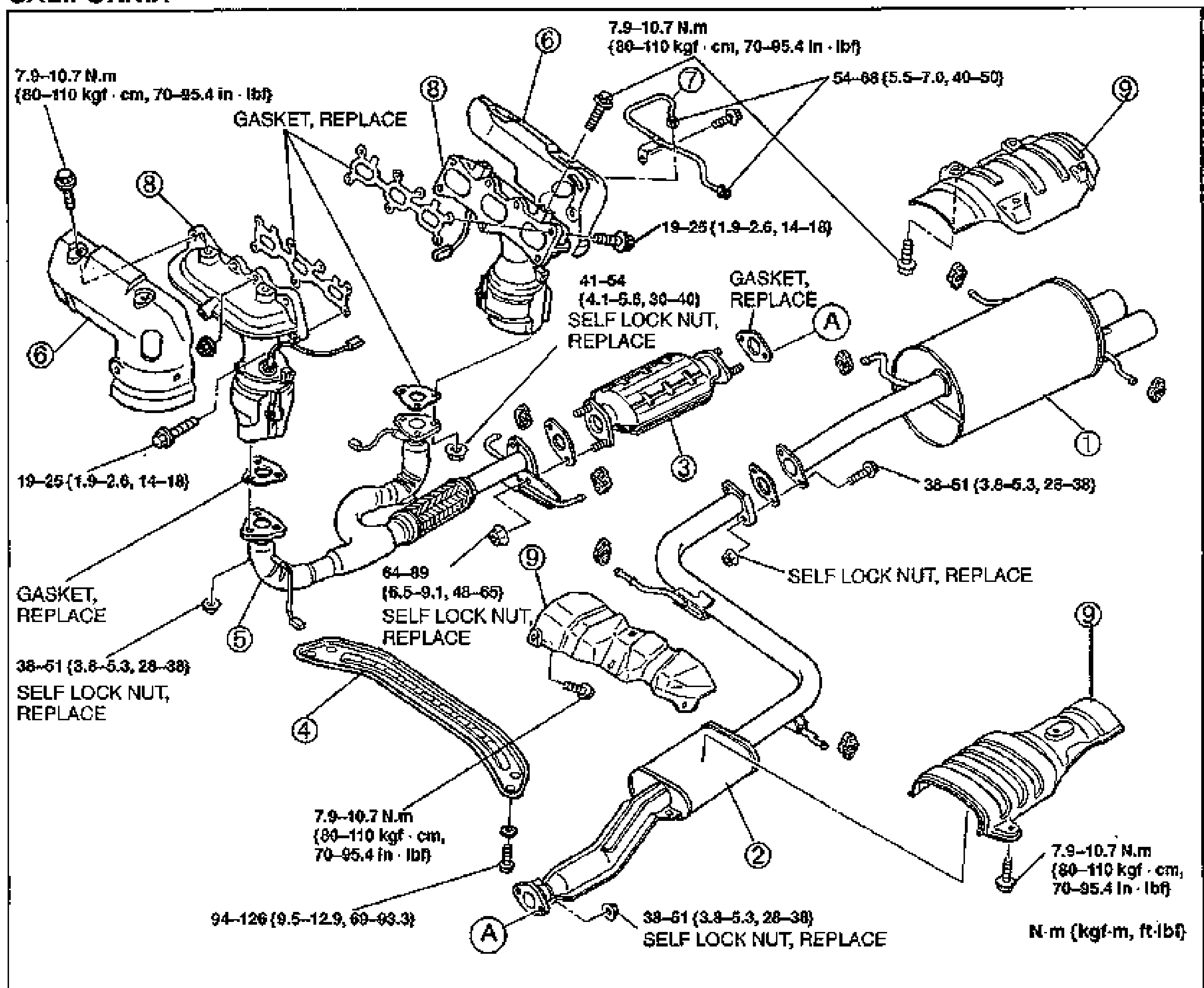
F2-122Large exploded view of the California-specification exhaust system with numbered balloon callouts 1-9 and lettered fastener callouts (A). Shows the exhaust manifolds, EGR pipe, three way catalytic converter, warm up three way catalytic converter, front pipe, presilencer, main silencer, transverse member and insulators. Tightening torque values and GASKET REPLACE / SELF LOCK NUT REPLACE notes are labeled throughout.
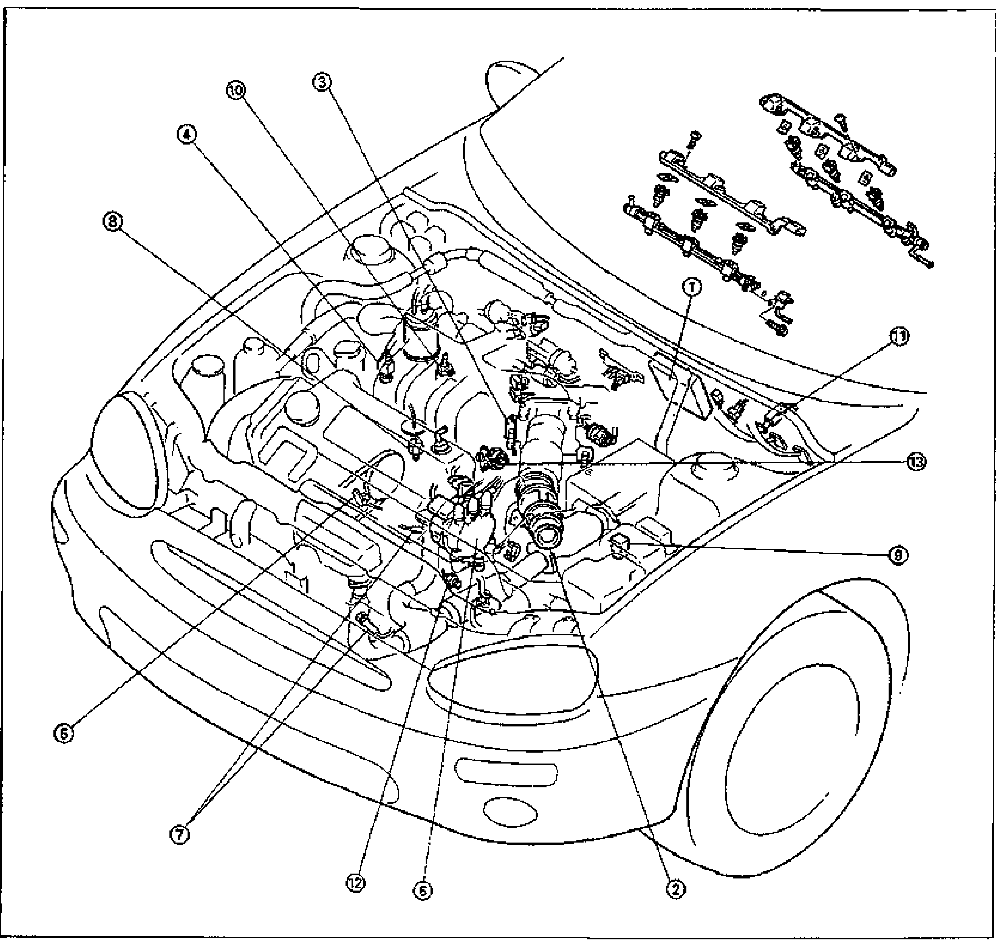
CONTROL SYSTEM
F2-140Cutaway line drawing of the front of the MX-3 with the engine bay exposed and numbered balloon callouts (1-13) pointing to control-system components: 1 ECM, 2 volume air flow sensor, 3 throttle position sensor, 4 engine coolant temperature sensor, 5 crankshaft position sensor, 6 camshaft position sensor, 7 heated oxygen sensor, 8 knock sensor, 9 main relay, 10 P/S pressure switch, 11 clutch switch, 12 neutral switch, 13 EGR valve position sensor. An inset at the top right shows the fuel injector rail / harness assembly.
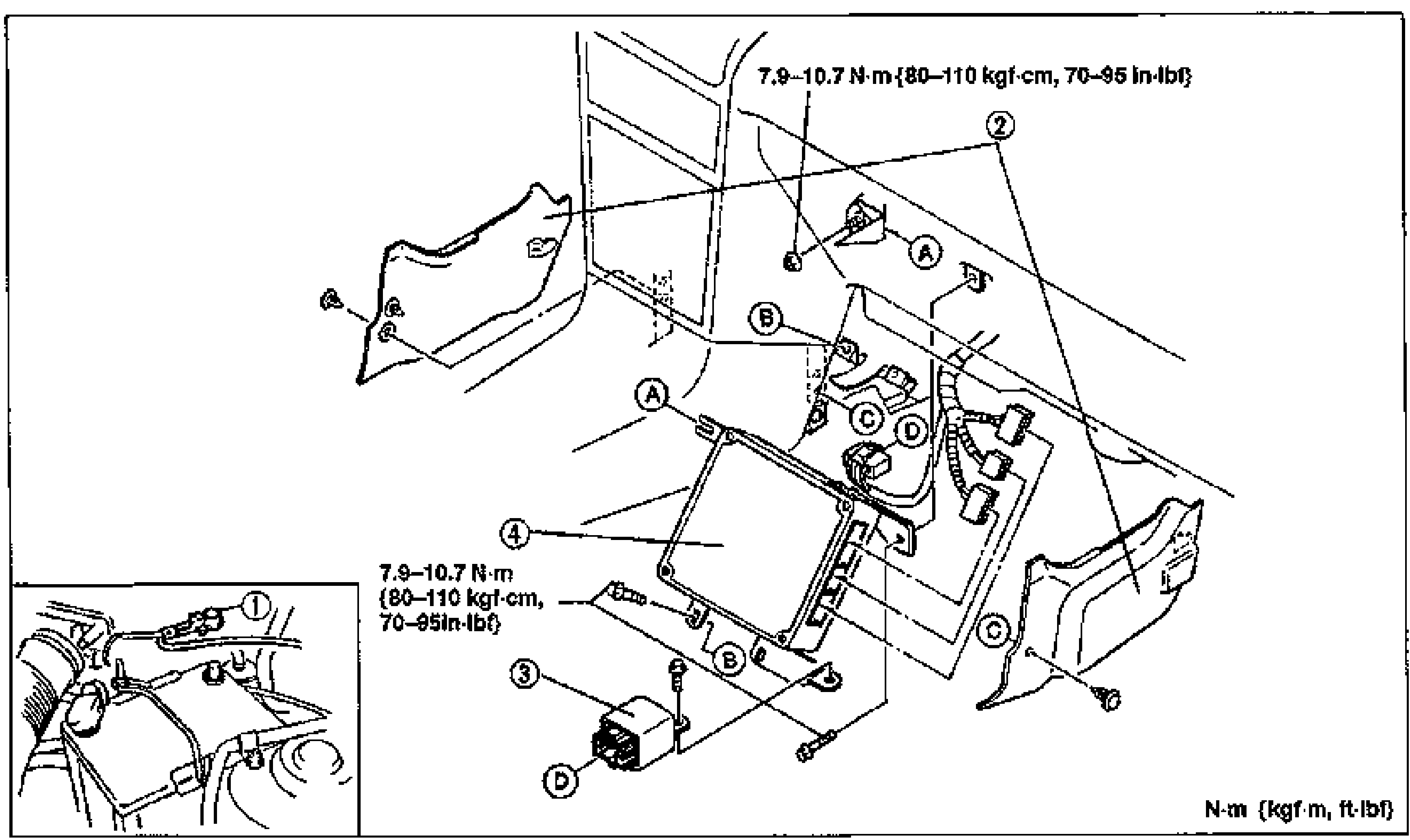
ENGINE CONTROL MODULE (ECM)
F2-141Exploded view of the ECM mounting behind the side wall trim. Numbered balloon callouts: 1 negative battery cable (shown in a separate inset at lower-left), 2 side wall trim panel, 3 fuel pump relay, 4 ECM. Lettered bolt callouts A, B, C, D mark fasteners. Torque callouts read 7.9-10.7 N·m {80-110 kgf·cm, 70-95 in-lbf} (shown twice). A unit legend in the bottom-right corner reads N·m {kgf·m, ft-lbf}.
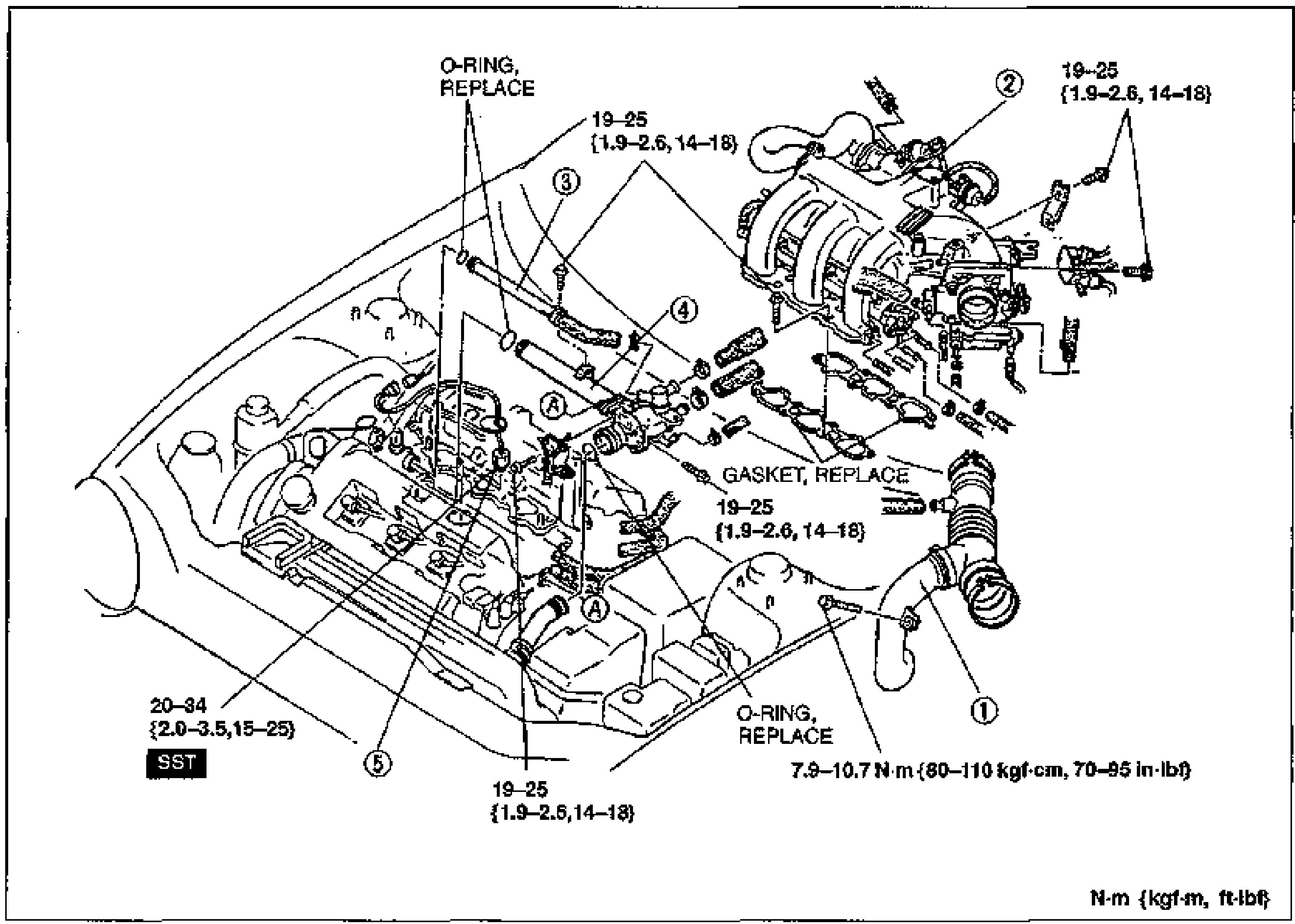
KNOCK SENSOR
F2-156Exploded view of the intake manifold area for knock sensor removal/installation. Numbered balloons 1-5 identify components: 1 air hose, 2 intake manifold, 3 bypass pipe, 4 water pipe, 5 knock sensor. Tightening-torque callouts shown at several bolt locations; O-rings and gasket marked REPLACE. Bolts labeled A. The knock sensor (5) is marked with an SST callout.
Engine Electrical System
G25 diagrams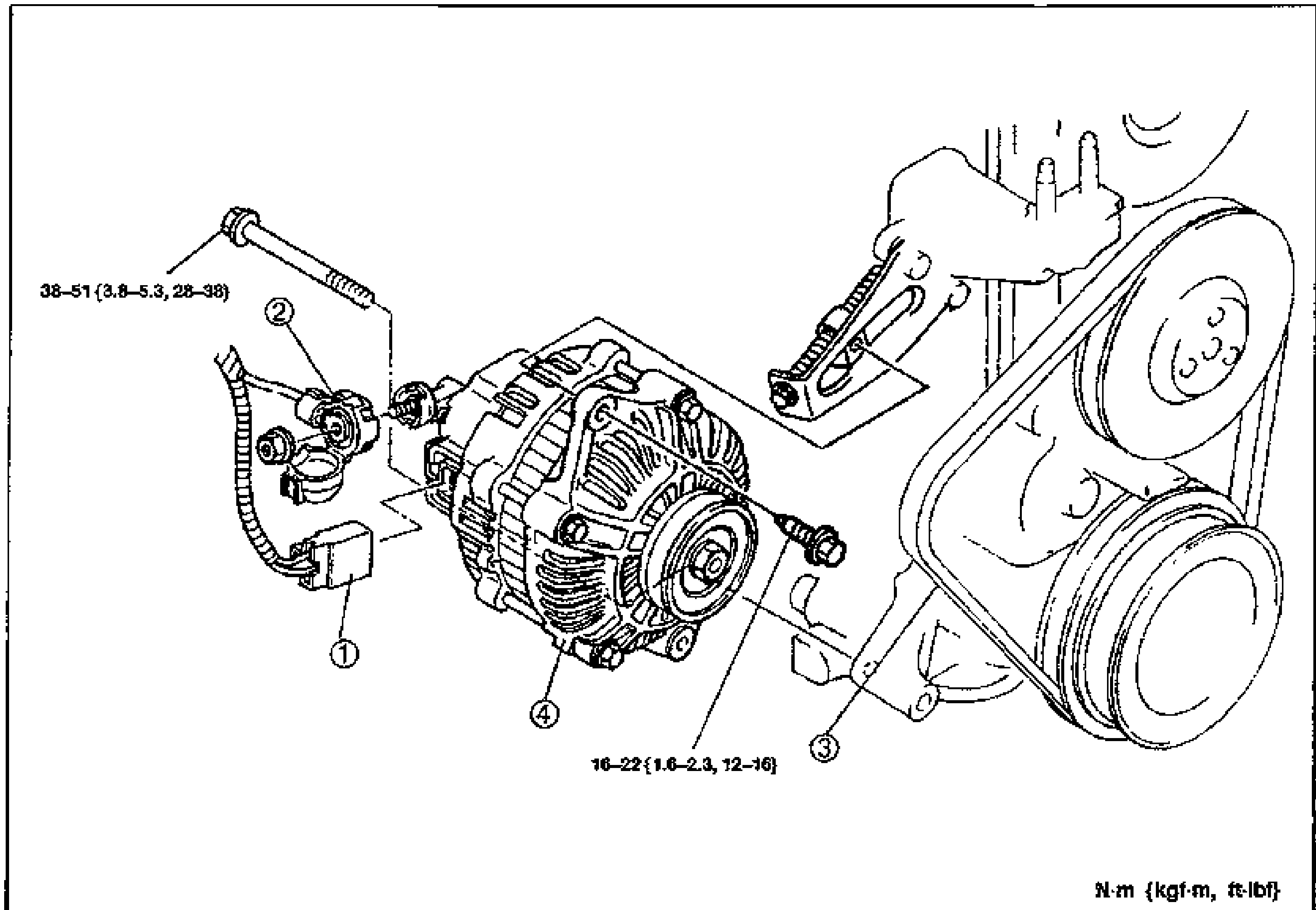
CHARGING SYSTEM - GENERATOR Removal / Installation (B6 DOHC)
G-12Exploded view of the B6 DOHC generator (alternator) removal/installation. Shows the connector and generator terminal B wire on the left, the alternator with mounting bolts, the adjustment bracket, and the drive belt/pulleys on the right. Numbered balloon callouts 1-4 with tightening torques: 38-51 N·m {3.8-5.3 kgf·m, 28-38 ft·lbf} for the upper through bolt and 16-22 N·m {1.6-2.3 kgf·m, 12-16 ft·lbf} for the lower bolt. Units note: N·m {kgf·m, ft·lbf}.
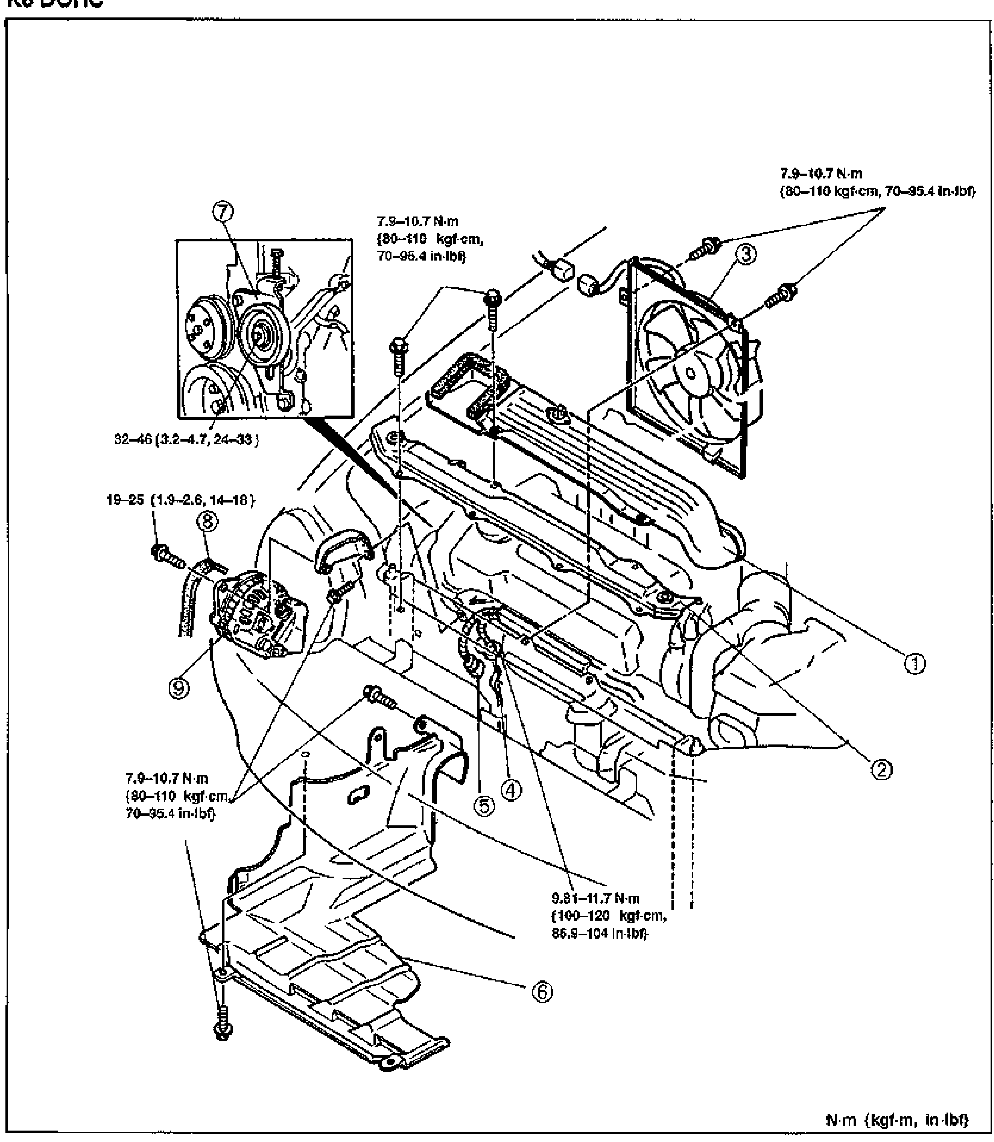
CHARGING SYSTEM - GENERATOR Removal / Installation (K8 DOHC)
G-13Large exploded view of the K8 DOHC (V6) generator removal/installation. Shows the fresh-air duct, radiator upper bracket, condenser fan, generator terminal B wire, connector, splash shield, belt tensioner (inset detail at upper left), drive belt, and the generator mounted to the engine. Numbered balloon callouts 1-9 with tightening-torque annotations. Units note: N·m {kgf·m, in·lbf}.
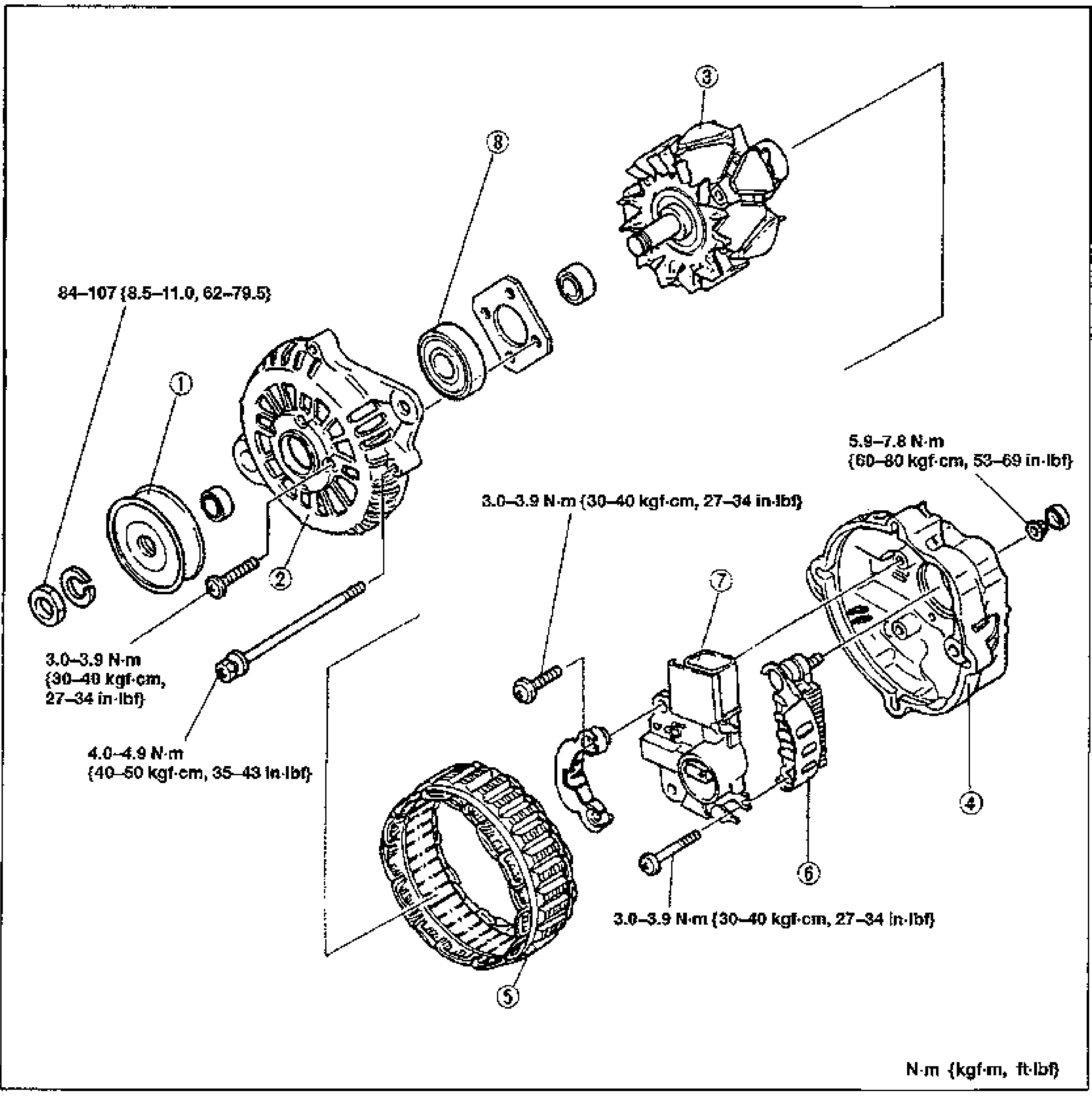
CHARGING SYSTEM — Disassembly / Assembly (Alternator, B6 DOHC)
G-14Exploded view of the B6 DOHC alternator showing assembly order with numbered balloon callouts and tightening torques. Components from left: pulley (1), front bracket (2), rotor (3), rear bracket (4), stator (5), rectifier (6), brush holder assembly (7), and bearing (8). Tightening torques annotated at fastener locations.
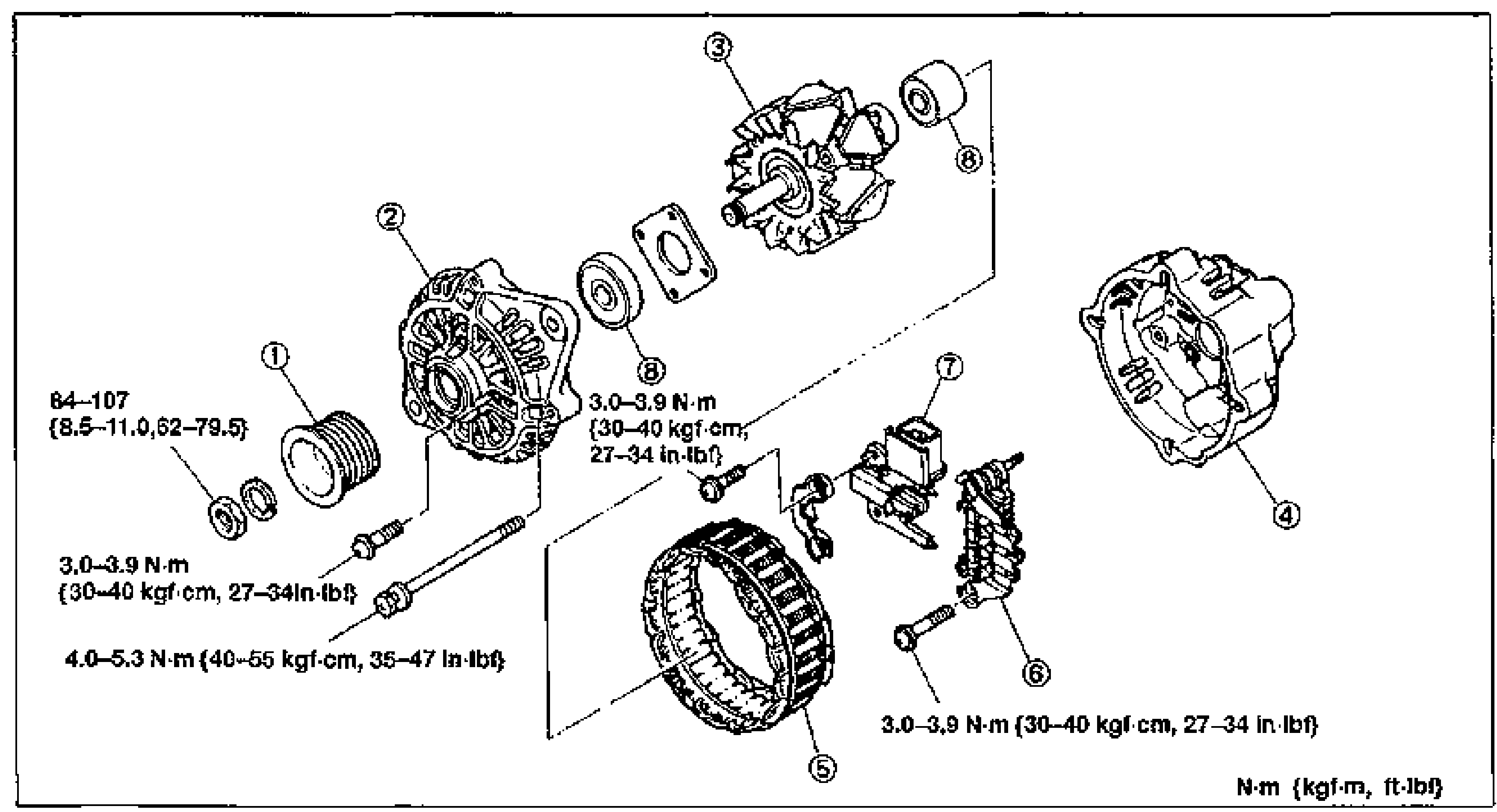
CHARGING SYSTEM — Alternator Disassembly / Assembly (K8 DOHC)
G-15Exploded view of the K8 DOHC alternator with numbered balloon callouts (1-8) and tightening torques. Components: pulley (1), front bracket (2), rotor (3), rear bracket (4), stator (5), rectifier (6), brush holder assembly (7), bearing (8).
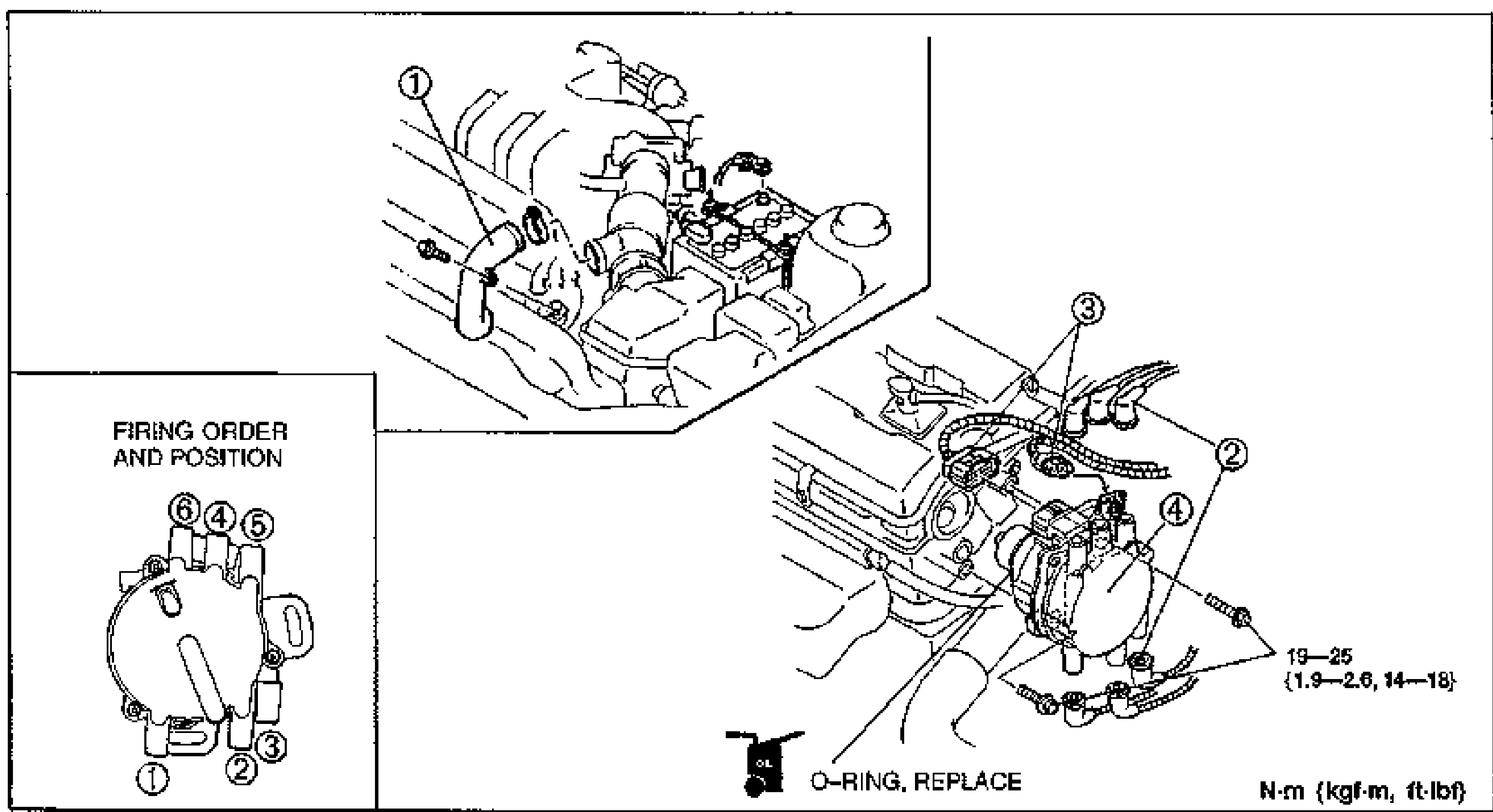
IGNITION SYSTEM
G-29K8 DOHC distributor removal/installation exploded view in the engine bay. Numbered callouts: 1 resonance duct (K8), 2 high-tension lead, 3 connector, 4 distributor. An O-RING REPLACE note marks the distributor O-ring. Tightening torque 19—25 {1.9—2.6, 14—18} N·m {kgf·m, ft·lbf} for the distributor mounting bolt. An inset (lower left) shows FIRING ORDER AND POSITION on the distributor cap: terminals 6,4,5 top and 1,2,3 bottom.
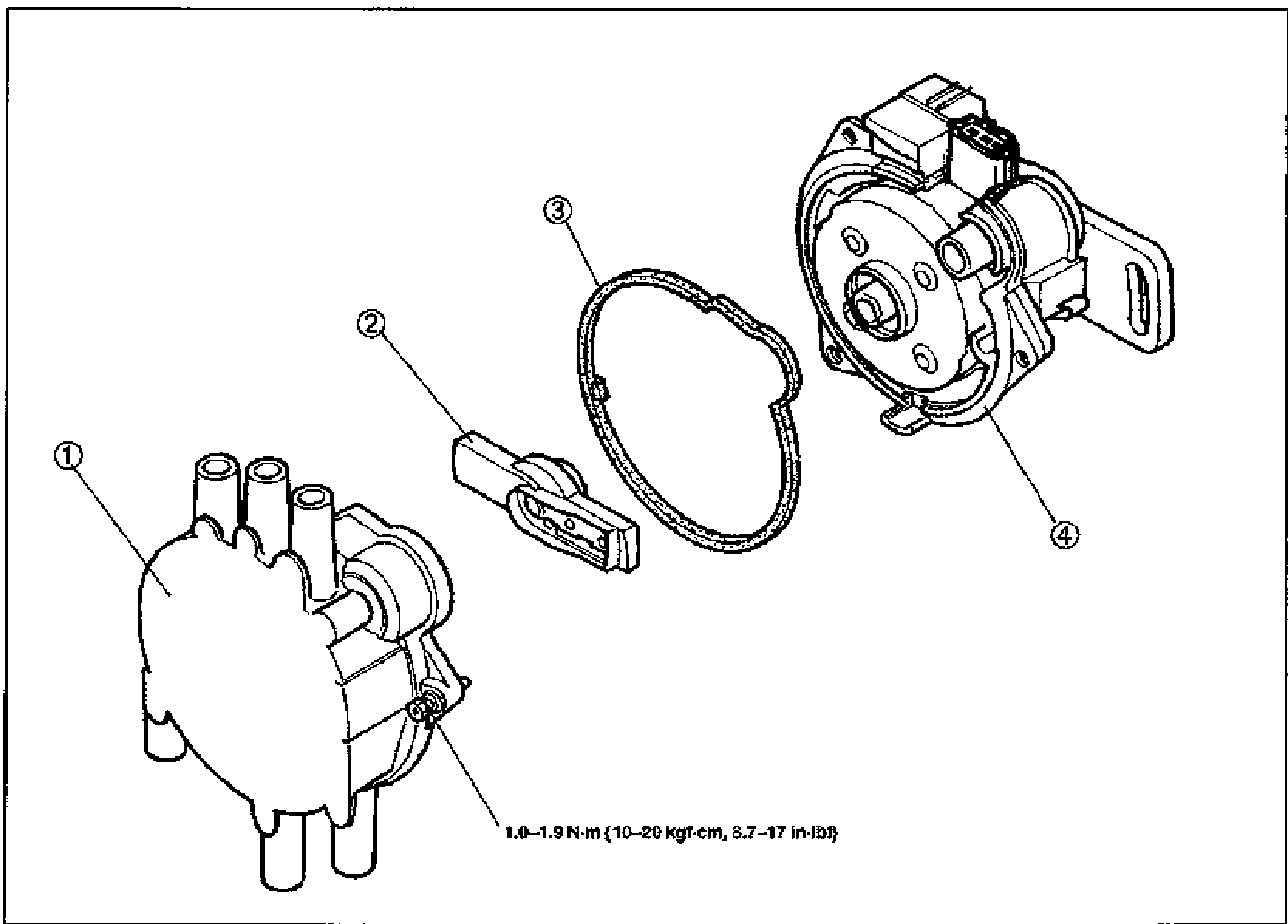
IGNITION SYSTEM
G-30K8 DOHC distributor exploded view. Numbered callouts: 1 cap (with high-tension lead towers), 2 rotor, 3 packing (gasket ring), 4 distributor body with connector and mounting bracket. Tightening torque note for the cap screws: 1.0—1.9 N·m {10—20 kgf·cm, 8.7—17 in·lbf}.
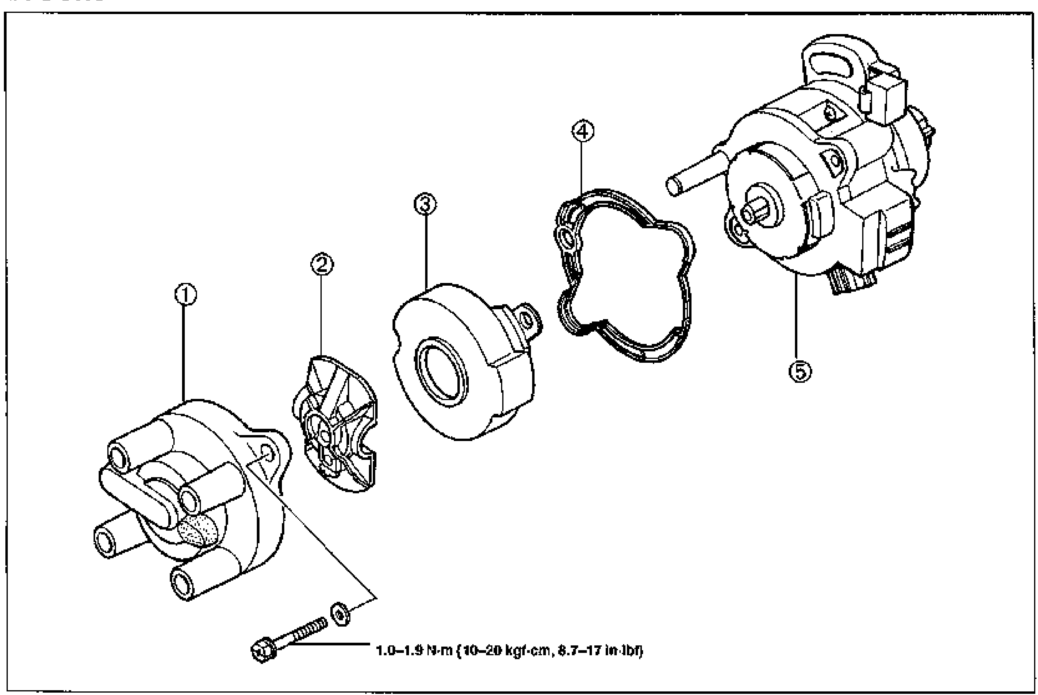
IGNITION SYSTEM
G-31B6 DOHC distributor exploded view. Numbered callouts: 1 cap (with high-tension lead towers and a retaining screw with washer), 2 rotor, 3 cover, 4 packing (gasket ring), 5 distributor body with shaft and connector. Tightening torque note for the cap screw: 1.0—1.9 N·m {10—20 kgf·cm, 8.7—17 in·lbf}.
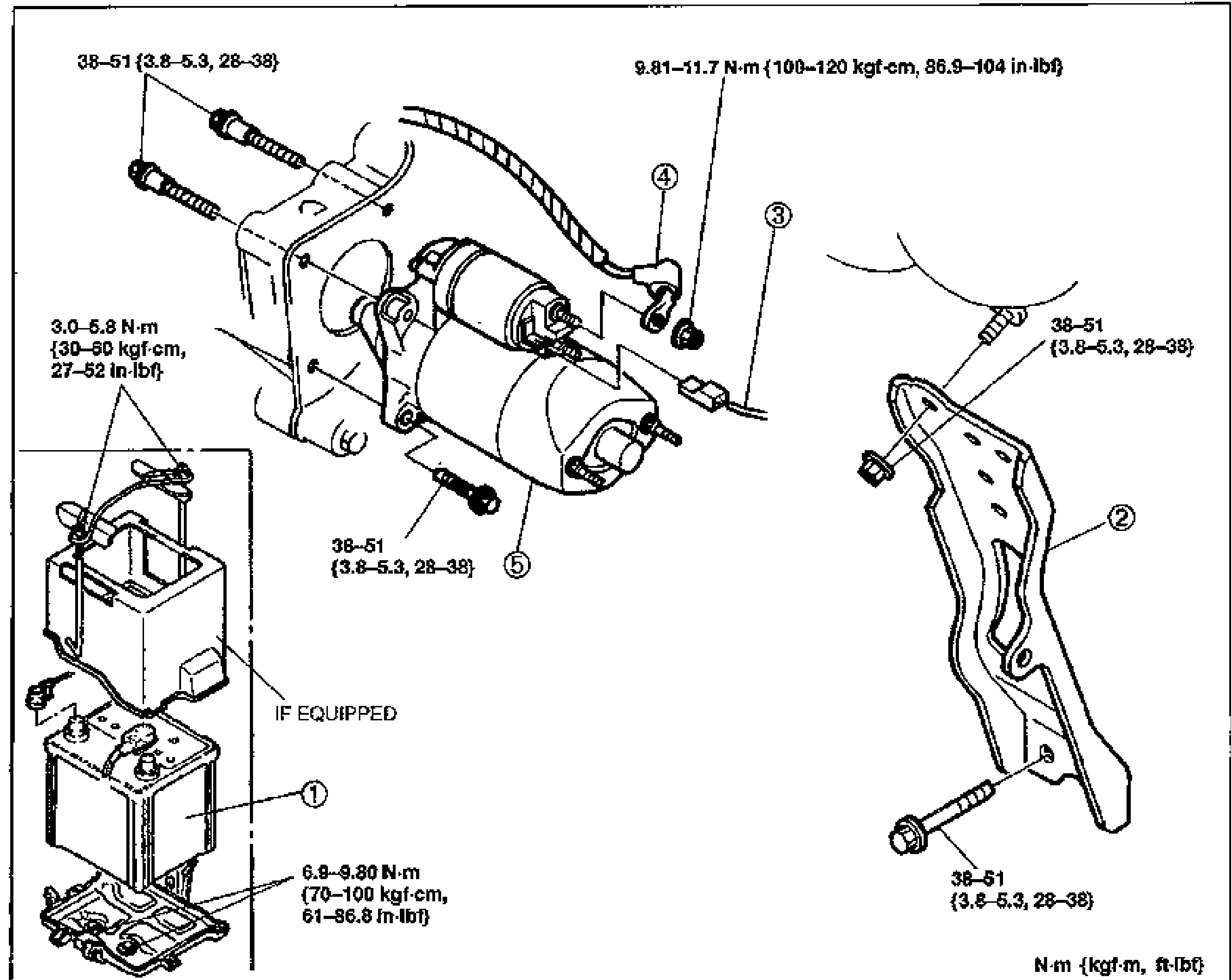
STARTING SYSTEM — STARTER
G-34Exploded view of the B6 DOHC starter mounting. Shows the battery (1) and battery tray, intake manifold bracket (2), terminal S wire (3), terminal B wire (4), and the starter (5). Tightening torques are called out at each fastener: 38-51 N·m {3.8-5.3 m-kg, 28-38 ft-lbf} for the starter/bracket bolts; 9.81-11.7 N·m {100-120 kgf-cm, 86.9-104 in-lbf} for terminal B; 3.0-5.8 N·m {30-60 kgf-cm, 27-52 in-lbf} for the small battery hold-down screws (if equipped); 6.9-9.80 N·m {70-100 kgf-cm, 61-86.8 in-lbf} for the battery base. Torque-unit legend N·m {kgf·m, ft-lbf}.
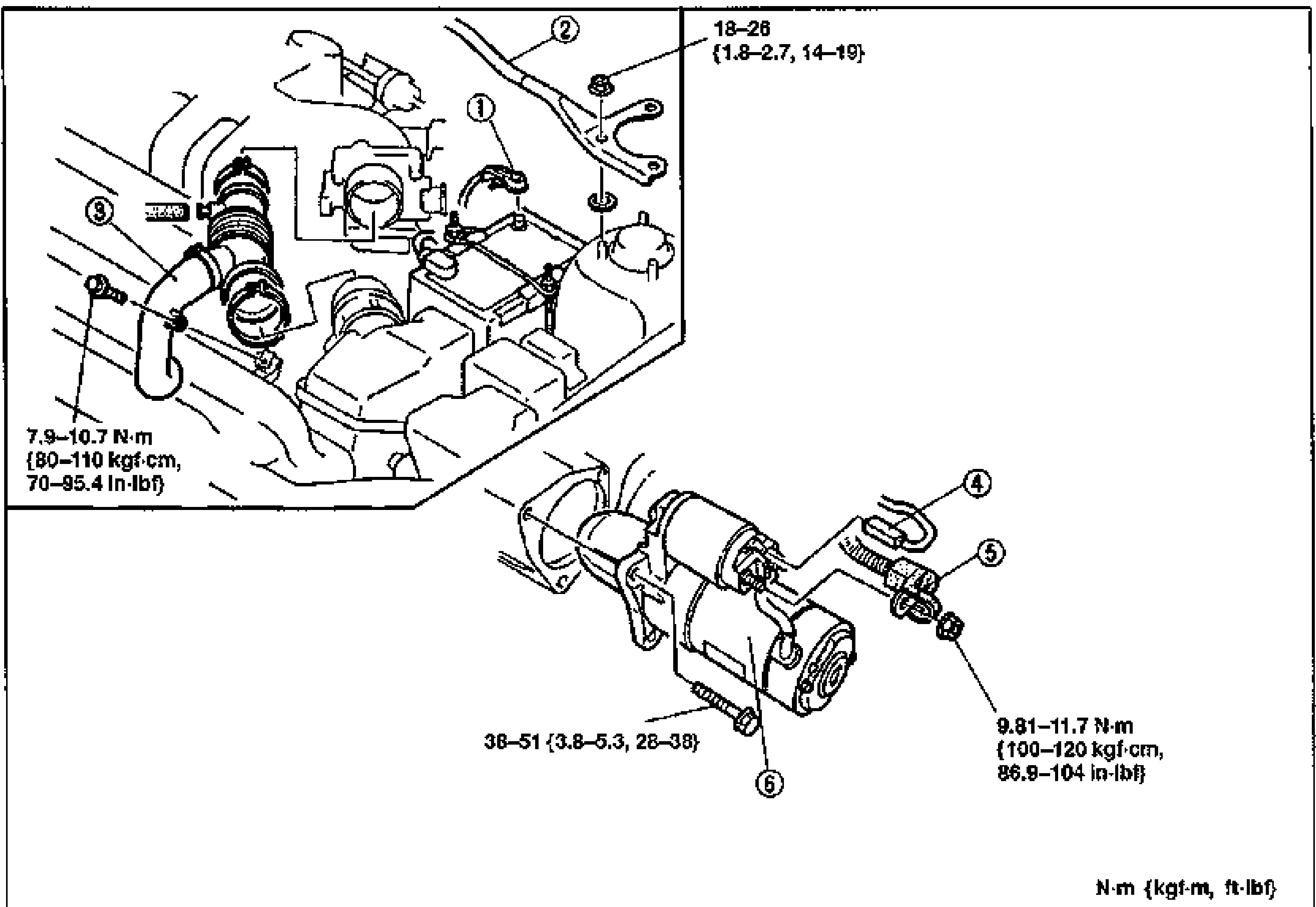
STARTING SYSTEM — STARTER Removal / Installation (K8 DOHC MTX)
G-35Exploded view of the K8 DOHC (MTX) starter mounting in the engine bay. Callouts: negative battery cable (1), strut bar (2), intake air hose (3), terminal S wire (4), terminal B wire (5), and starter (6). Tightening torques: strut bar 18-26 N·m {1.8-2.7 m-kg, 14-19 ft-lbf}; intake air hose clamp 7.9-10.7 N·m {80-110 kgf-cm, 70-95.4 in-lbf}; starter bolts 38-51 N·m {3.8-5.3 m-kg, 28-38 ft-lbf}; terminal B nut 9.81-11.7 N·m {100-120 kgf-cm, 86.9-104 in-lbf}. Torque-unit legend N·m {kgf·m, ft-lbf}.
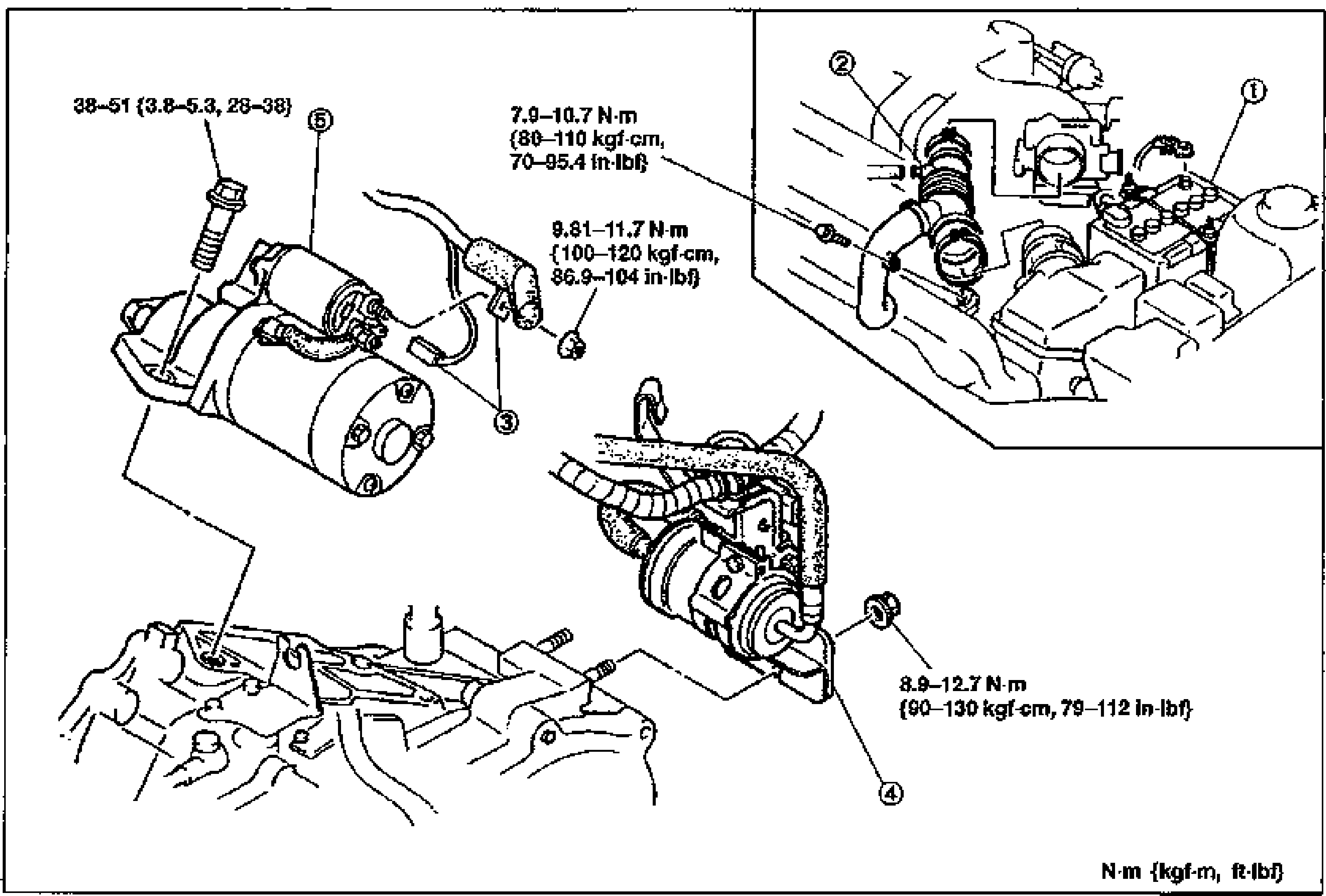
STARTING SYSTEM — STARTER Removal / Installation (ATX) and Performance Inspection
G-36Exploded view of the ATX starter mounting in the engine bay. Callouts: negative battery cable (1), intake air hose (2), terminal S and B wire (3), fuel filter high-pressure side (4), and starter (5). Tightening torques: starter bolts 38-51 N·m {3.8-5.3 m-kg, 28-38 ft-lbf}; intake air hose clamp 7.9-10.7 N·m {80-110 kgf-cm, 70-95.4 in-lbf}; terminal B nut 9.81-11.7 N·m {100-120 kgf-cm, 86.9-104 in-lbf}; fuel filter 8.9-12.7 N·m {90-130 kgf-cm, 79-112 in-lbf}. Torque-unit legend N·m {kgf·m, ft-lbf}.
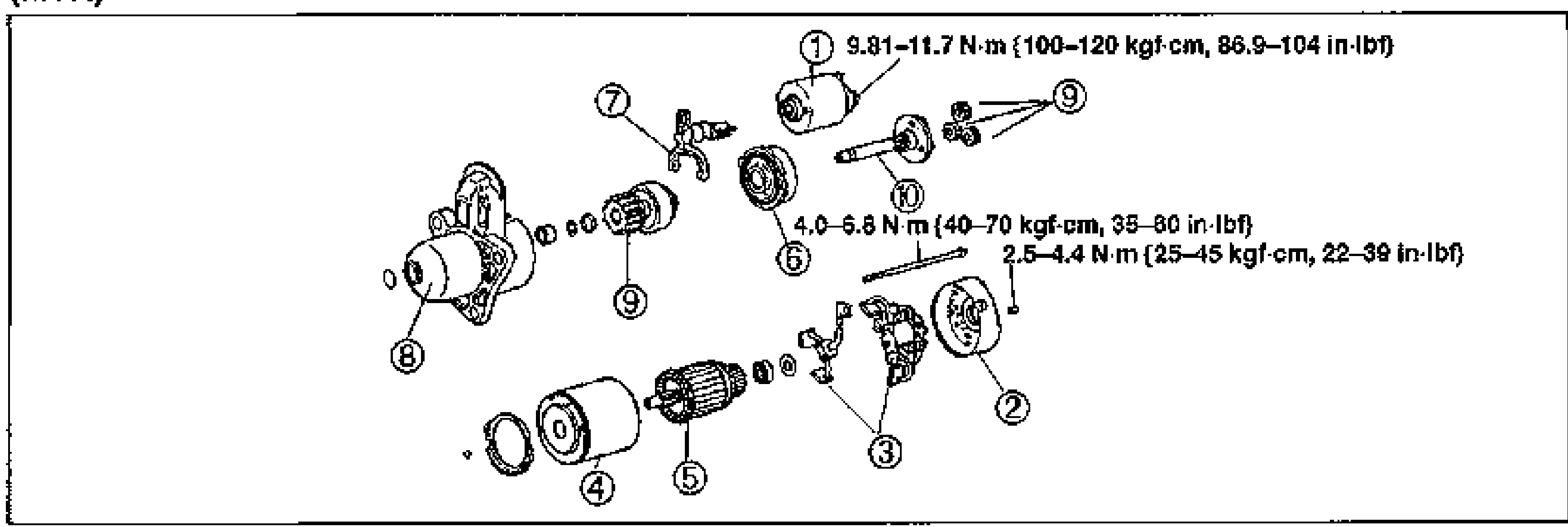
STARTING SYSTEM — STARTER Adjustment of pinion gap, No load test, Disassembly / Assembly
G-37Exploded view of the K8 DOHC (MTX) starter disassembly. Callouts: magnetic switch (1), rear bracket (2), brush holder assembly (3), yoke (4), armature (5), internal gear (6), lever (7), front bracket (8), pinion gear and planetary gears (9), shaft (10). Torques: magnetic switch terminal 9.81-11.7 N·m {100-120 kgf-cm, 86.9-104 in-lbf}; 4.0-6.8 N·m {40-70 kgf-cm, 35-60 in-lbf}; 2.5-4.4 N·m {25-45 kgf-cm, 22-39 in-lbf}.
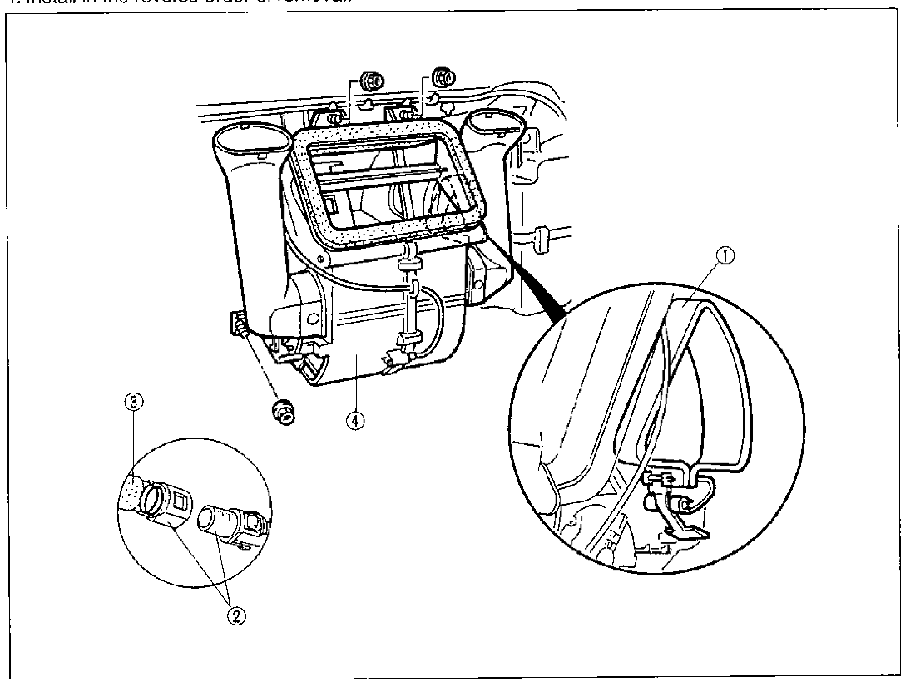
HEATER UNIT - Removal / Installation
G-37Exploded/structural view of the heater unit installed behind the dash with detail circle insets. Numbered balloon callouts: 1 = Seal plate, 2 = Hose connector (detail circle, lower left), 3 = Heater hose, 4 = Heater unit. Detail circle at right shows the heater unit mounting at the firewall.
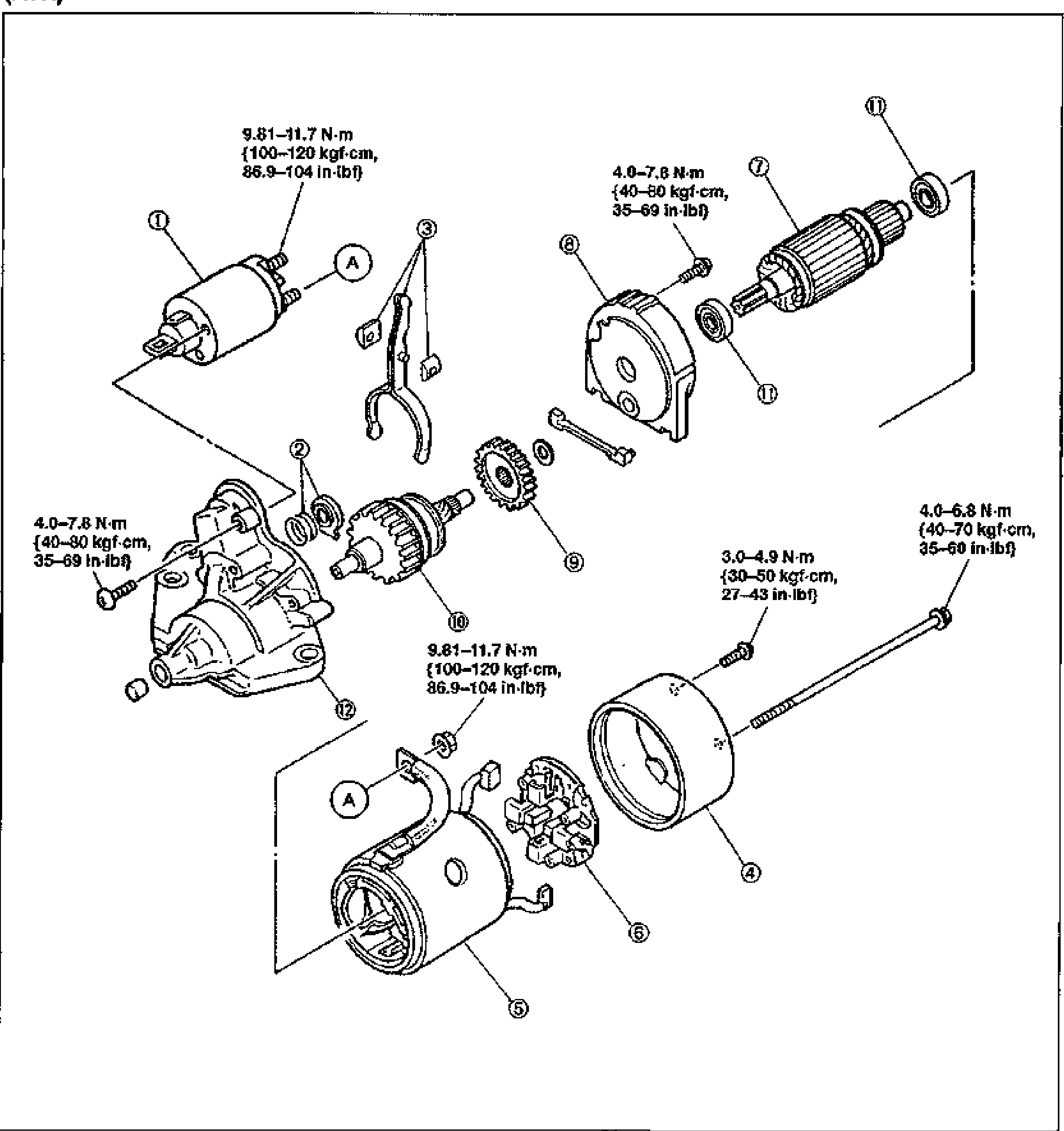
STARTING SYSTEM — STARTER Disassembly / Assembly (ATX)
G-38Exploded view of the ATX starter disassembly. Callouts: magnetic switch (1), washer (2), lever (3), rear bracket (4), yoke (5), brush holder assembly (6), armature (7), center bracket (8), internal gear (9), pinion shaft assembly / overrunning clutch (10), bearing (11), front bracket (12). Match marks 'A'. Torques: magnetic switch terminal 9.81-11.7 N·m {100-120 kgf-cm, 86.9-104 in-lbf}; through-bolts and screws 4.0-7.8 N·m {40-80 kgf-cm, 35-69 in-lbf}; 4.0-6.8 N·m {40-70 kgf-cm, 35-60 in-lbf}; 3.0-4.9 N·m {30-50 kgf-cm, 27-43 in-lbf}.
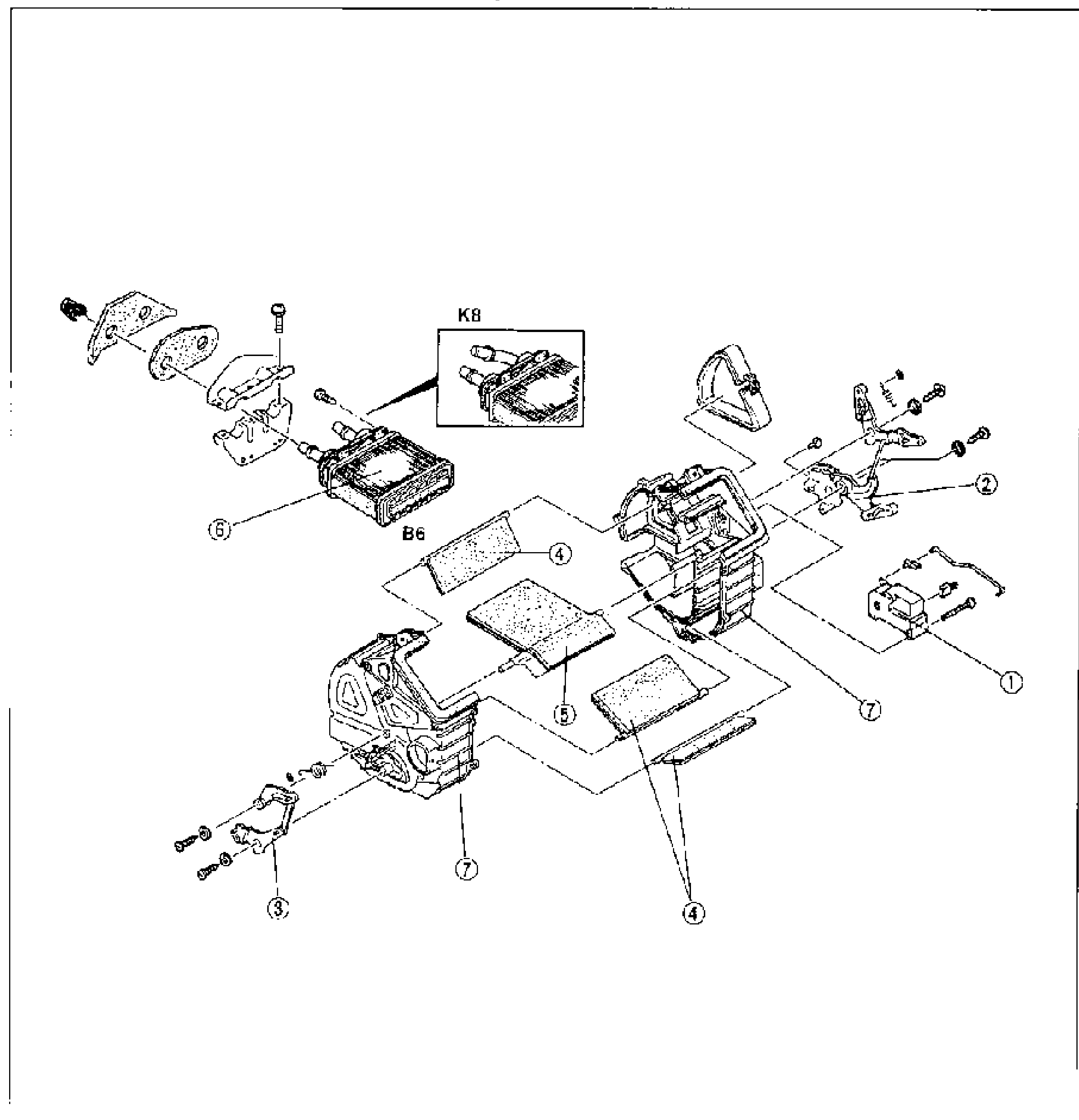
HEATER UNIT - Disassembly / Inspection / Assembly
G-38Exploded view of the heater unit. Numbered balloon callouts: 1 = Airflow mode actuator, 2 = Mode door link, 3 = Air mix link, 4 = Mode door assembly, 5 = Mix door assembly, 6 = Heater core, 7 = Heater unit case. A K8 inset (top center) shows the K8-engine heater core variant; the main heater core is labeled B6.
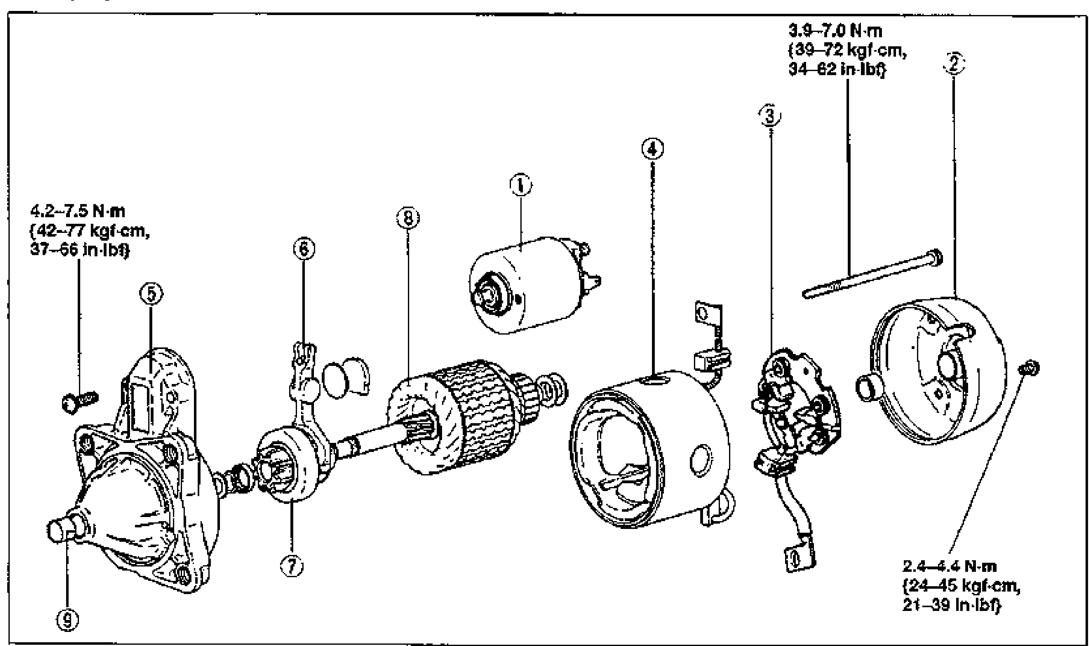
STARTING SYSTEM — STARTER Disassembly / Assembly (B6 DOHC), Drive pinion Notes
G-39Exploded view of the B6 DOHC starter disassembly. Callouts: magnetic switch (1), rear bracket (2), brush holder assembly (3), yoke (4), front bracket (5), lever (6), drive pinion (7), armature (8), bearing if equipped (9). Torques: 4.2-7.5 N·m {42-77 kgf-cm, 37-66 in-lbf}; 3.9-7.0 N·m {39-72 kgf-cm, 34-62 in-lbf}; 2.4-4.4 N·m {24-45 kgf-cm, 21-39 in-lbf}.
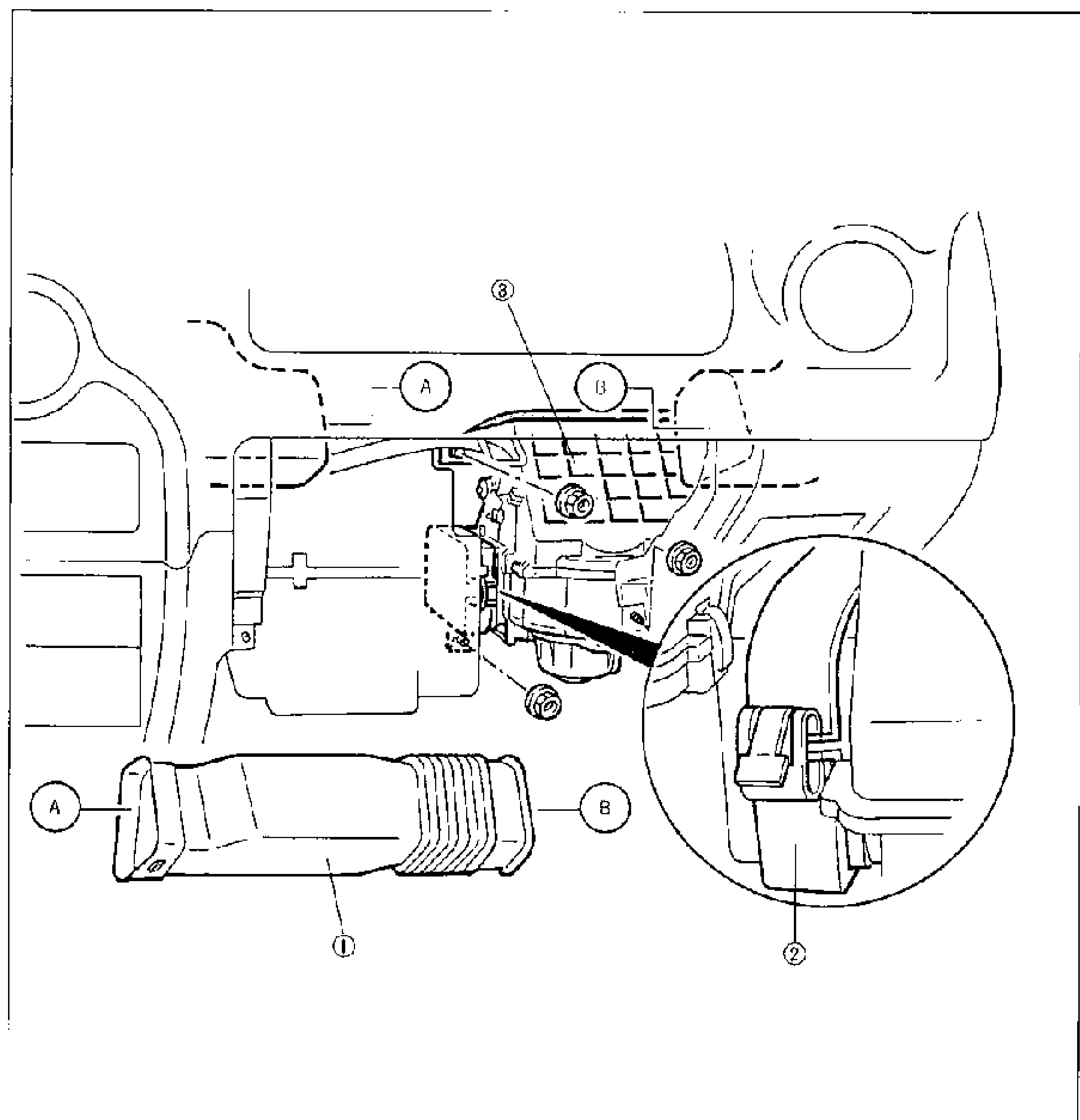
BLOWER UNIT
G-40Exploded/installation view of the heater blower unit behind the dashboard. Balloon callouts identify components: 1 = duct (lower-left, marked A and B at duct ends), 2 = seal plate (shown in a magnified circular detail at lower right of the clamp/connector), 3 = blower unit (centre, with mounting nuts). Letters A and B mark connection points between the duct and the blower assembly.
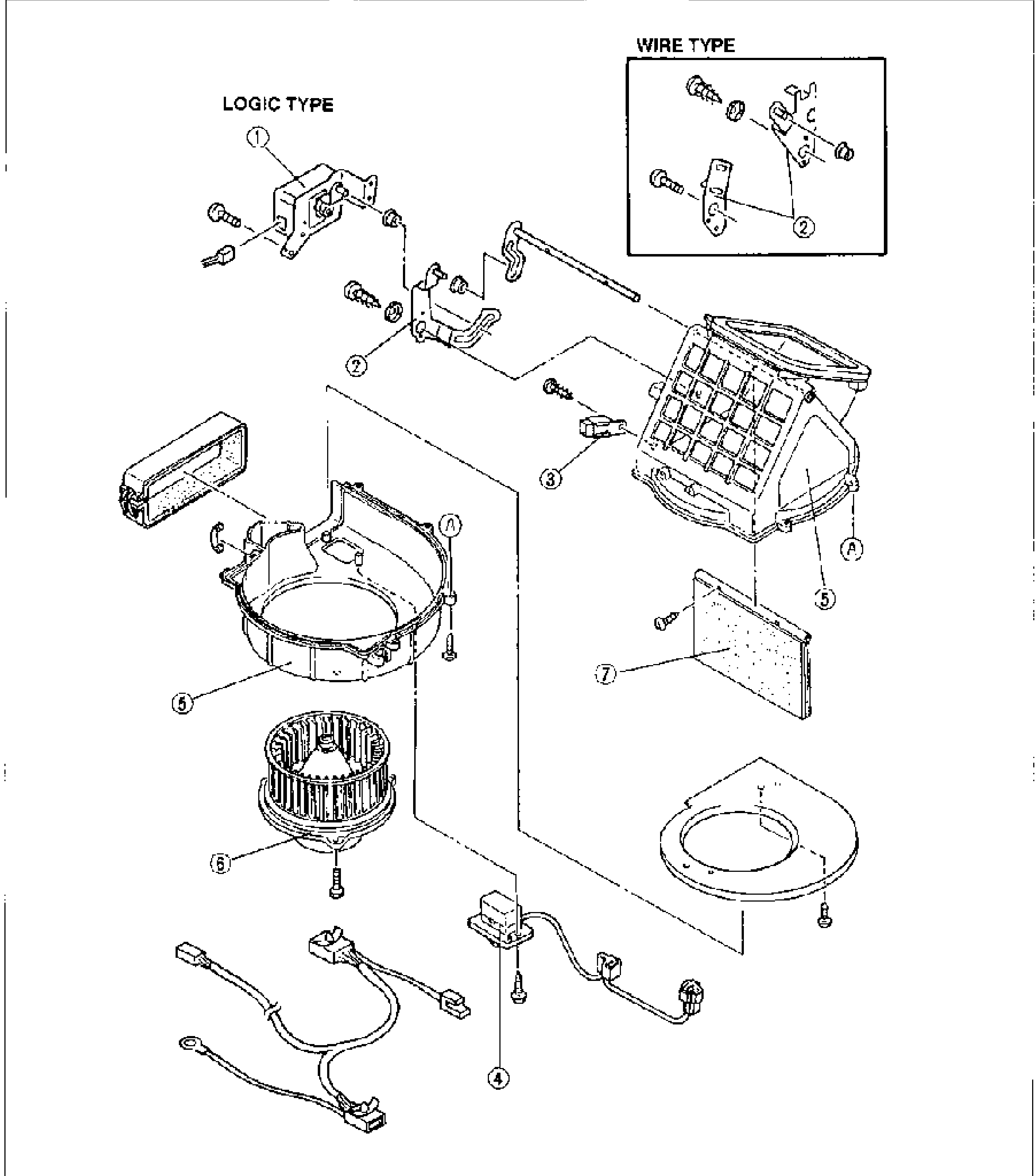
BLOWER UNIT - Disassembly / Assembly
G-41Full-page exploded view of the blower unit disassembly. Balloon callouts: 1 = air intake actuator (logic type, shown top-left labelled LOGIC TYPE; an inset top-right labelled WIRE TYPE shows the wire-type variant), 2 = intake door link, 3 = blower relay, 4 = resistor (wiring harness/connectors at bottom), 5 = blower unit case, 6 = blower motor (squirrel-cage fan), 7 = intake door assembly. Letters A mark mating points of the case halves.
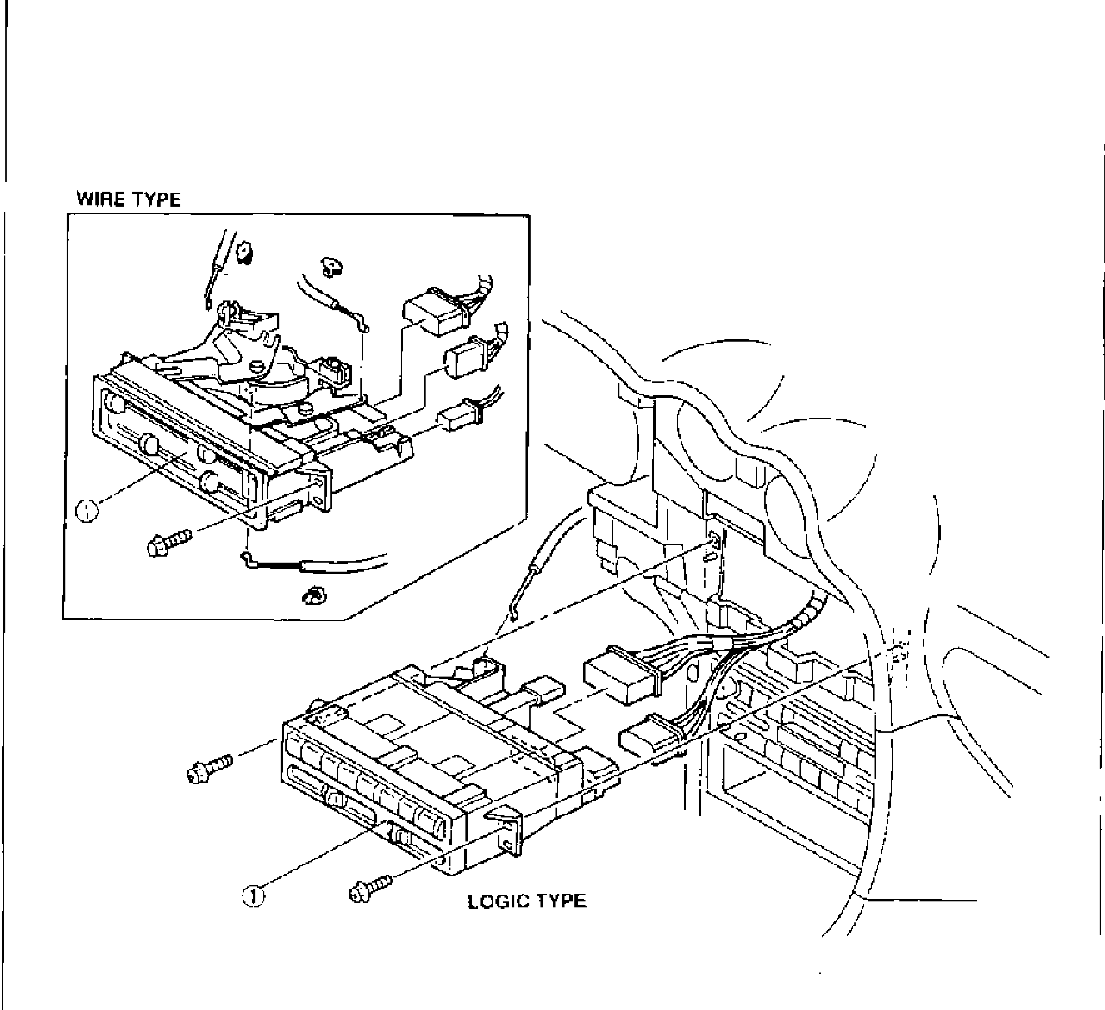
HEATER CONTROL UNIT
G-43Installation/removal view of the heater control unit mounted in the centre console/dashboard, with its connectors and harness. An inset at upper-left labelled WIRE TYPE shows the wire-type control head; the main illustration labelled LOGIC TYPE shows the logic-type control head with mounting screws. Balloon callout 1 marks the heater control unit on both variants.
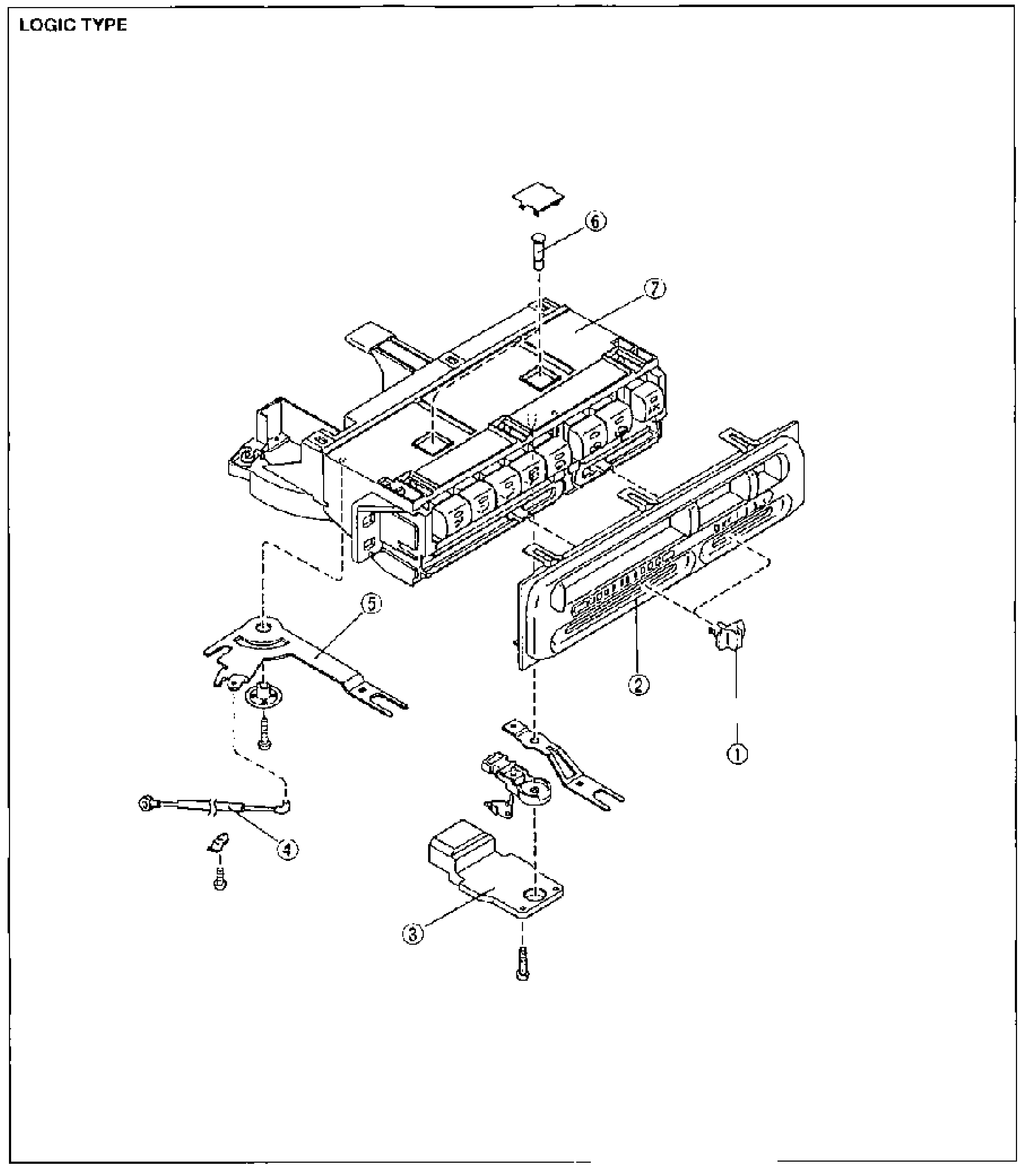
HEATER CONTROL UNIT - Disassembly / Assembly
G-44Full-page exploded view of the LOGIC TYPE heater control unit disassembly. Balloon callouts: 1 = knob, 2 = switch panel, 3 = fan switch, 4 = air mix wire, 5 = temperature control lever, 6 = bulb, 7 = heater control unit (main body). Screws shown at mating points.
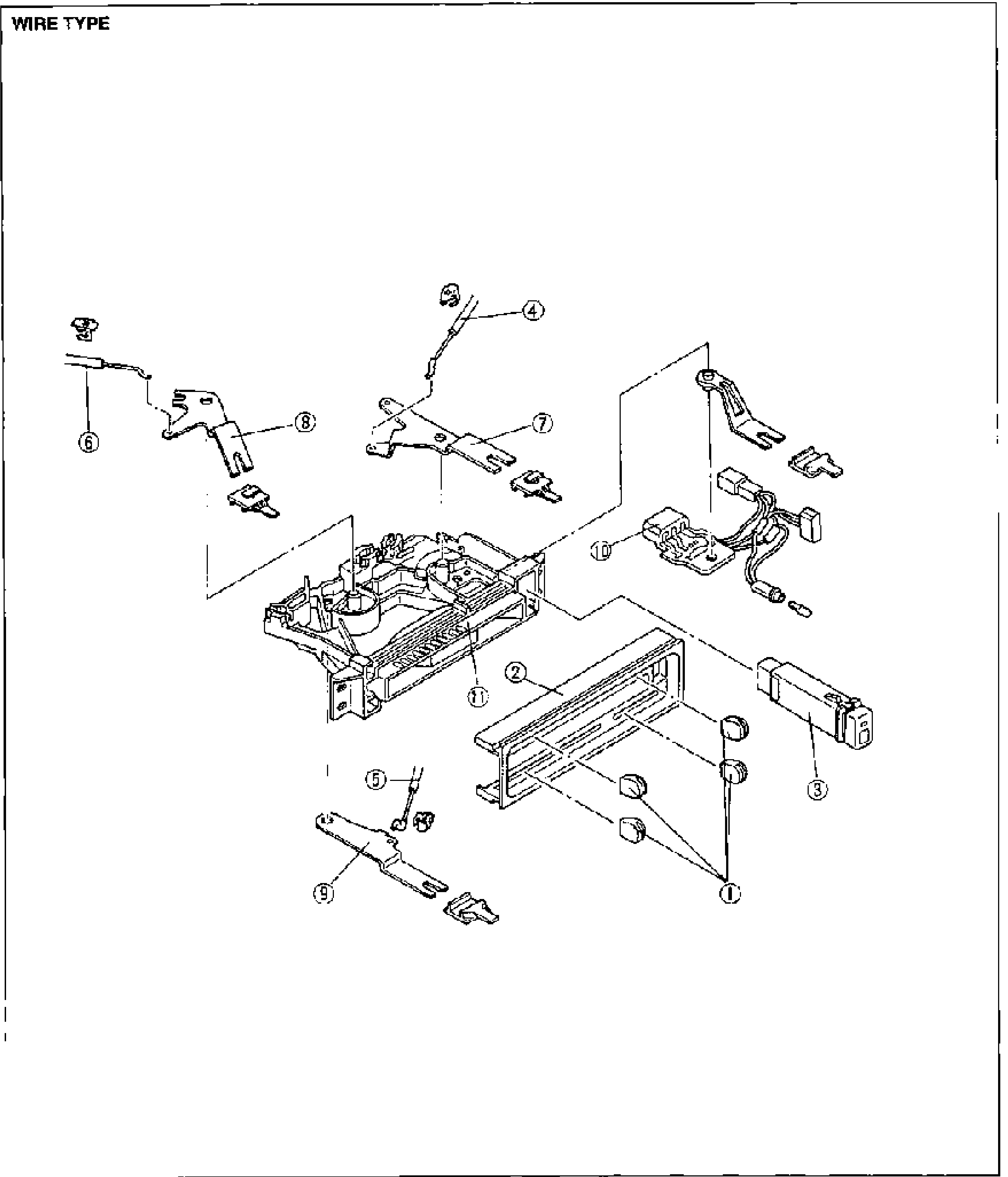
HEATER CONTROL UNIT - Disassembly / Assembly (Wire Type)
G-45Full-page exploded view of the WIRE TYPE heater control unit disassembly. Balloon callouts: 1 = knob, 2 = switch panel, 3 = A/C switch, 4 = air intake wire, 5 = airflow mode wire, 6 = air mix wire, 7 = REC/FRESH lever, 8 = mode lever, 9 = temperature control lever, 10 = fan switch, 11 = heater control unit (main body).
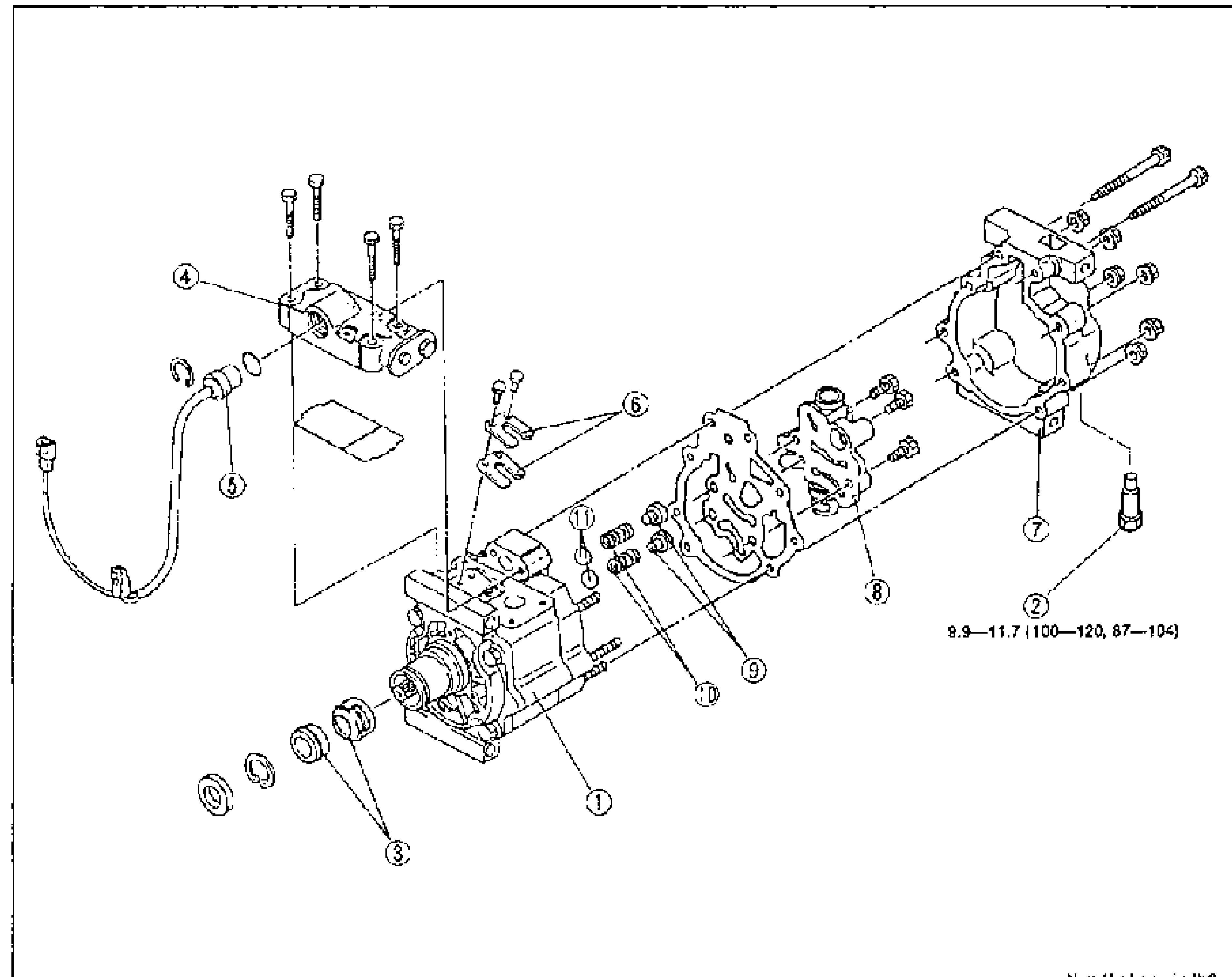
A/C COMPRESSOR — Disassembly / Assembly
G-56Exploded view of the A/C compressor laid out horizontally with numbered balloon callouts 1-11 from front (shaft seal end, left) to rear case (right). Bolts are torqued; the rear-case bolts show torque 8.9-11.7 N.m (100-120 kgf.cm, 87-104 in-lbf). Units note at bottom right: N.m {kgf.cm, in-lbf}.
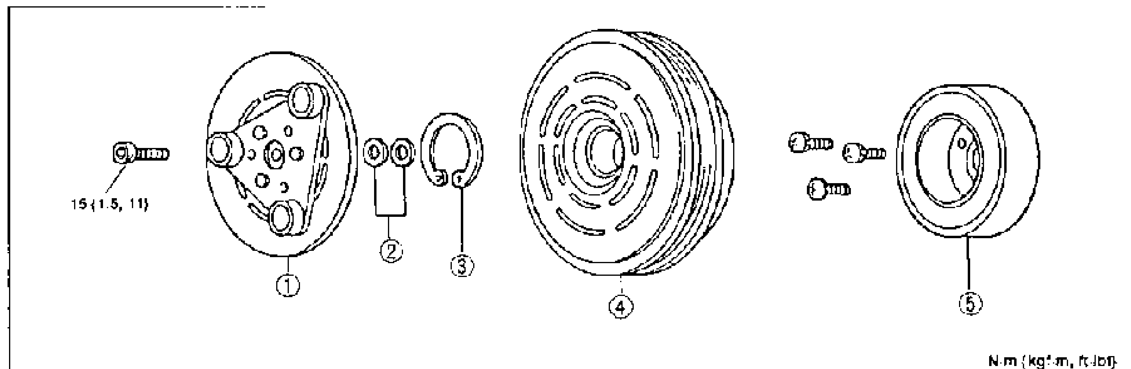
AIR CONDITIONER — Magnetic Clutch Disassembly / Assembly
G-62Exploded view of the magnetic clutch assembly, left to right: pressure plate retaining bolt (15 N·m), pressure plate (1), shim (2), snap ring (3), rotor pulley (4), and stator (5). Balloon callouts 1-5 identify each part; tightening torque 15 {1.5, 11} marked on the bolt.

AIR CONDITIONER — Condenser
G-64Engine-bay line drawing of the condenser removal. Left view shows the condenser brackets being removed (callout 1, condenser bracket); a large arrow points to the right view showing the condenser (callout 2) lifted out from in front of the radiator.
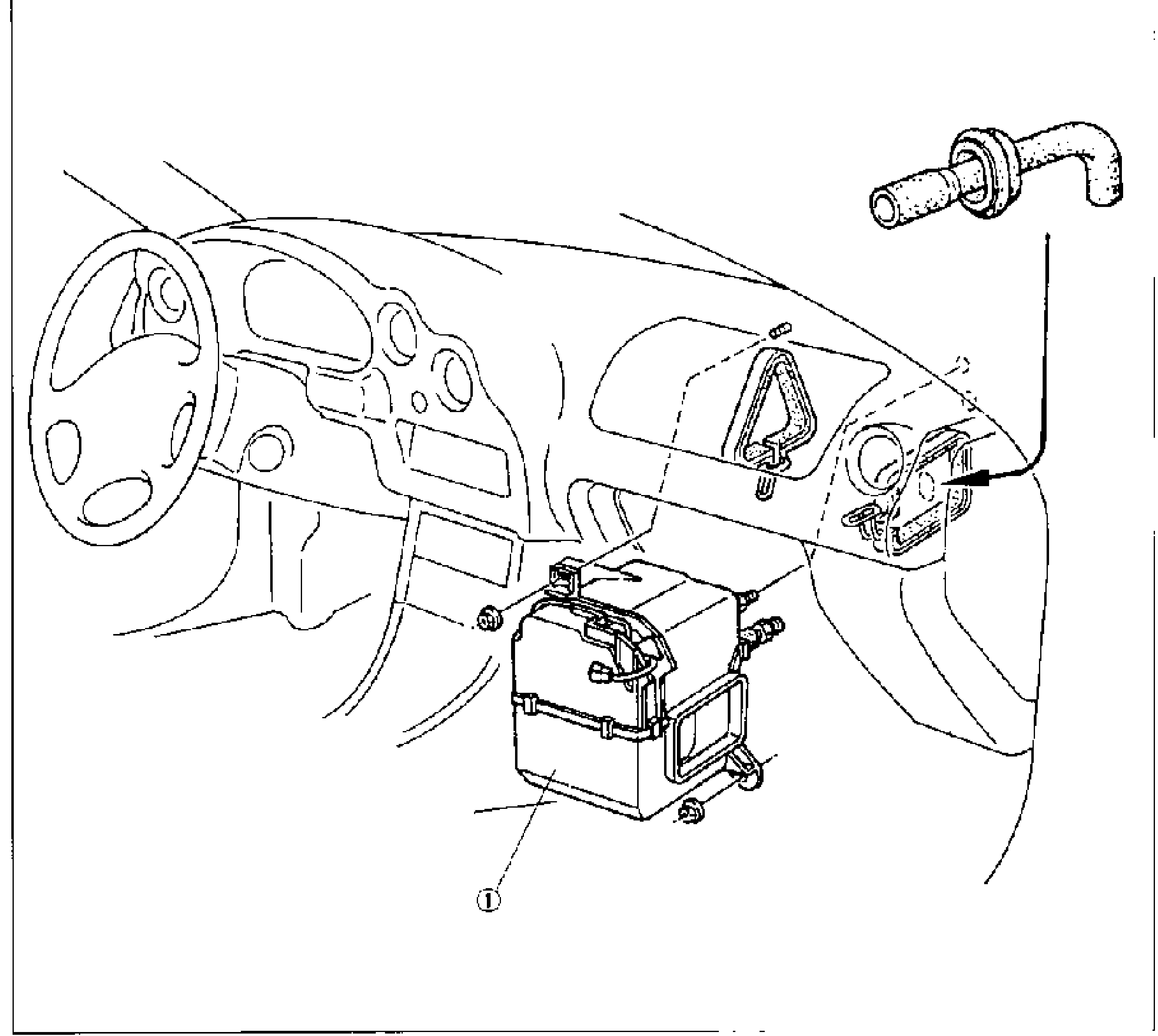
AIR CONDITIONER — Cooling Unit
G-67Line drawing of the dashboard/instrument panel area with the cooling unit (evaporator unit) shown removed from below the dash, callout 1. An inset at upper right shows a cooler pipe fitting/O-ring detail. Steering wheel and dash structure are drawn for reference.
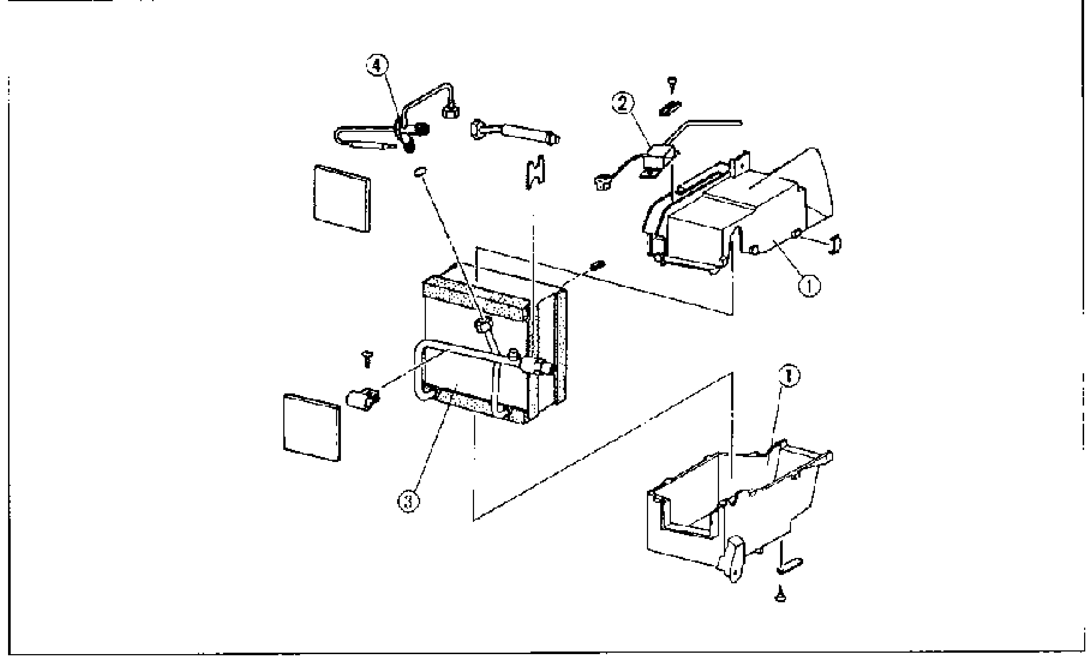
AIR CONDITIONER — Cooling Unit Disassembly / Assembly
G-68Exploded view of the cooling unit. Balloon callouts: 4 = expansion valve (with piping at top left), 2 = thermoswitch (top right), 3 = evaporator core (center), 1 = cooling unit case (the upper and lower case halves at right). Insulation pads, screws and clips are shown around the evaporator core.
Clutch
H7 diagrams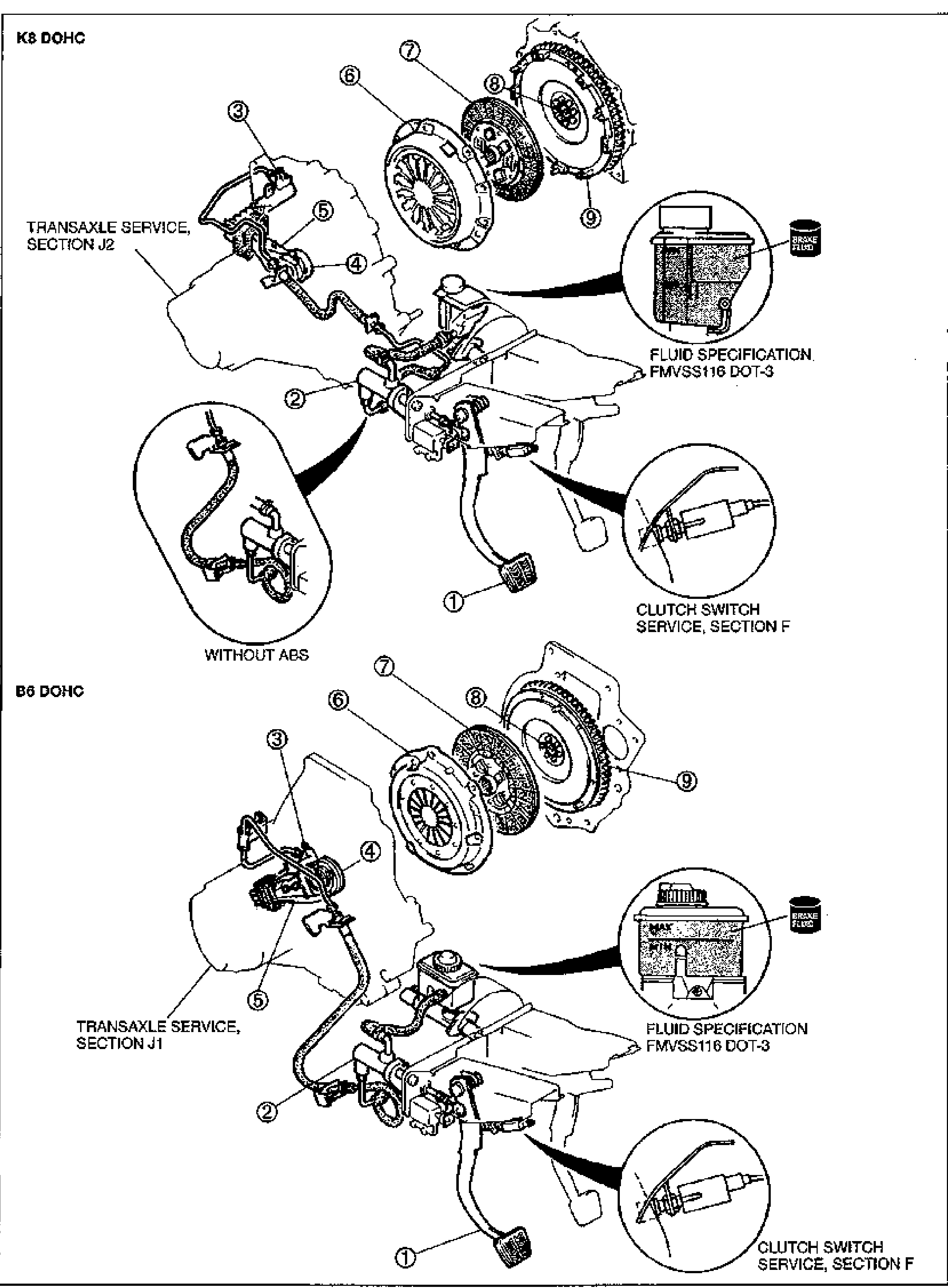
INDEX
H-2Exploded index view of the clutch system covering two engine variants. Top half labeled 'K8 DOHC' shows the clutch master cylinder, pipe, release/slave cylinder, clutch cover (6), clutch disc (7), flywheel (8) and pilot/ring gear area (9), with the transaxle (Section J2). Inset circles show the 'WITHOUT ABS' pedal/master cylinder routing, the brake-fluid reservoir (FLUID SPECIFICATION FMVSS116 DOT-3) and the CLUTCH SWITCH SERVICE, SECTION F. Bottom half labeled 'B6 DOHC' shows the same clutch components with the transaxle (Section J1), a brake-fluid reservoir inset (MAX/MIN level), the clutch pedal/master cylinder (1, 2) and CLUTCH SWITCH SERVICE, SECTION F inset. Numbered callouts 1-9 identify pedal, master cylinder, pipe, release components, clutch cover, disc, flywheel and related parts.
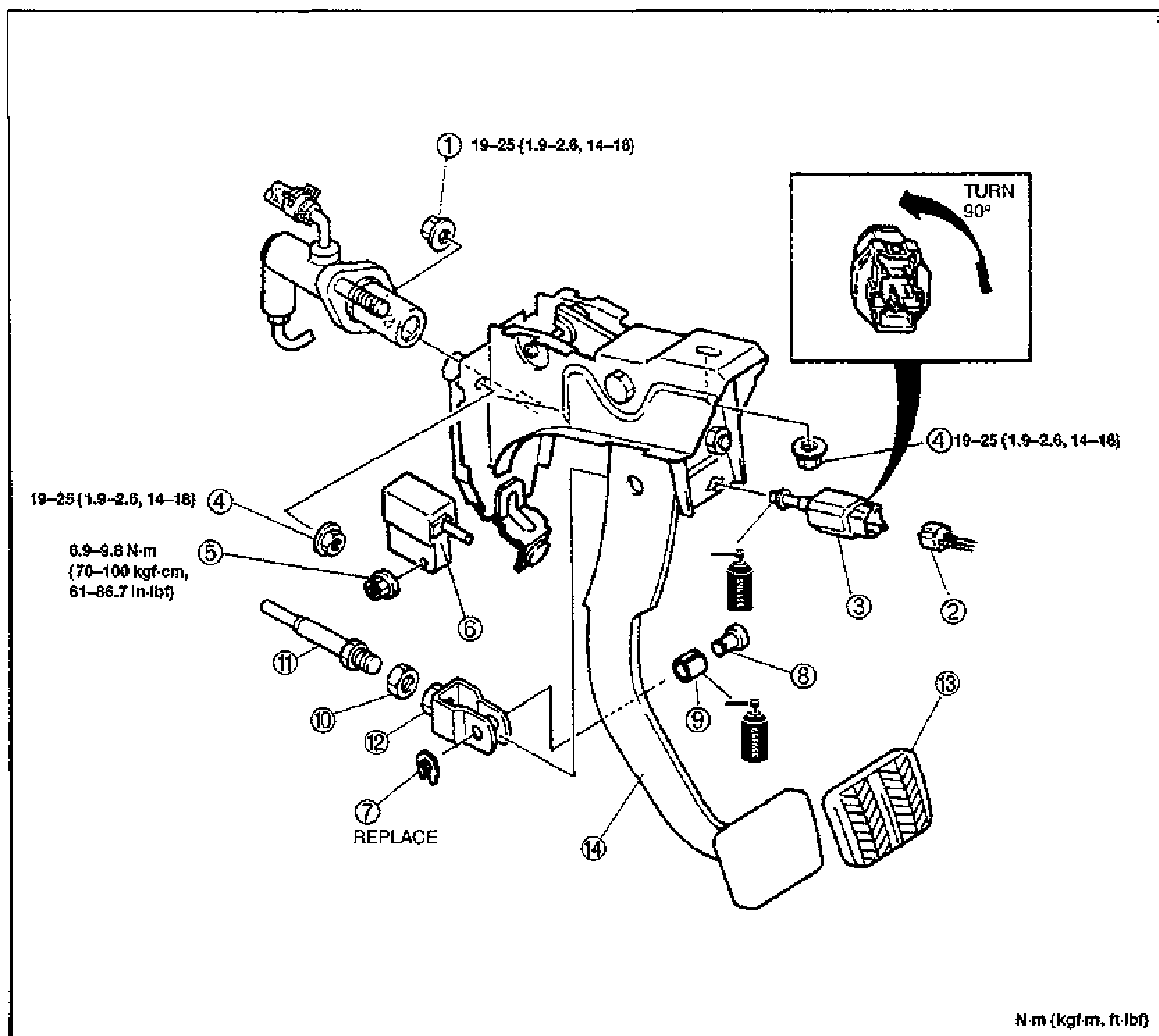
CLUTCH PEDAL
H-7Exploded view of the clutch pedal assembly with the pedal bracket. Numbered balloons 1-14 identify the master cylinder mounting nuts, clutch switch and connector, starter interlock switch, push rod, clevis, pin, clip, bushing, pedal pad and clutch pedal. An inset at upper right shows the clutch switch with a 'TURN 90°' rotation arrow for installation. Torque callouts: nuts (1) and (4) 19—25 N·m {1.9—2.6 kgf·m, 14—18 ft·lbf}; nut (5) 6.9—9.8 N·m {70—100 kgf·cm, 61—86.7 in·lbf}. Grease symbols indicate lubrication points; clip (7) marked REPLACE. Torque unit note: N·m {kgf·m, ft·lbf}.
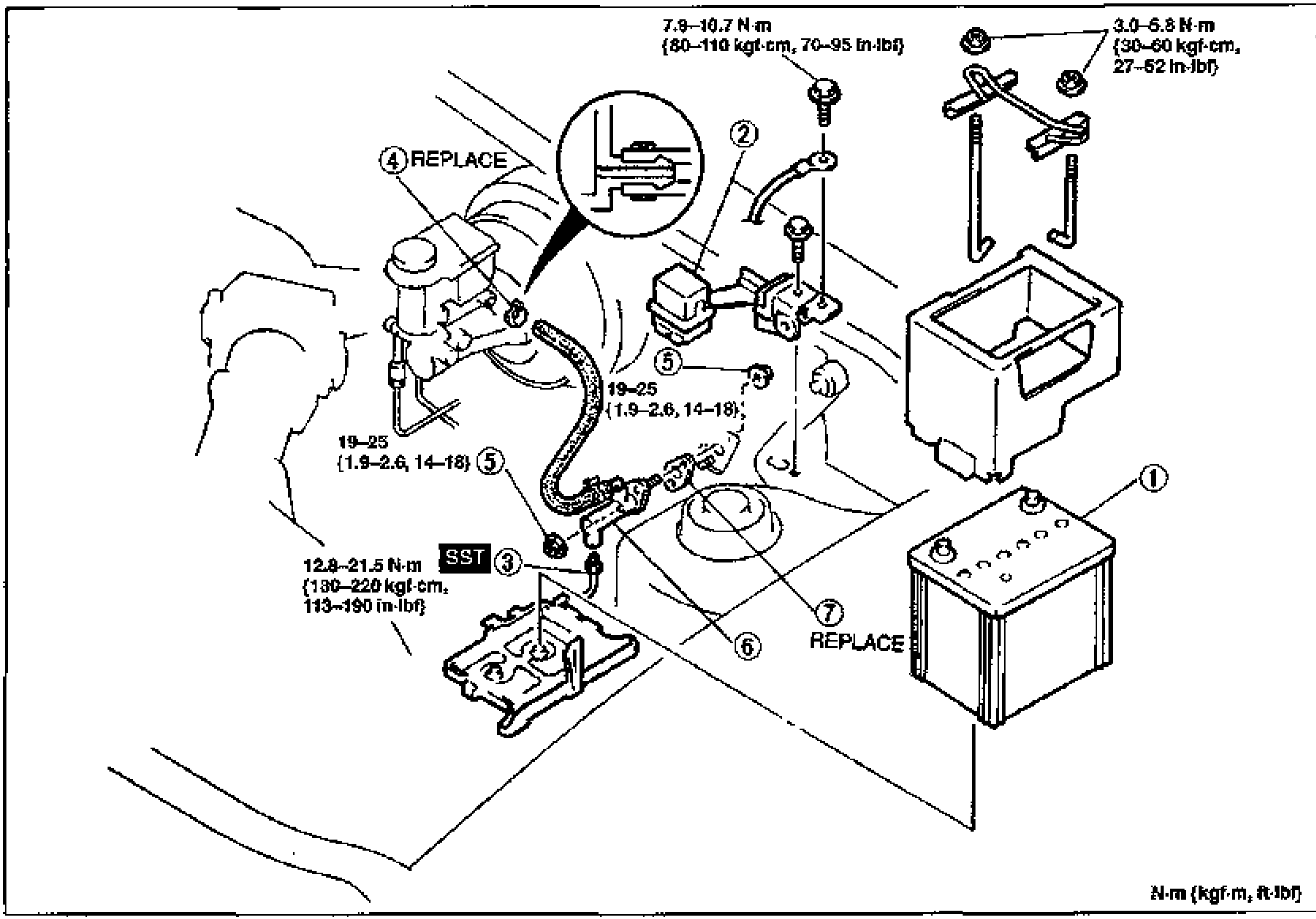
CLUTCH MASTER CYLINDER
H-8Exploded view of the clutch master cylinder installation in the engine bay. Numbered balloons 1-7 identify the battery, data link connector, clutch pipe, clip, nut, clutch master cylinder and gasket. An inset shows the SST flare-nut wrench engaging the clutch pipe flare fitting. Torque callouts: nuts (5) 19—25 N·m {1.9—2.6 kgf·m, 14—18 ft·lbf}; nut (2) area 7.9—10.7 N·m {80—110 kgf·cm, 70—95 in·lbf}; battery bracket nuts 3.0—6.8 N·m {30—60 kgf·cm, 27—52 in·lbf}; clutch pipe flare fitting (3, SST) 12.8—21.5 N·m {130—220 kgf·cm, 113—190 in·lbf}. Clip (4) and gasket (7) marked REPLACE. Torque unit note: N·m {kgf·m, ft·lbf}.
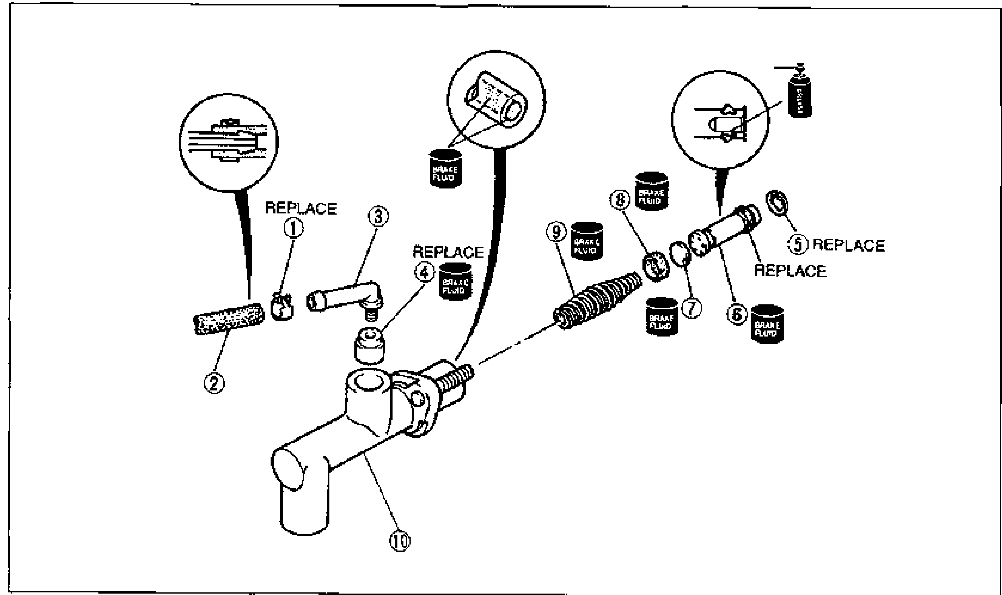
CLUTCH MASTER CYLINDER
H-11Exploded view of the clutch master cylinder for overhaul. Numbered balloons 1-10 identify the clip, hose, joint, bushing, snap ring, piston and secondary cup assembly, spacer, primary cup, return spring and master cylinder body, shown in disassembly order along the cylinder bore axis. Inset detail circles show the clip engagement, bushing/joint and snap-ring fitting. Brake-fluid (clutch fluid) application symbols mark several internal parts; items (1), (4) and (5) marked REPLACE.
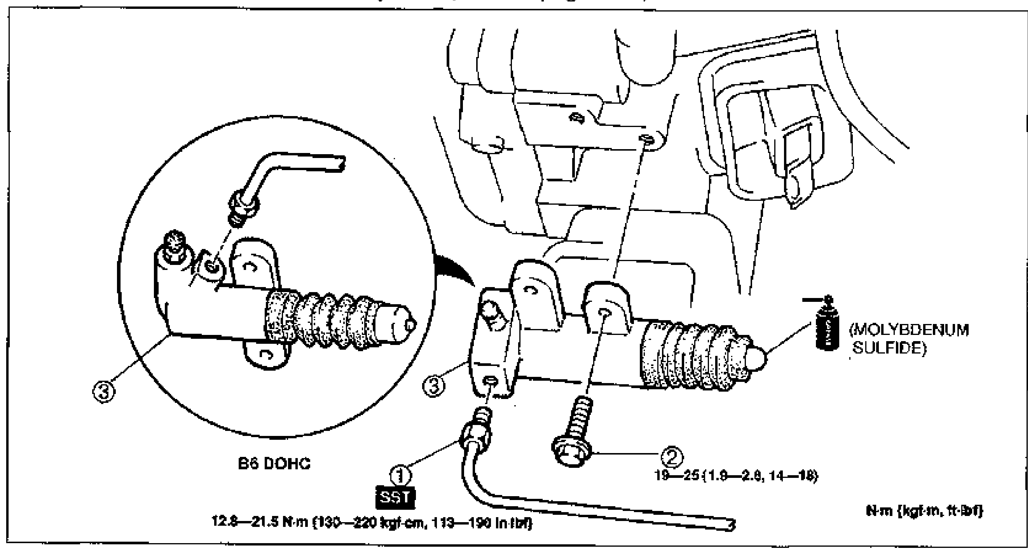
Clutch Release Cylinder
H-13Exploded view of the clutch release cylinder installation (B6 DOHC). A magnified inset at left shows the release cylinder with bleeder screw; callout 3 points to the clutch release cylinder, callout 1 (with SST) to the clutch pipe with torque 12.6-21.5 N·m (130-220 kgf·cm, 113-190 in-lbf), callout 2 to the mounting bolt with torque 19-25 N·m (1.9-2.6 kgf·m, 14-18 ft-lbf). A molybdenum sulfide grease application point is indicated at the cylinder rod tip.
Clutch Release Cylinder
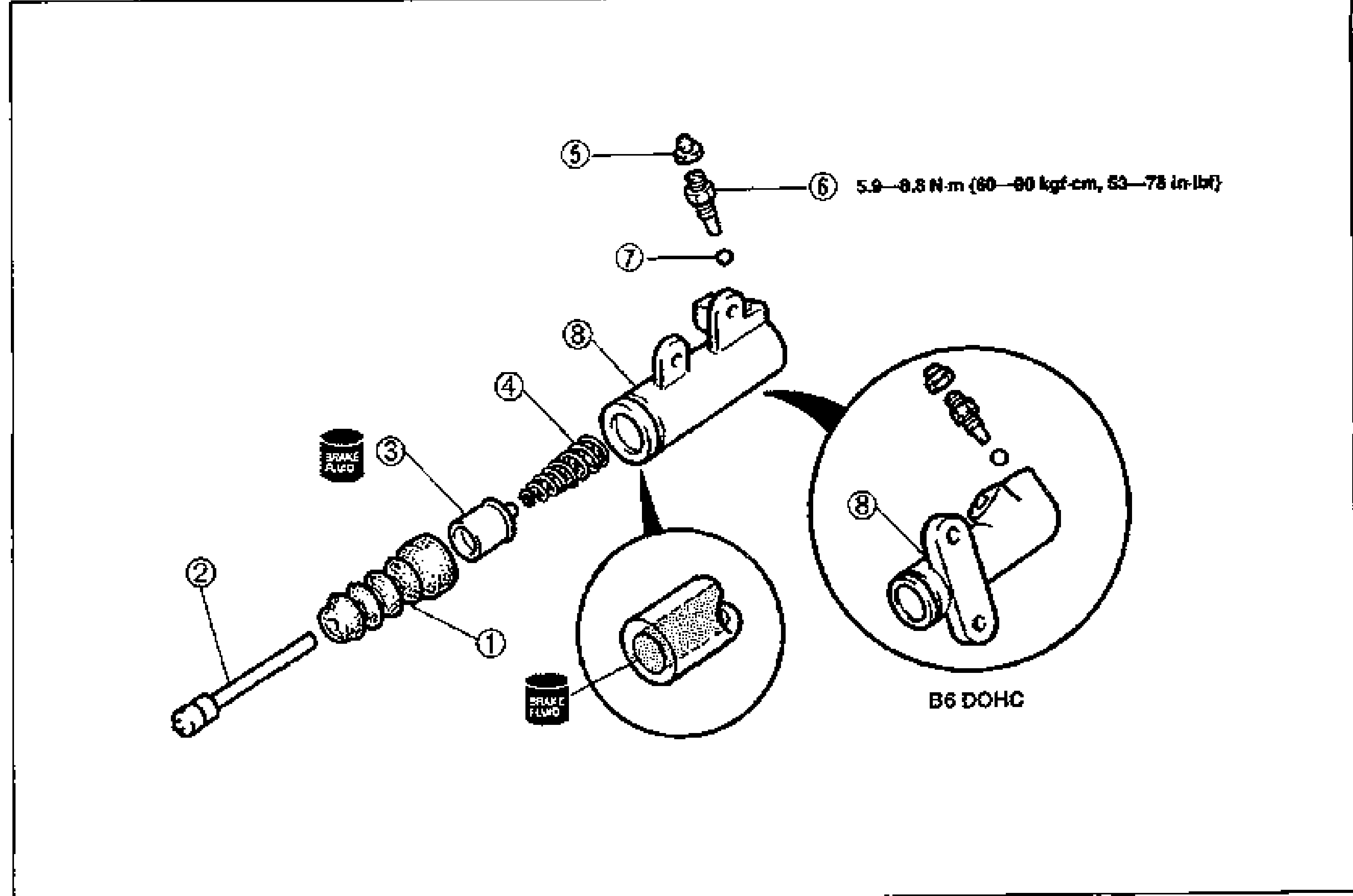
H-14Exploded view of the clutch release cylinder (B6 DOHC) disassembly order. Numbered callouts 1-8: push rod, boot, piston and cup assembly, return spring, bleeder cap, bleeder screw, steel ball, release cylinder body. Two magnified insets show the piston/cup with brake fluid application and the release cylinder body. Bleeder screw torque 5.9-8.8 N·m (60-90 kgf·cm, 53-78 in-lbf).
Clutch Unit
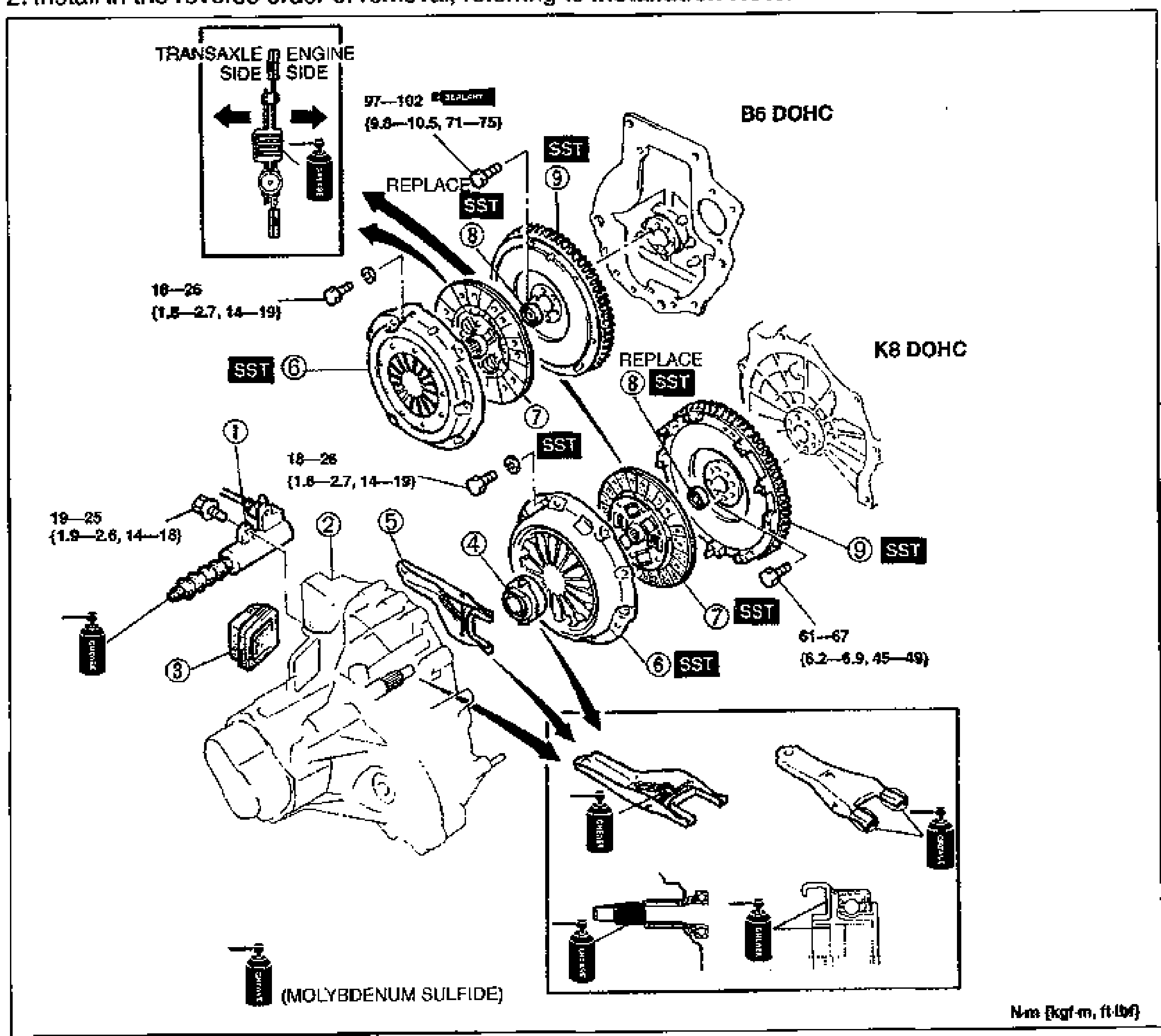
H-16Large exploded view of the clutch unit removal/installation for B6 DOHC and K8 DOHC engines. Numbered callouts 1-9: clutch release cylinder, transaxle, boot, clutch release collar, clutch release fork, clutch cover, clutch disc, pilot bearing, flywheel. SST markers and REPLACE indicators are shown at several joints. An inset top-left shows transaxle side vs engine side orientation with molybdenum sulfide grease application. Torque values: 97-102 N·m (9.8-10.5 kgf·m, 71-75 ft-lbf) for the flywheel, 18-26 N·m (1.8-2.7 kgf·m, 14-19 ft-lbf) and 19-25 N·m (1.9-2.6 kgf·m, 14-18 ft-lbf) at clutch fasteners, 61-67 N·m (6.2-6.9 kgf·m, 45-49 ft-lbf) at the K8 flywheel. Lower inset shows clutch release fork grease points (molybdenum sulfide).
Manual Transaxle (G25M-R)
J29 diagrams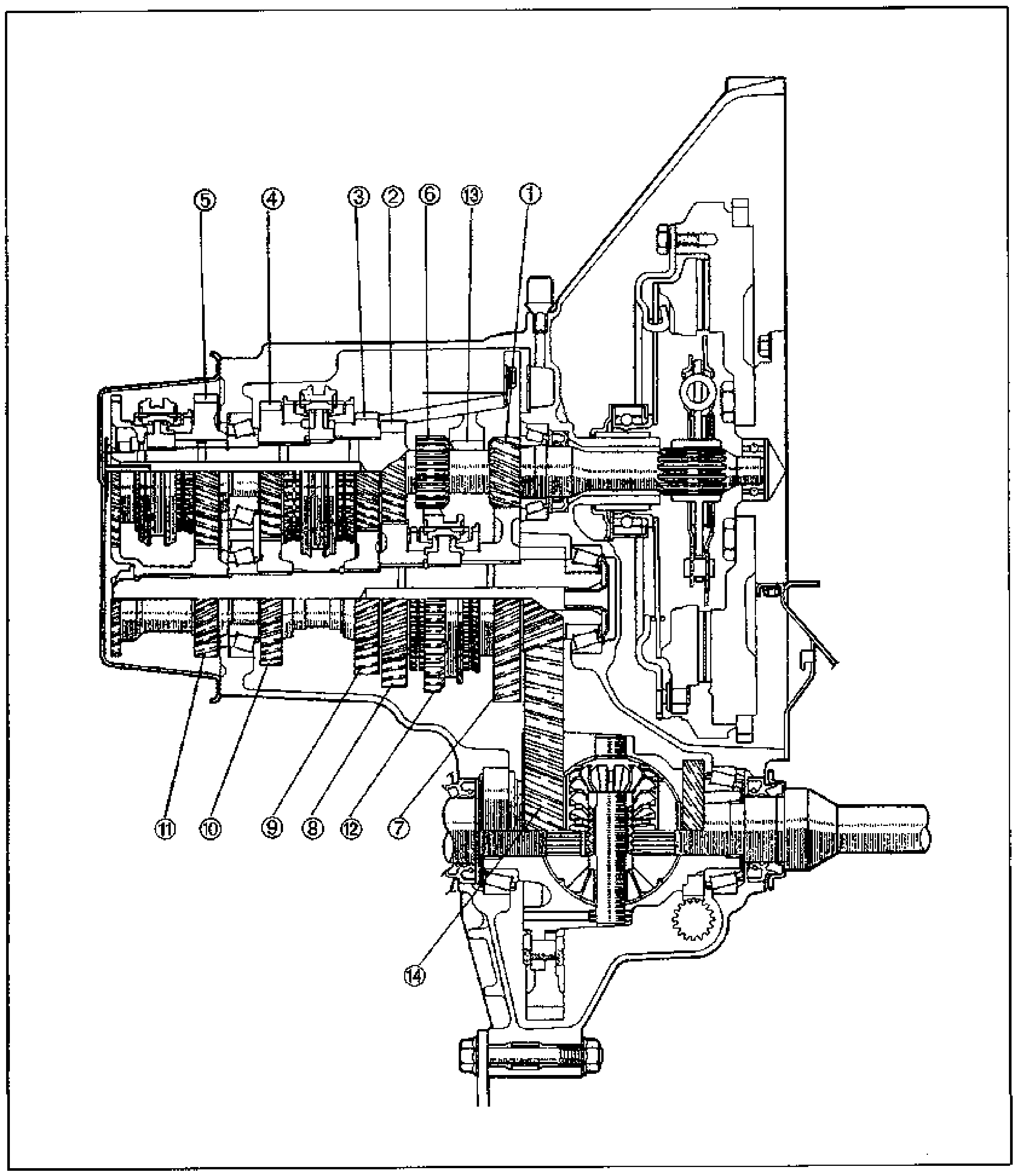
OUTLINE — STRUCTURAL VIEW
J2-4Sectional (cutaway) structural view of the manual transaxle showing the gear train, shafts, synchronizers, differential and clutch housing. Fourteen leader-line callouts identify the gears and components: input/secondary gears (1-13) along the top shafts and the differential (14) at lower center.
Primary Shaft Assembly
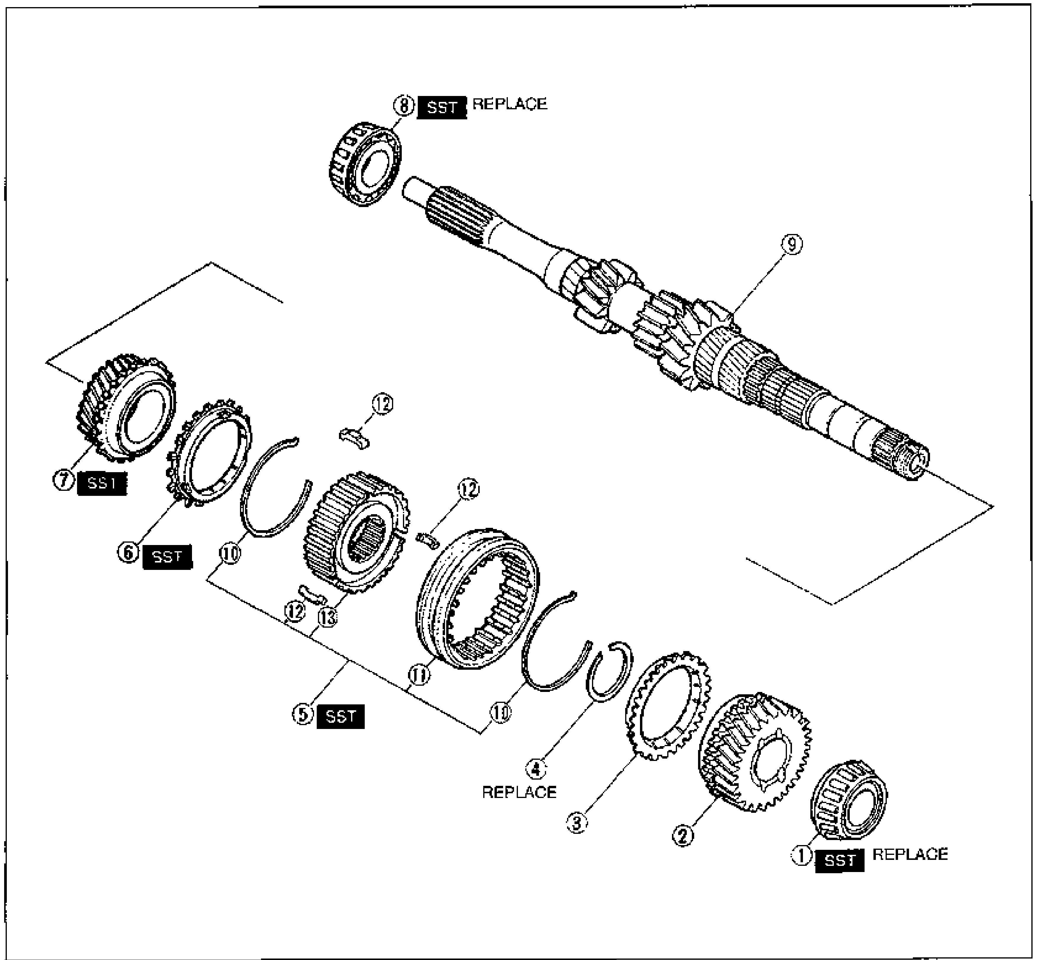
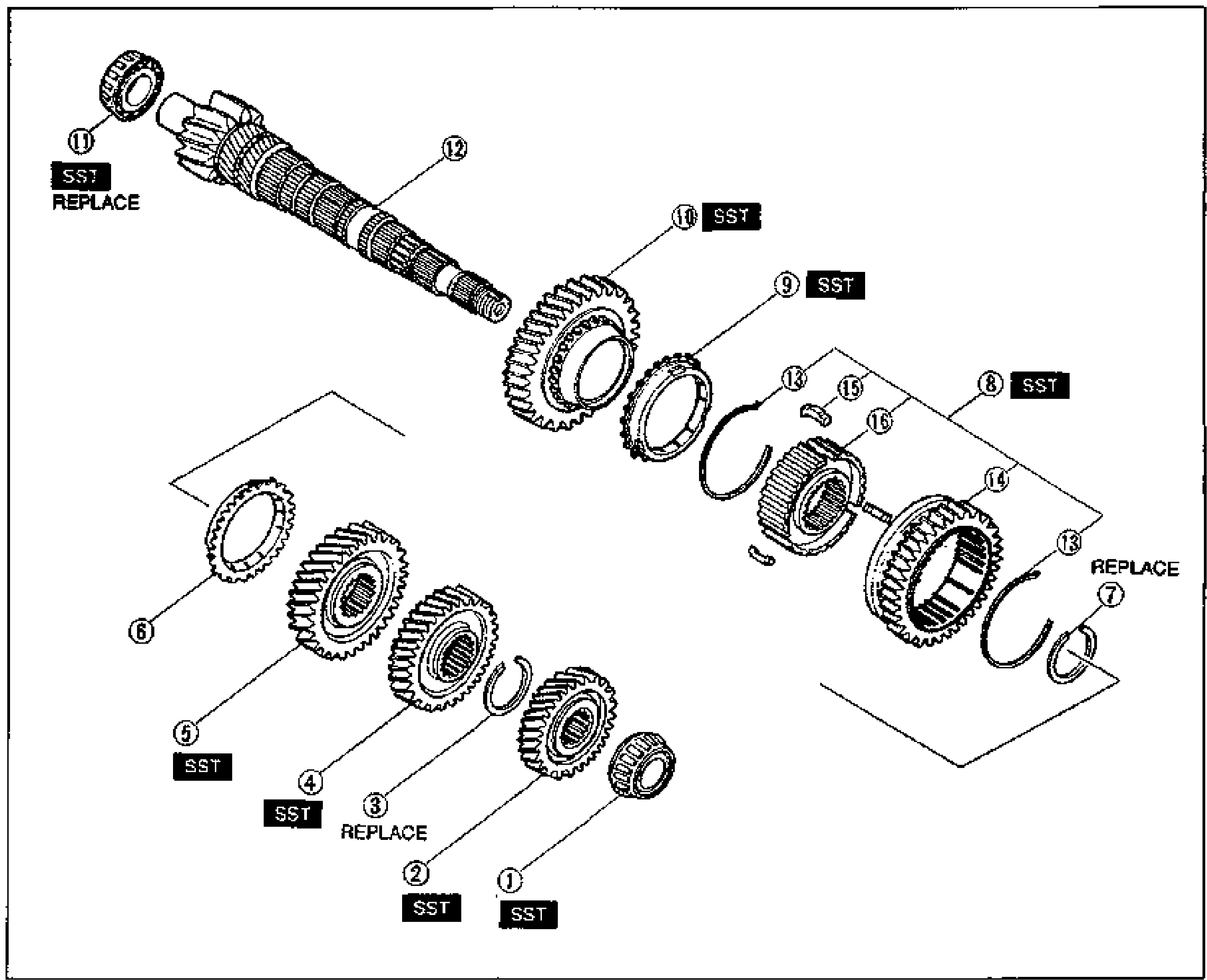
J2-22Exploded view of the manual transaxle primary shaft assembly. The primary shaft gear (9) runs diagonally from upper-right; components are laid out for disassembly order. From upper-left: bearing primary shaft end (8, marked SST/REPLACE), then the 3rd-gear cluster including 3rd gear (7, SST), 3rd synchronizer ring (6, SST), 3rd/4th clutch hub assembly (5, SST), synchronizer key spring (10), 3rd/4th clutch hub sleeve (11), synchronizer keys (12), 3rd/4th clutch hub (13), retaining ring (4, REPLACE), 4th synchronizer ring (3), 4th gear (2), and bearing 4th-gear end (1, SST/REPLACE).
Secondary Shaft Assembly
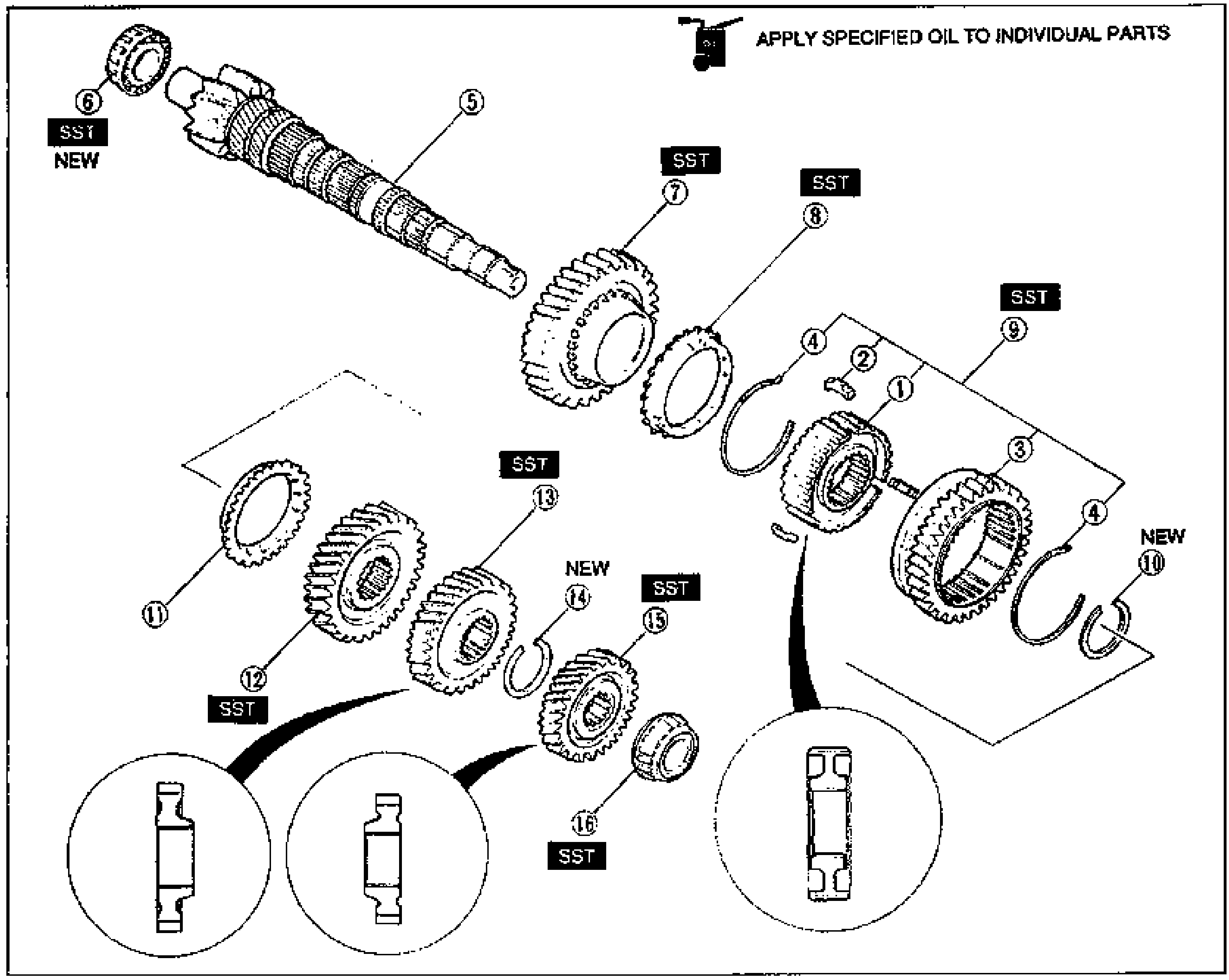
J2-24Exploded view of the manual transaxle secondary shaft assembly with 16 numbered balloon callouts. The secondary shaft gear (12) runs diagonally from upper-left. Components shown include bearing secondary shaft end (11, SST/REPLACE), 1st gear (10, SST), 1st synchronizer ring (9, SST), 1st/2nd clutch hub assembly (8, SST), synchronizer key spring (13), clutch hub sleeve/reverse gear (14), synchronizer key (15), 1st/2nd clutch hub (16), and the lower row: 2nd synchronizer ring (6), 2nd gear (5, SST), secondary 3rd gear (4, SST), retaining ring (3, REPLACE), secondary 4th gear (2, SST), bearing (1, SST), and retaining ring (7).
Assembly - Secondary Shaft Assembly
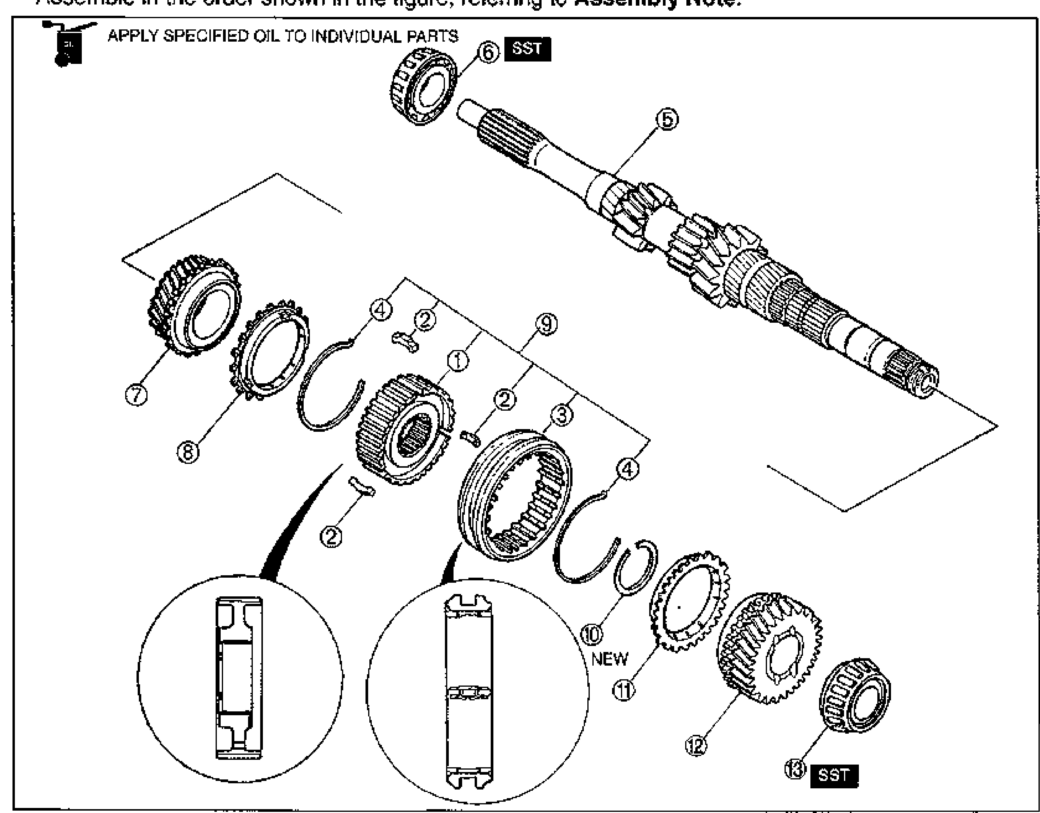
J2-30Exploded assembly view of the manual transaxle secondary shaft with 16 numbered balloon callouts and an 'APPLY SPECIFIED OIL TO INDIVIDUAL PARTS' oil-can note. The secondary shaft gear (5) runs from upper-left with bearing secondary shaft end (6, SST/NEW). Components include 1st gear (7, SST), 1st synchronizer ring (8, SST), 1st/2nd clutch hub assembly (9, SST), retaining ring (10, NEW), synchronizer key spring (4), synchronizer key (2), 1st/2nd clutch hub (1), clutch hub sleeve/reverse gear (3), and lower row: 2nd synchronizer ring (11), 2nd gear (12, SST), secondary 3rd gear (13, SST), retaining ring (14, NEW), secondary 4th gear (15, SST), and bearing (16, SST). Three inset detail circles at the bottom show clutch hub orientation features.
TRANSAXLE — Primary Shaft Assembly
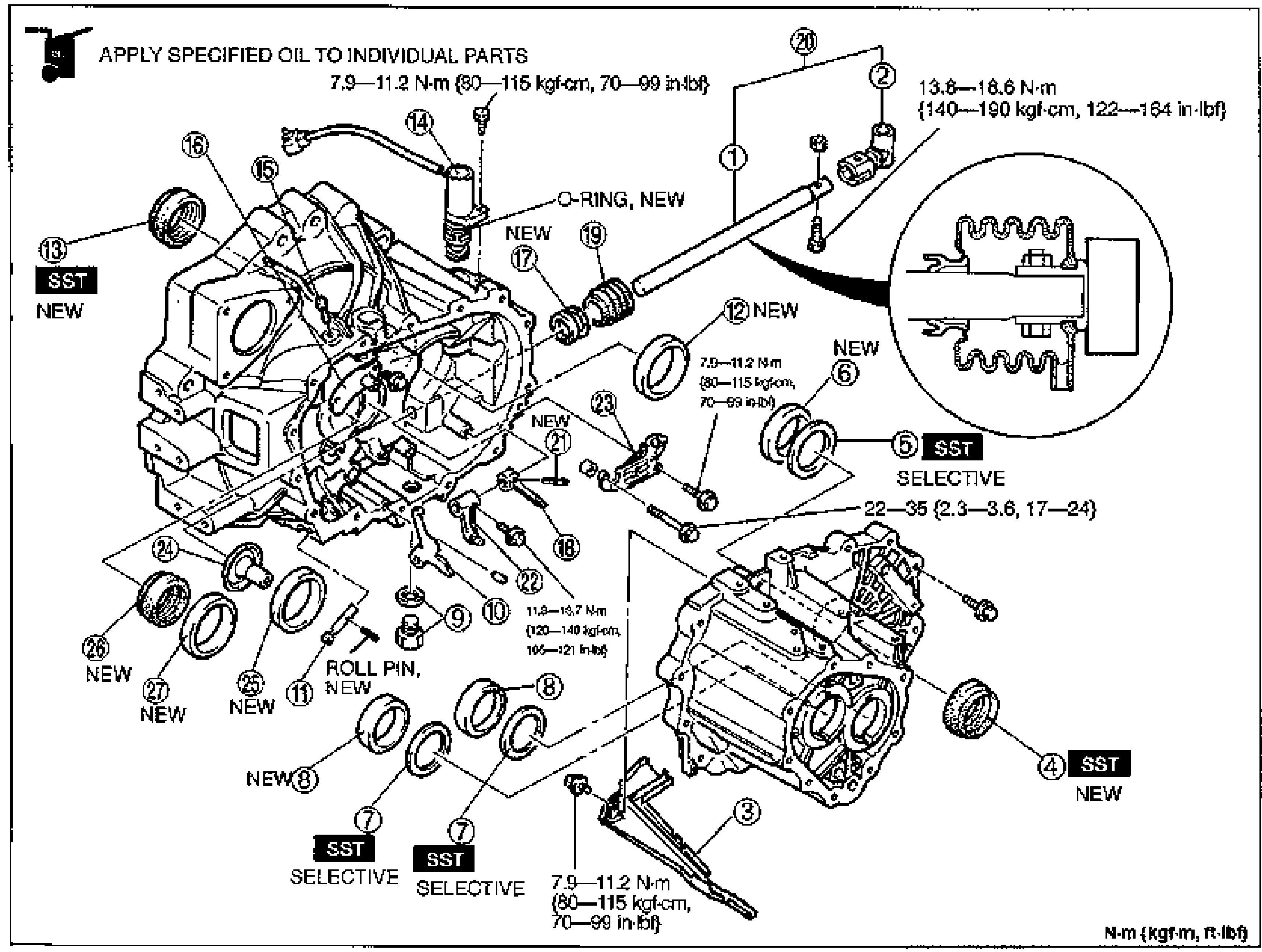
J2-33Exploded view of the primary shaft assembly, arranged in assembly order with numbered balloon callouts 1-13. Primary shaft gear (5) at top right; components are exploded out toward the lower left. 'APPLY SPECIFIED OIL TO INDIVIDUAL PARTS' oil-can symbol at top left; SST symbols at items 6 and 13. Two circular detail insets at lower left show the 3rd/4th clutch hub sleeve and synchronizer key orientation. Retaining ring (10) marked NEW.
TRANSAXLE — Clutch Housing and Transaxle Case Components
J2-35Exploded view of the clutch housing and transaxle case components with numbered balloon callouts 1-27. The clutch housing is at left and the transaxle case at lower right. 'APPLY SPECIFIED OIL TO INDIVIDUAL PARTS' oil-can symbol at top left. Several parts marked NEW (O-ring, oil seals, bearing races) and SST/SELECTIVE (adjustment shims, bearing races). A circular detail inset upper-right shows the boot installation. Torque values annotated at multiple fasteners.
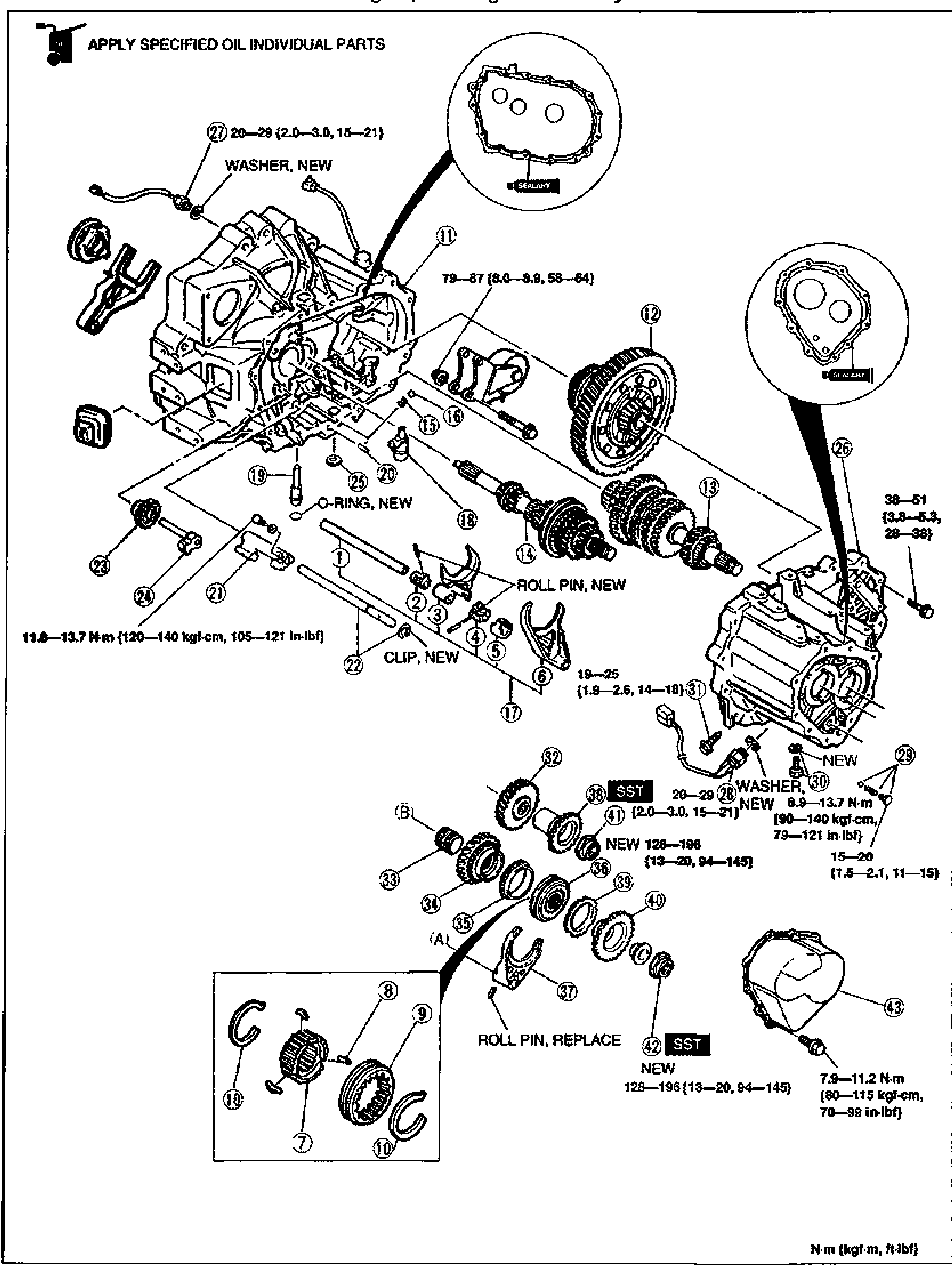
5th/Reverse Gear and Housing Parts
J2-42Exploded view of the 5th/reverse gear and transaxle housing assembly. Shows the transaxle clutch housing (upper left) and rear/case housing (right), with shift forks, shafts, the differential ring gear (12), the 5th gear cluster (13/14) and idler shafts. A separate framed sub-detail at lower-left shows synchronizer hub parts (7, 8, 9, 10). Two callout circles at top show the sealant application pattern on the housing mating faces (callouts 11 and 26). Tightening torques are printed beside several fasteners; balloons numbered 1-43 identify the assembly sequence. Notes mark WASHER NEW, O-RING NEW, ROLL PIN NEW/REPLACE, CLIP NEW, and SST tool usage at items 41 and 42.
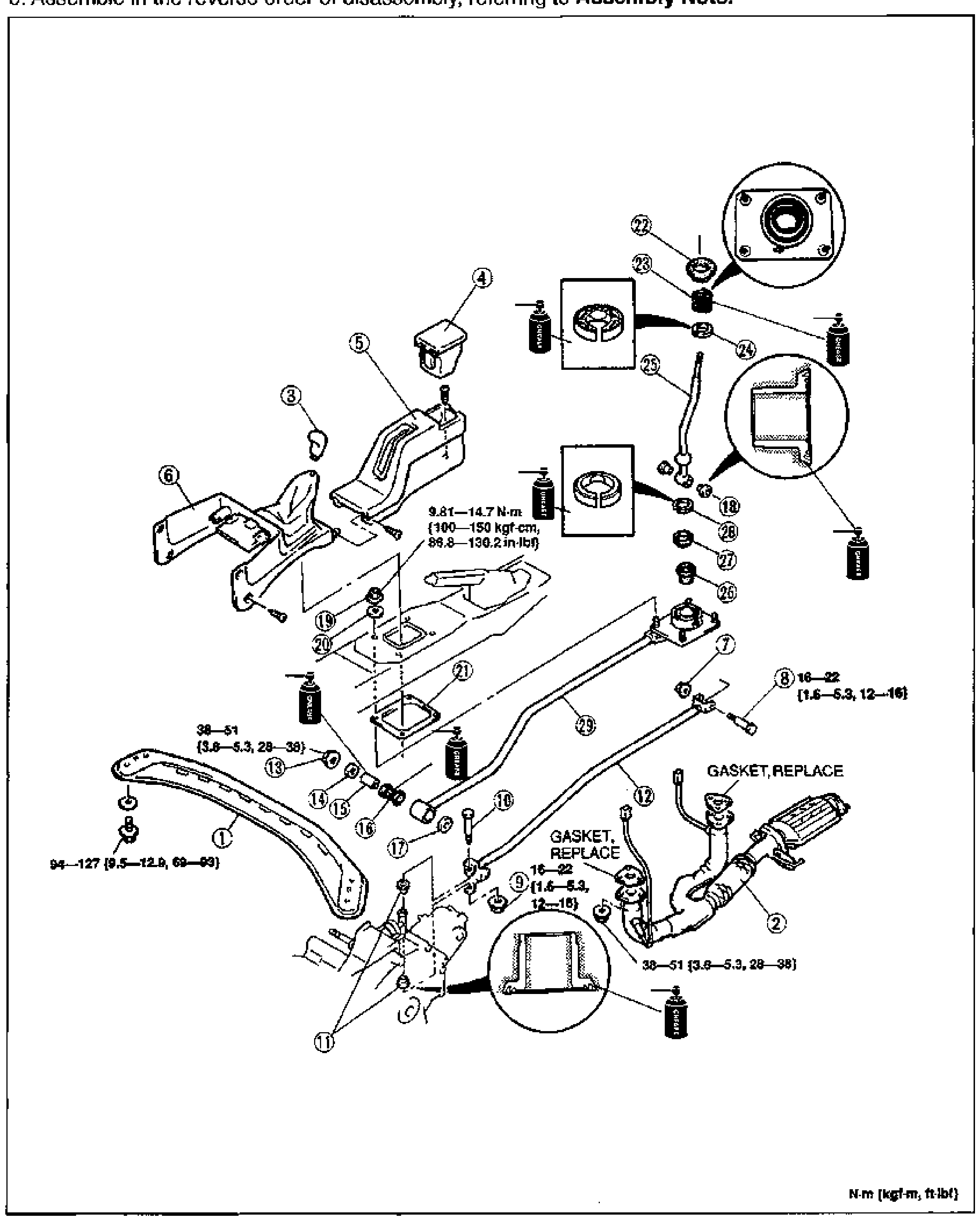
Shift Mechanism — Overhaul
J2-54Exploded view of the shift mechanism (manual transmission shift lever and change rod). Numbered balloons 1 through 29 identify components including the shift lever, knob, boot/console trim, change rod, joints, bushings, gaskets and mounting bolts. Grease application points and 'GASKET, REPLACE' notes are called out. Torque values are printed beside several fasteners. Two circular detail insets show joint/bushing cross-sections.

Shift Mechanism — Parts Legend / Assembly Note
J2-55Front and Rear Axles
M10 diagrams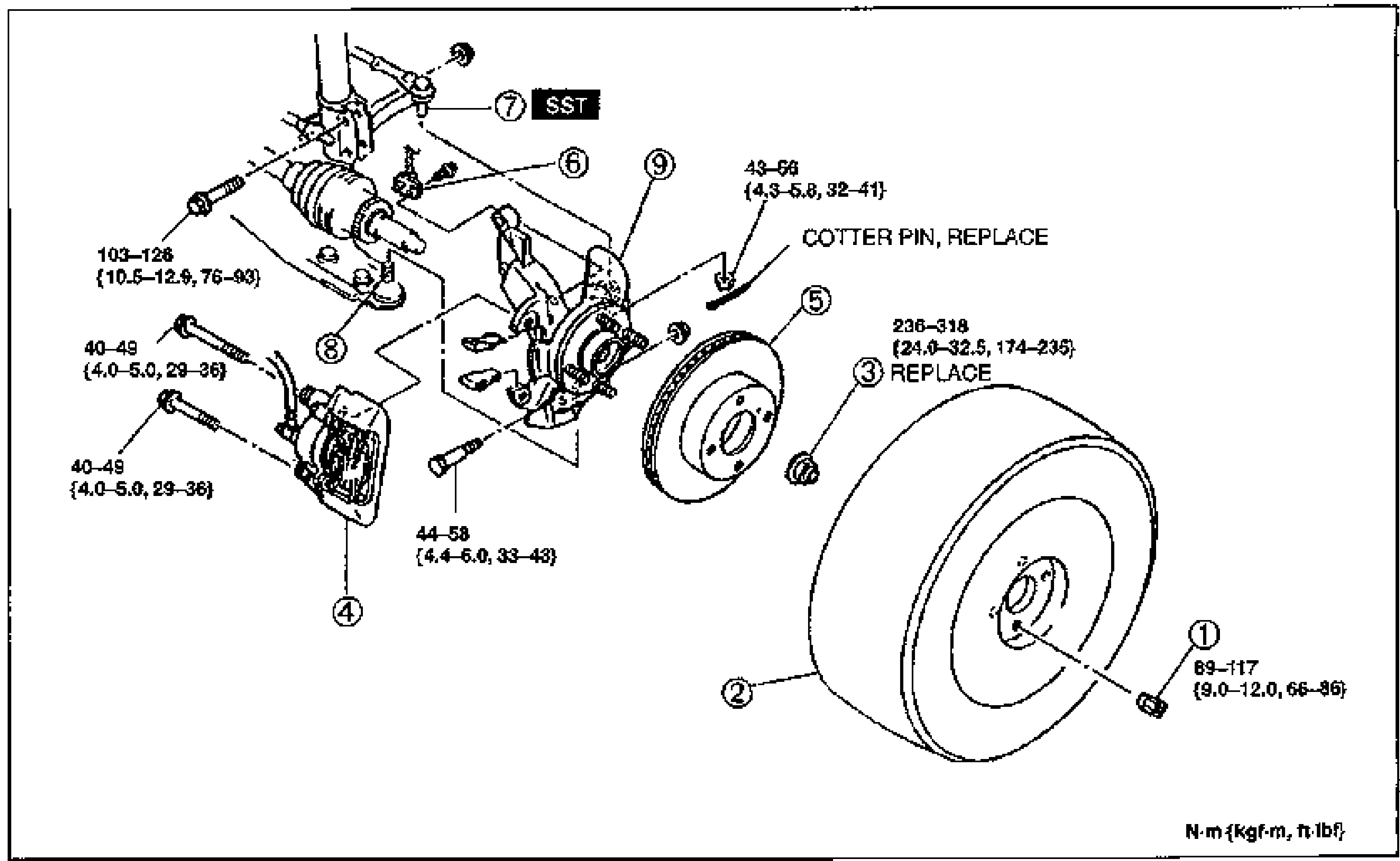
Front Axle — Removal / Installation
M-6Exploded view of the front axle / wheel hub and steering knuckle assembly. Numbered balloons 1-9 identify wheel nut, wheel and tire, locknut, brake caliper assembly, disc plate, ABS wheel-speed sensor, tie-rod end, lower ball joint, and knuckle/wheel hub/dust cover. Tightening torques are printed beside fasteners; 'SST' marks the tie-rod end tool, 'COTTER PIN, REPLACE' and 'REPLACE' notes are called out. Units footnote: N·m {kgf·m, ft·lbf}.
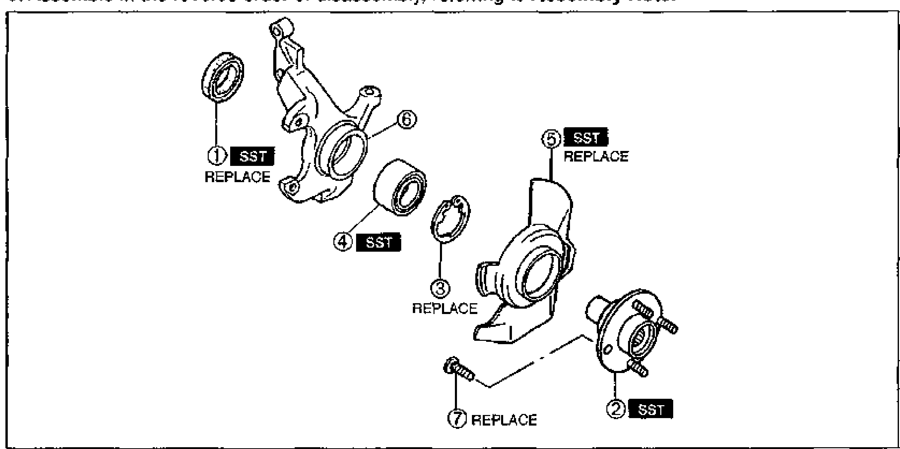
FRONT AXLE — Disassembly / Inspection / Assembly
M-8Exploded view of the front axle / steering knuckle and front wheel hub assembly. Numbered balloons: 1 Oil seal (SST, REPLACE), 2 Front wheel hub assembly (SST), 3 Retaining ring (REPLACE), 4 Wheel bearing (SST), 5 Dust cover (SST, REPLACE), 6 Knuckle, 7 Hub bolt (REPLACE). The knuckle, bearing, retaining ring, dust cover, hub and hub bolt are shown separated along their assembly axis.
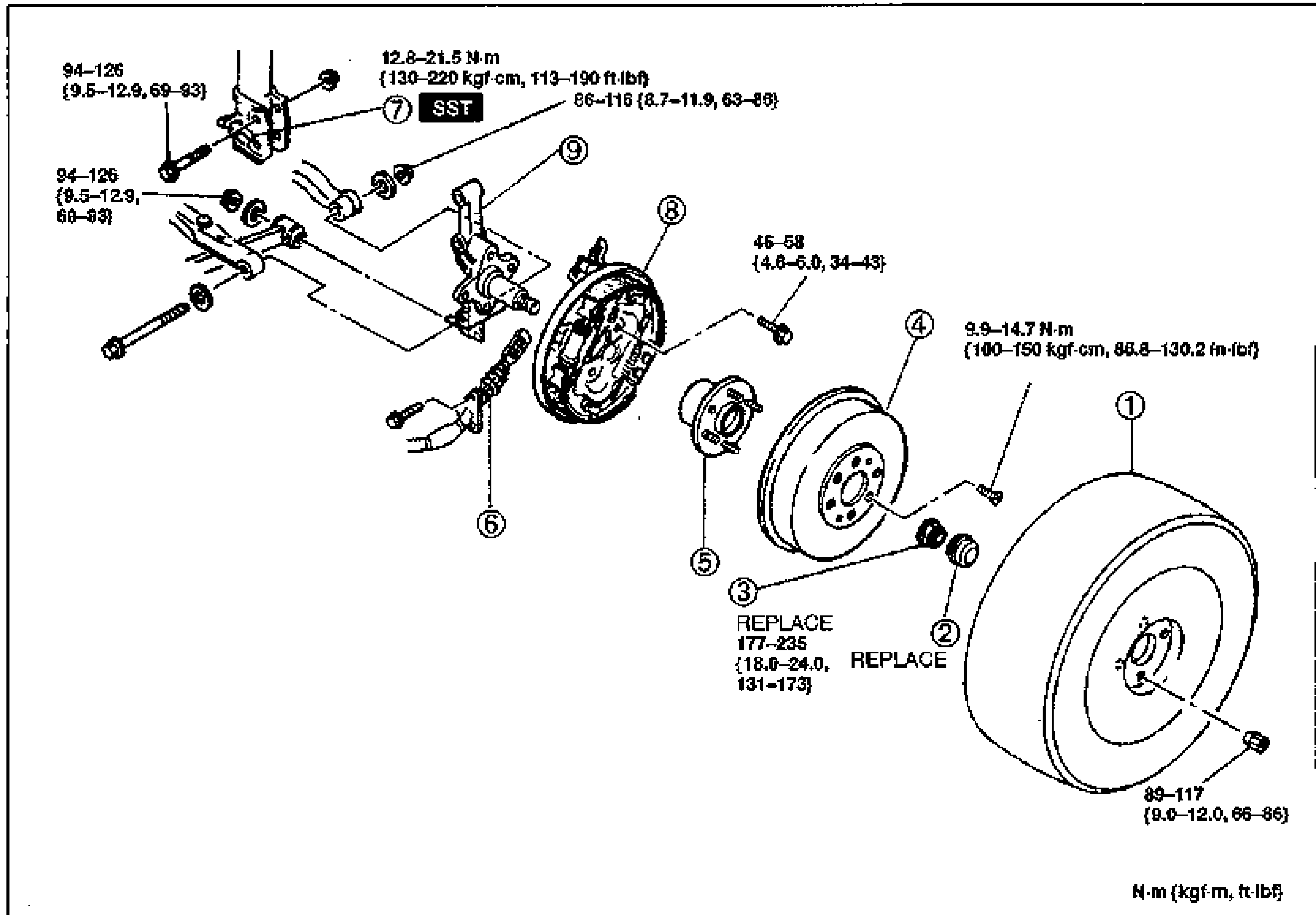
REAR AXLE — Removal / Inspection / Installation
M-12Exploded view of the rear axle / drum brake assembly with torque values (N·m {kgf·m, ft·lbf}). Numbered balloons: 1 Wheel and tire, 2 Hub cap (REPLACE), 3 Locknut (REPLACE), 4 Brake drum, 5 Hub bearing assembly, 6 Parking brake cable, 7 Brake pipe (SST), 8 Rear brake assembly, 9 Rear hub spindle. Torque callouts: 94-126 N·cm {9.5-12.9, 69-93} for the spindle/backing bolts, 12.8-21.5 N·m {130-220 kgf·cm, 113-190 in·lbf} and 86-116 {8.7-11.9, 63-86} near the brake pipe, 45-58 {4.6-6.0, 34-43} on the brake-assembly bolt, 9.9-14.7 N·m {100-150 kgf·cm, 86.8-130.2 in·lbf} on the drum screw, 177-235 {18.0-24.0, 131-173} on the locknut, 89-117 {9.0-12.0, 66-86} on the wheel/tire.
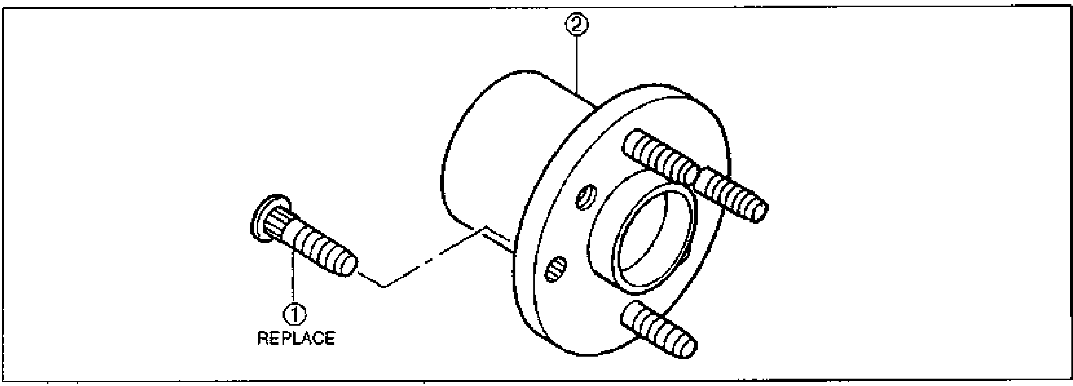
REAR AXLE — Removal/Installation Note (Brake pipe, Locknut) and Disassembly/Assembly
M-13Exploded view of the rear hub bearing assembly. Balloon 1 Hub bolt (REPLACE) shown separated to the lower-left; balloon 2 Hub bearing assembly is the integral hub/bearing unit with wheel studs.
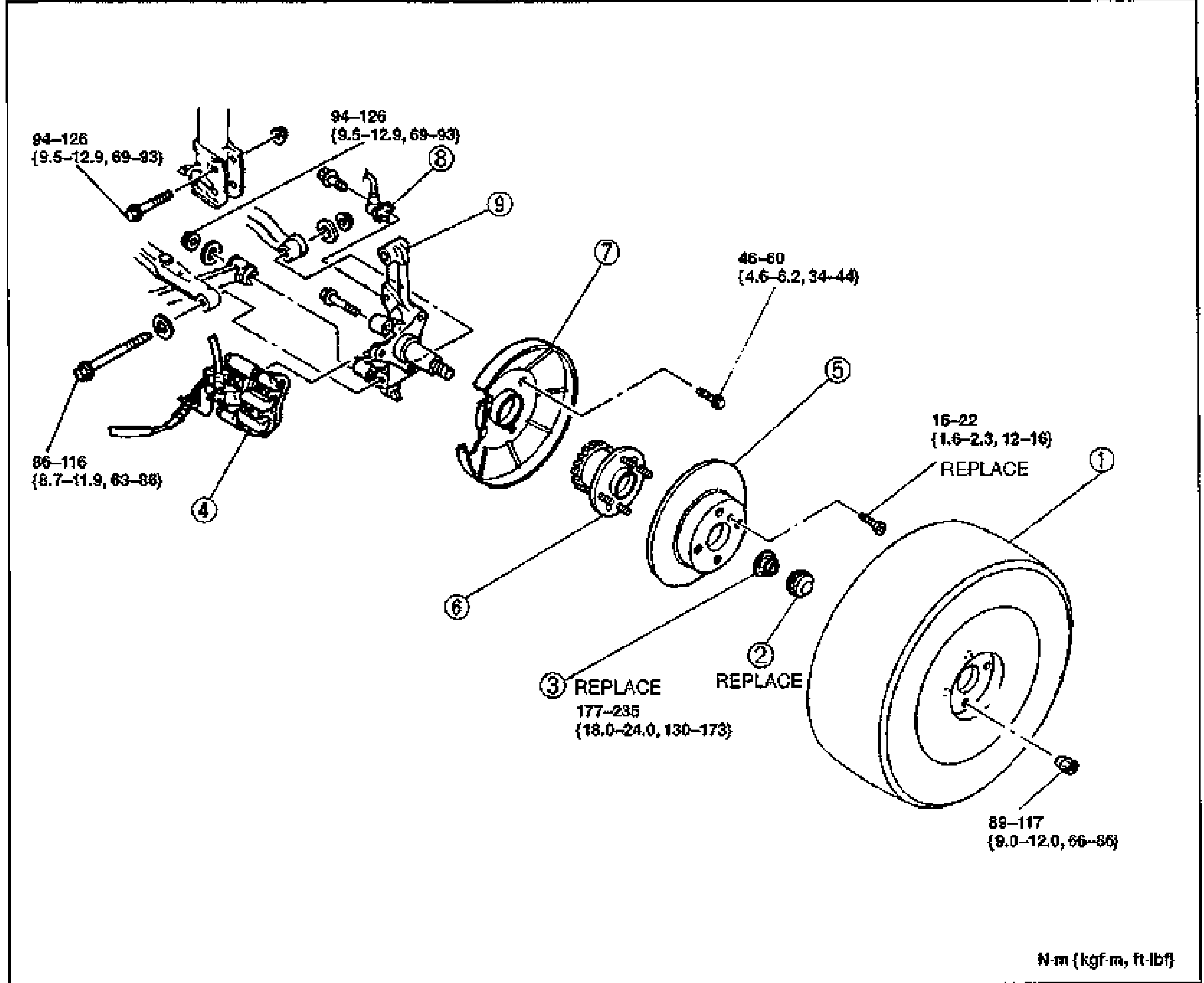
REAR AXLE (Disc brake) — Removal / Inspection / Installation
M-15Exploded view of the rear disc-brake axle assembly with torque values (N·m {kgf·m, ft·lbf}). Numbered balloons: 1 Wheel and tire, 2 Hub cap (REPLACE), 3 Locknut (REPLACE), 4 Brake caliper assembly, 5 Disc plate, 6 Hub bearing assembly, 7 Dust cover, 8 ABS wheel-speed sensor, 9 Rear hub spindle. Torque callouts: 94-126 N·cm {9.5-12.9, 69-93} on caliper bracket and ABS sensor bolts, 86-116 {8.7-11.9, 63-86} on the lower caliper bolt, 46-60 {4.6-6.2, 34-44} on the dust cover bolt, 16-22 {1.6-2.3, 12-16} on the disc plate screw, 177-235 {18.0-24.0, 130-173} on the locknut, 89-117 {9.0-12.0, 66-86} on the wheel/tire.
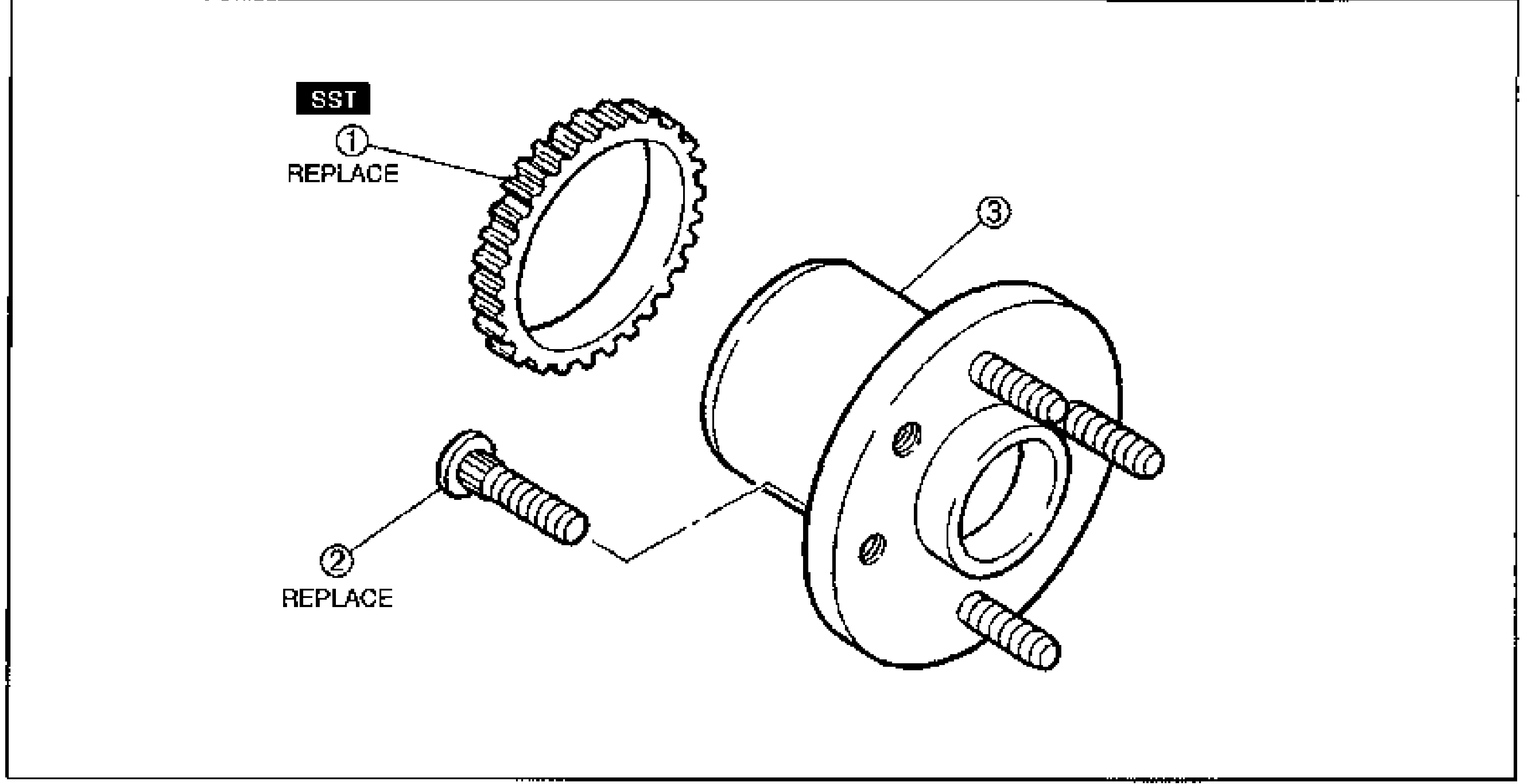
REAR AXLE (Disc brake) — Locknut Removal/Installation Note; Disassembly / Assembly
M-16Exploded view of the rear hub bearing assembly. Balloon 1 ABS sensor rotor (toothed ring, SST, REPLACE) at upper-left, balloon 2 Hub bolt (REPLACE) lower-left, balloon 3 Hub bearing assembly (integral hub with wheel studs) at right.
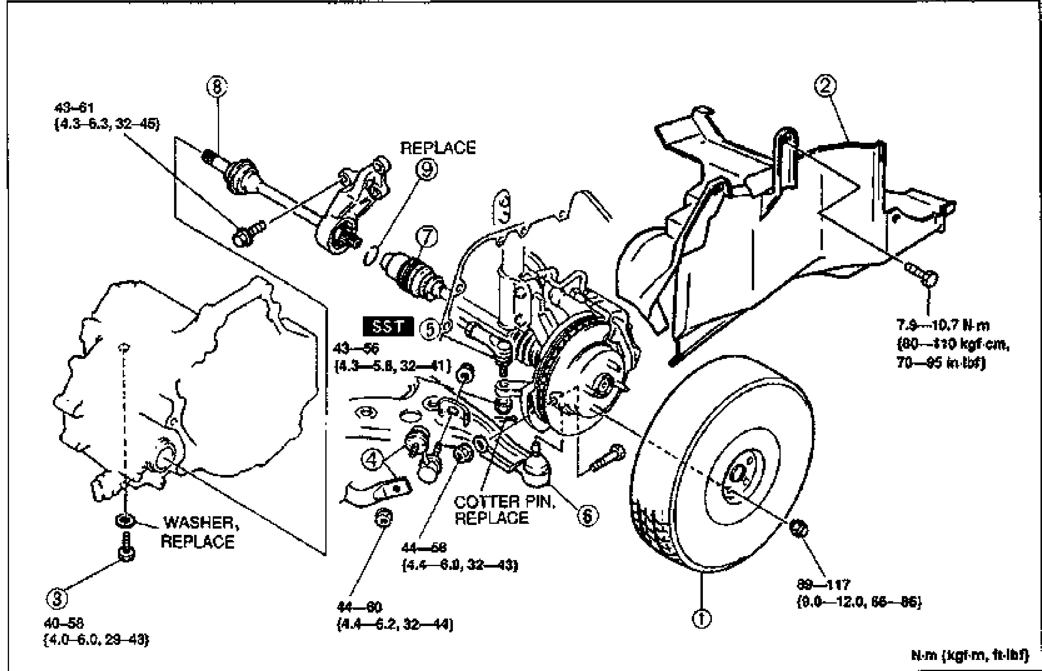
DRIVE SHAFT
M-19Exploded view of the drive shaft / joint shaft removal-installation with numbered balloon callouts 1-9 and tightening torque annotations. Shows wheel and tire (1), splash shield (2), drain plug (3) with WASHER REPLACE, stabilizer control link (4), tie-rod end (5) installed with SST, lower ball joint (6) with COTTER PIN REPLACE, right drive shaft and axle (7) marked REPLACE, joint shaft (8), and clip (9). Torque values are shown in N·m {kgf·m, ft·lbf}.
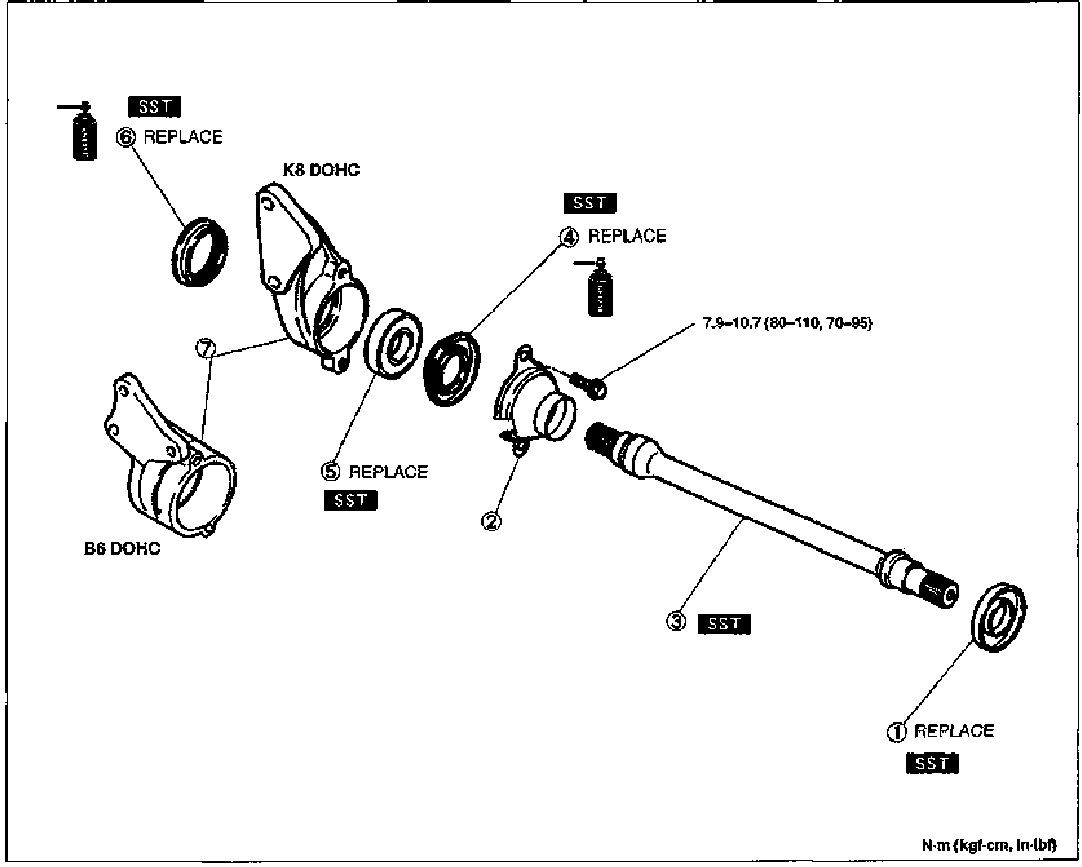
DRIVE SHAFT
M-22Exploded view of the joint shaft disassembly/inspection/assembly with numbered balloon callouts 1-7. Shows the dust cover differential side for K8 DOHC and B6 DOHC variants, dust seals, bearing, joint shaft, and bracket. Several parts are marked REPLACE and SST. A bolt torque of 7.9-10.7 N·m {80-110 kgf·cm, 70-95 in·lbf} is annotated. Units: N·m {kgf·cm, in·lbf}.
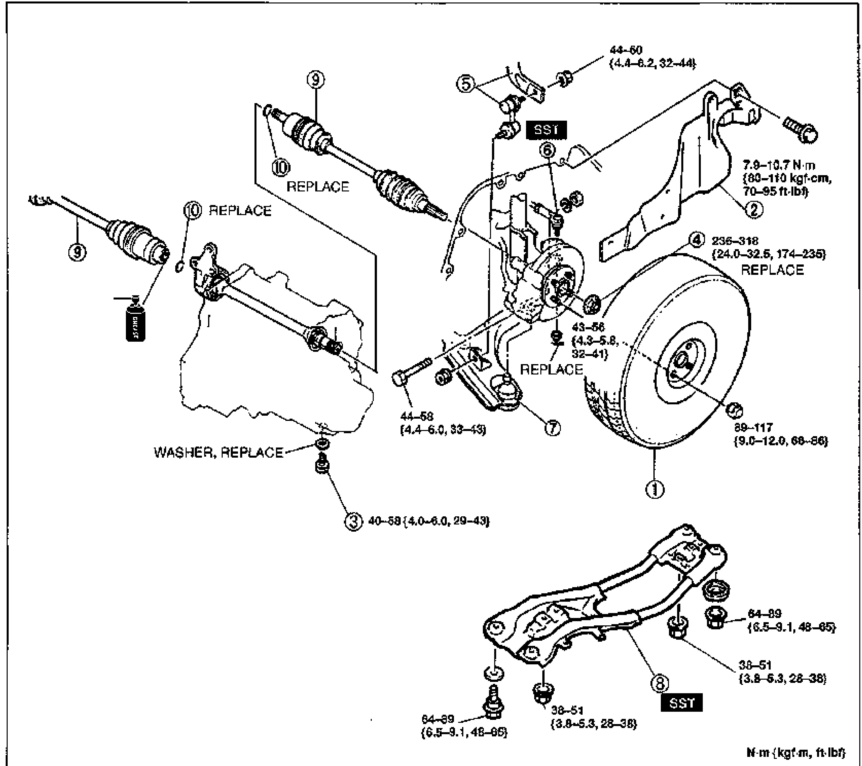
DRIVE SHAFT (TRIPOD JOINT)
M-25Exploded view of the drive shaft (tripod joint) removal-installation with numbered balloon callouts 1-10 and tightening torque annotations. Shows wheel and tire (1), splash shield (2), drain plug (3) with WASHER REPLACE, locknut (4) REPLACE, stabilizer control link (5), tie-rod end (6) installed with SST, lower ball joint (7), engine mount member (8) with SST, drive shaft (9) REPLACE, and clip (10) REPLACE. Torque values are in N·m {kgf·m, ft·lbf}.
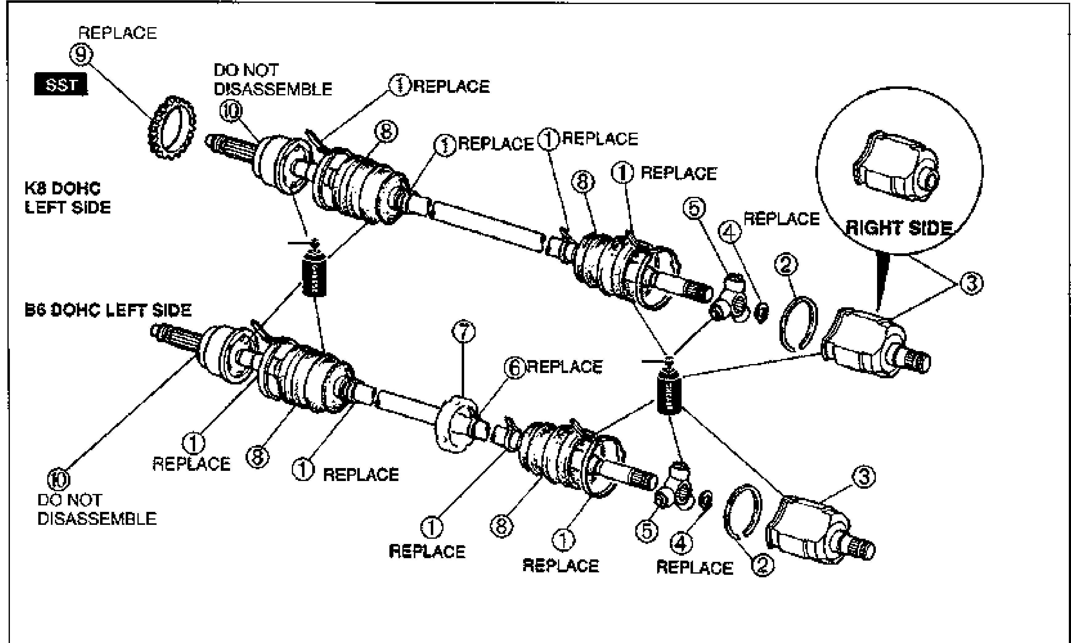
DRIVE SHAFT
M-29Exploded view of the drive shaft assembly showing K8 DOHC left side (top), B6 DOHC left side (bottom), and a right-side detail in a circular callout. Numbered balloon callouts 1–10 identify components: boot band, stopper ring, outer ring, snap ring, tripod joint, band, dynamic damper, boot, ABS sensor rotor, and shaft and ball joint assembly. Several parts are labeled REPLACE, two are labeled DO NOT DISASSEMBLE, and the ABS sensor rotor (9) is marked SST.
Steering System
N11 diagrams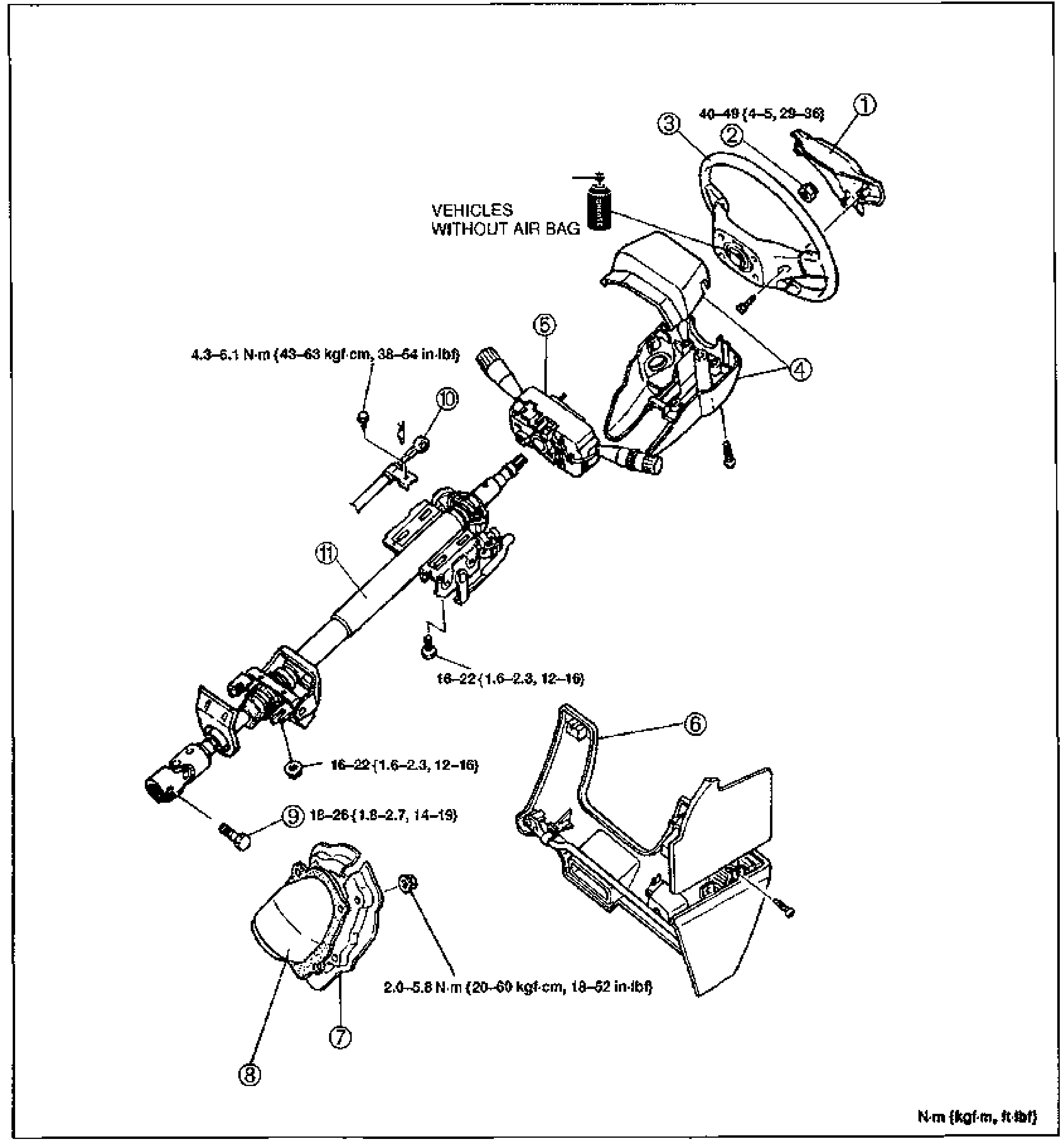
Steering Wheel and Column — Removal/Installation
N-13Exploded view of the steering wheel and steering column assembly. From upper right: horn cap / air bag module (1), locknut (2), steering wheel (3), column cover (4), combination switch (5), lower panel (6), set plate (7), dust cover (8), fixing bolt (9), interlock cable (10, ATX only), and steering shaft assembly (11). Tightening-torque callouts shown: 40—49 {4—5, 29—36} at the steering wheel locknut, 4.3—6.1 N·m {43—63 kgf·cm, 38—54 in·lbf}, 16—22 {1.6—2.3, 12—16} (two locations), 18—26 {1.8—2.7, 14—19}, and 2.0—5.8 N·m {20—60 kgf·cm, 18—52 in·lbf}. A note marks 'VEHICLES WITHOUT AIR BAG' for the horn cap area.
Steering Wheel — Removal/Installation Notes; Steering Shaft Disassembly/Inspection/Assembly
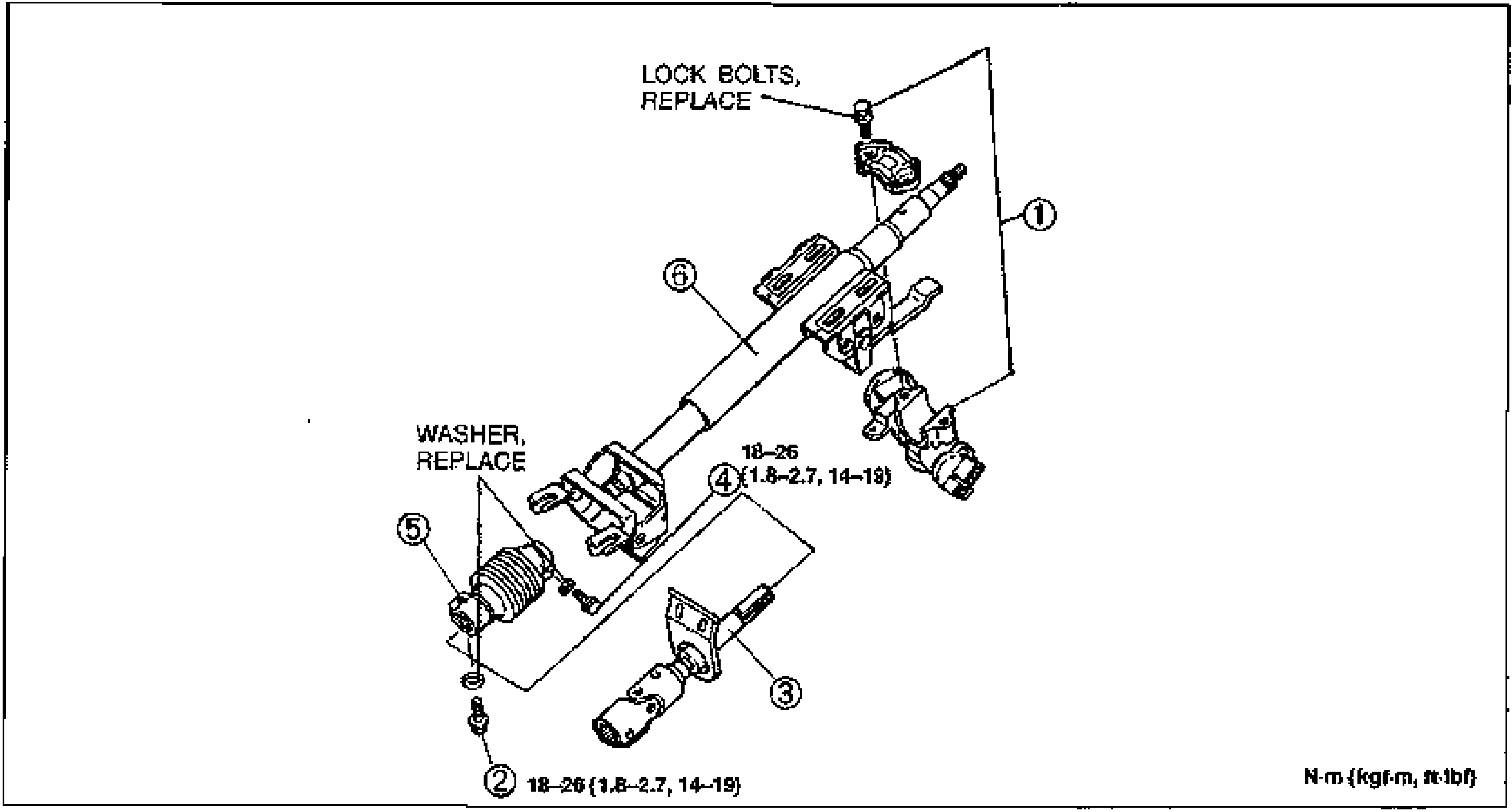
N-14Exploded view of the steering shaft assembly for disassembly/assembly. Components: steering lock assembly (1) at top secured by lock bolts marked 'LOCK BOLTS, REPLACE', fixing bolt for universal joint/intermediate shaft (2), intermediate shaft (3), fixing bolt for steering shaft/universal joint (4) with a washer marked 'WASHER, REPLACE', universal joint (5), and energy absorbing shaft assembly (6). Torque callouts 18—26 {1.8—2.7, 14—19} appear at items 2 and 4.
ENGINE SPEED SENSING POWER STEERING — Boot Removal / Installation
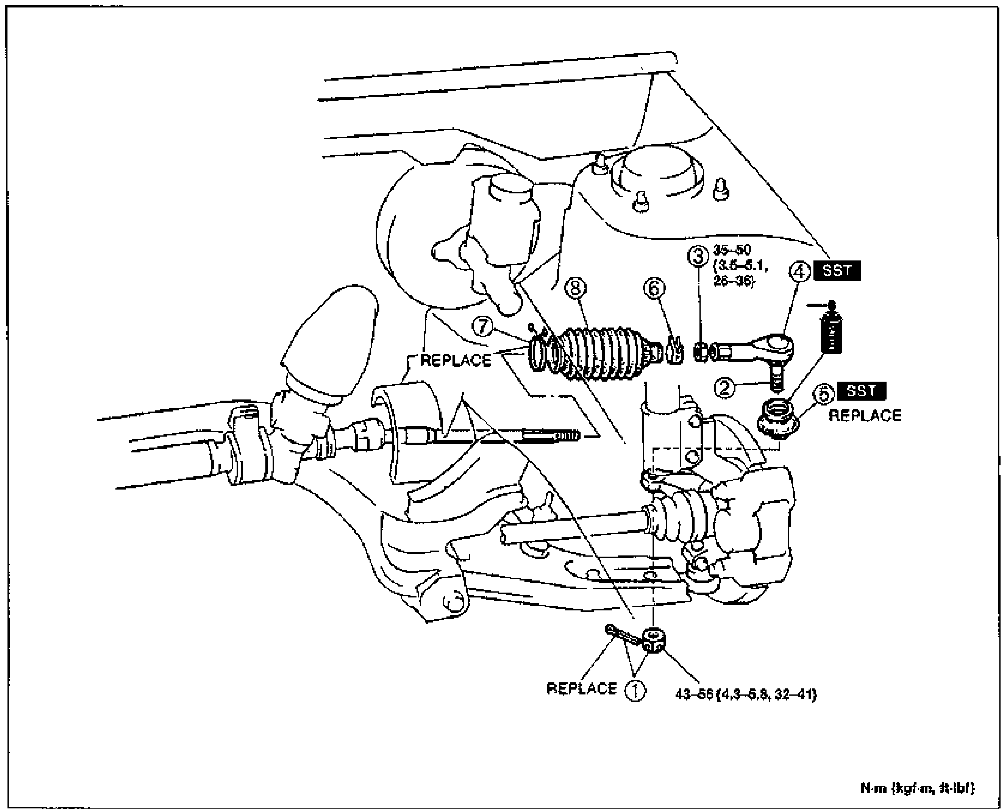
N-17Exploded view of the front suspension / steering tie-rod and boot assembly. Numbered balloon callouts (1-8) identify the cotter pin & nut, tie-rod end ball joint, locknut, tie-rod end, tie-rod end boot, boot band, boot wire, and rack boot. Tightening torque annotations appear at callout 3 (35-50 N·m {3.6-5.1 m-kgf, 26-36 ft-lbf}) and at callout 1 (43-58 N·m {4.3-5.9 m-kgf, 32-41 ft-lbf}). 'SST' tool boxes are shown at callouts 4 and 5. 'REPLACE' labels mark the cotter pin (1), rack boot (7) and tie-rod end boot (5). Units note: N·m {kgf·m, ft-lbf}.
ENGINE SPEED SENSING POWER STEERING — Steering Gear and Linkage (B6 DOHC) Removal / Installation
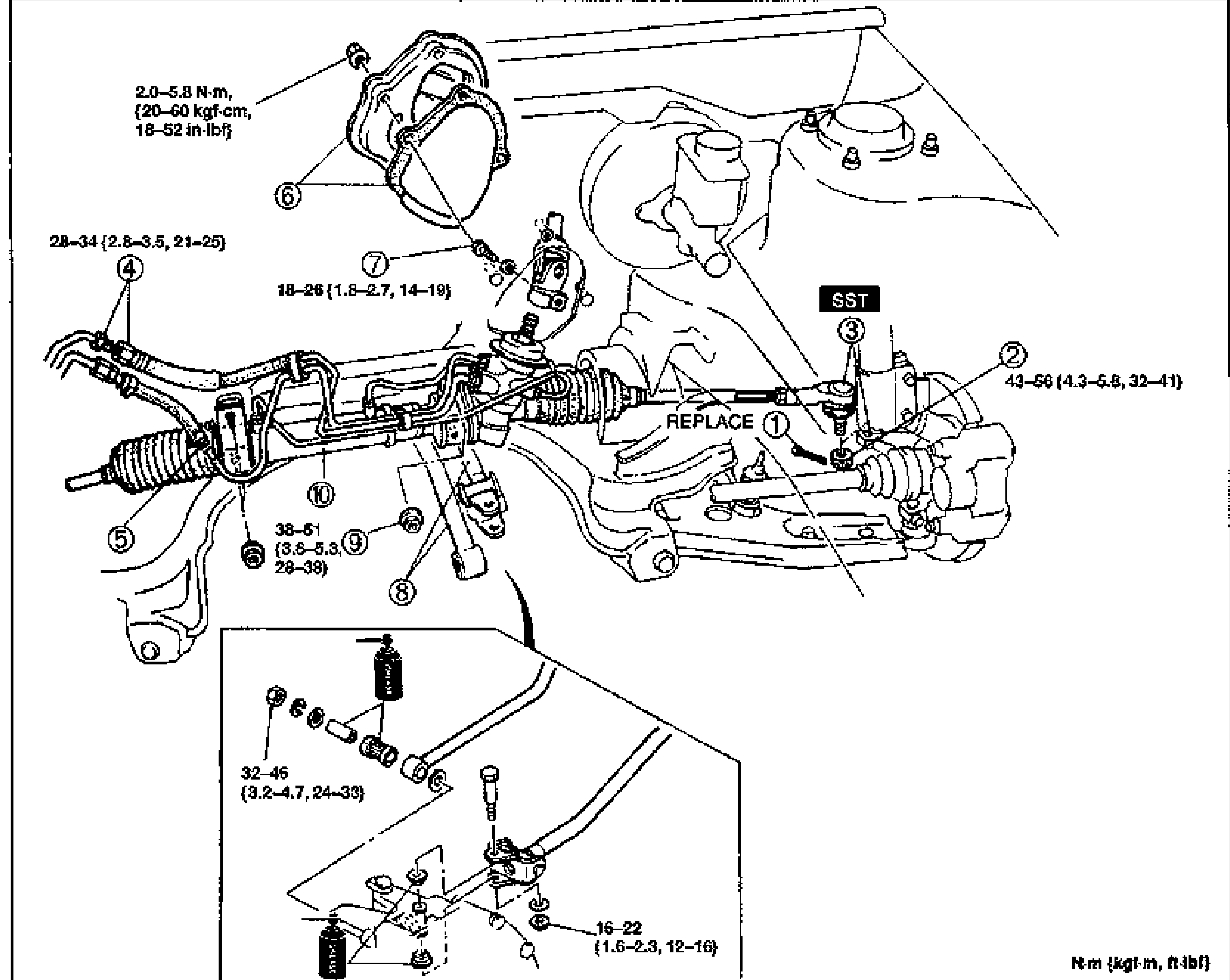
N-19Exploded view of the steering gear and linkage for the B6 DOHC engine, showing the rack-and-pinion gear, pressure pipe, return hose, set plate and dust cover, tie-rod ends, intermediate/pinion shaft and crossmember mounting. Numbered balloon callouts 1-10 with several tightening torque annotations. An inset (lower left) detail shows the intermediate shaft / pinion shaft fixing area with additional fasteners. 'SST' tool box appears near callout 3, and 'REPLACE' labels the cotter pin (1). Units note: N·m {kgf·m, ft-lbf}.
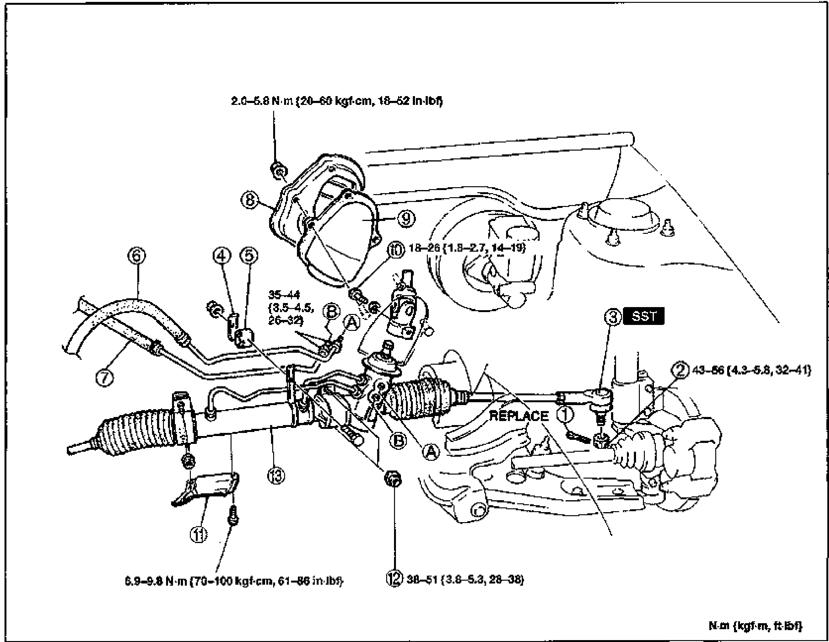
ENGINE SPEED SENSING POWER STEERING — Steering Gear and Linkage (K8 DOHC) Removal / Installation
N-20Exploded view of the steering gear and linkage for the K8 DOHC engine, showing the rack-and-pinion gear, pressure pipe, return pipe, support bracket, tube rubber, set plate, dust cover, insulator, tie-rod end and crossmember mounting. Numbered balloon callouts 1-13 with section markers A and B, plus several tightening torque annotations. 'SST' tool box appears near callout 3, and 'REPLACE' labels the cotter pin (1). Units note: N·m {kgf·m, ft-lbf}.
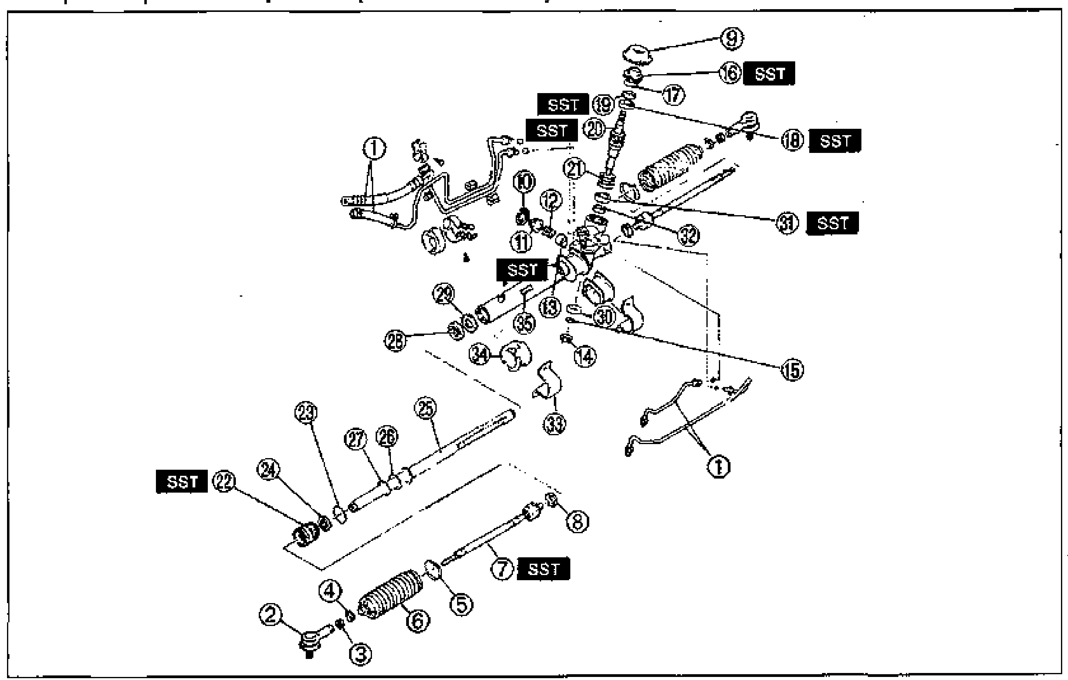
ENGINE SPEED SENSING POWER STEERING — Steering Gear Disassembly / Inspection (B6 DOHC)
N-22Large exploded view of the rack-and-pinion steering gear for the B6 DOHC engine, showing all internal components: oil pipe, tie-rod ends, locknuts, boot assembly, tie rod, dust cover, washer, adjustment cover, spring, support yoke, housing cover, plug, O-rings, oil seals, bearings, pinion shaft assembly, seal rings, outer box, U-gasket, steering rack, inner guide, mounting bracket/rubber, and gear housing. Numbered balloon callouts 1-35. Multiple 'SST' tool boxes are shown at various special-tool locations (near callouts 7, 16, 18, 19, 20, 22, 31, and the support yoke area).
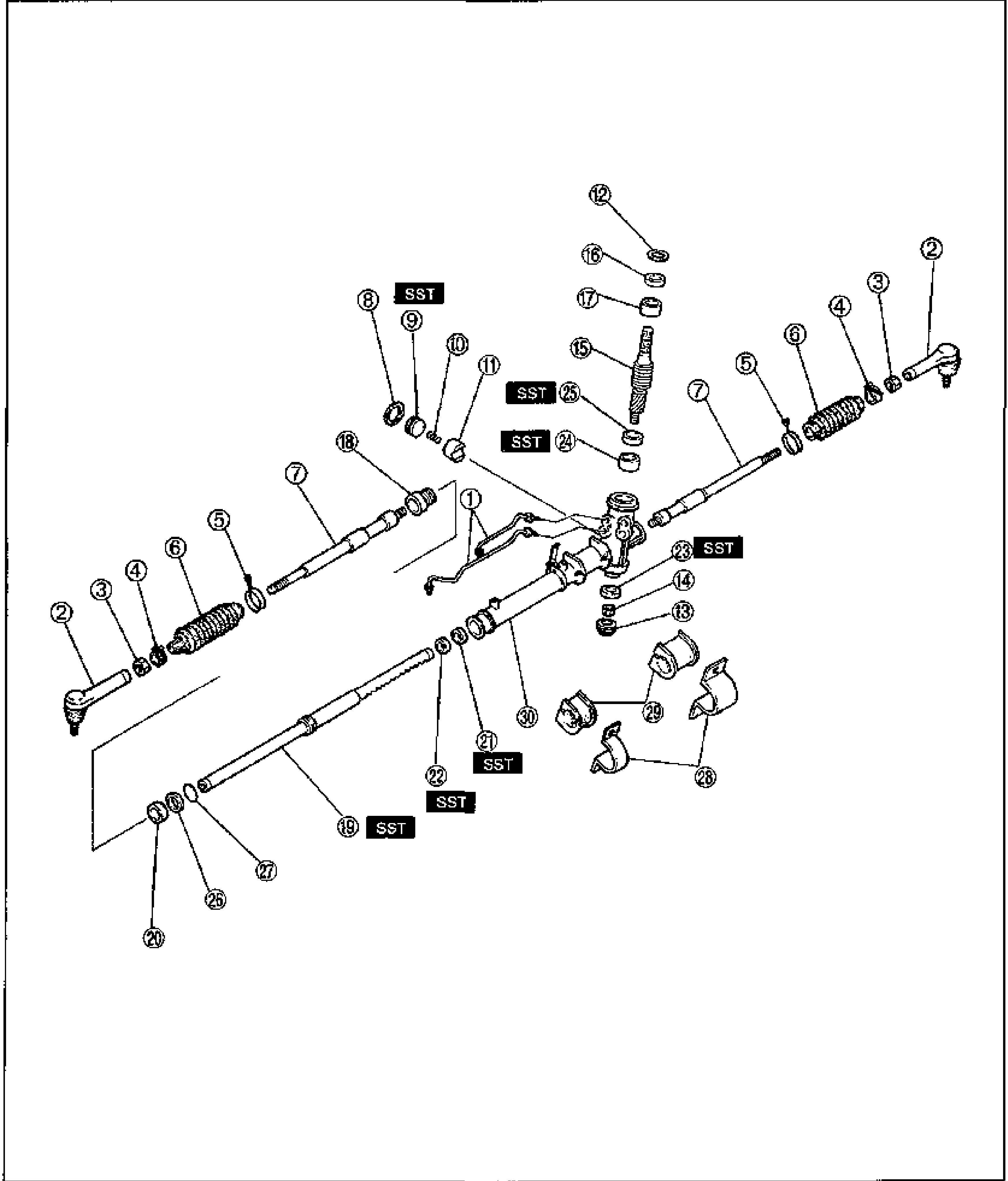
ENGINE SPEED SENSING POWER STEERING — Disassembly / Inspection (K8 DOHC)
N-30Exploded view of the K8 DOHC engine-speed-sensing power steering gear assembly. Numbered balloons 1 through 30 identify components from the tie-rod ends and boots through the steering rack, pinion/valve assembly, mounting brackets and rubbers. Several positions are marked SST, indicating a special service tool is required at that step. Components shown include tie-rod ends, boots/boot bands, the rack, oil seals, bearings, the pinion shaft assembly with seal ring, mounting brackets and rubber bushings.
ENGINE SPEED SENSING POWER STEERING - POWER STEERING OIL PUMP (B6 DOHC)
N-43Exploded view of the B6 DOHC power steering oil pump removal/installation. Shows the P/S oil pump assembly with pulley, bracket, mounting bolts and nuts, adjusting bolt, P/S drive belt, pressure hose, return hose, and O-rings. Numbered balloon callouts 1-12 with tightening torques. Torque units: N·m (kgf·m, ft-lbf).
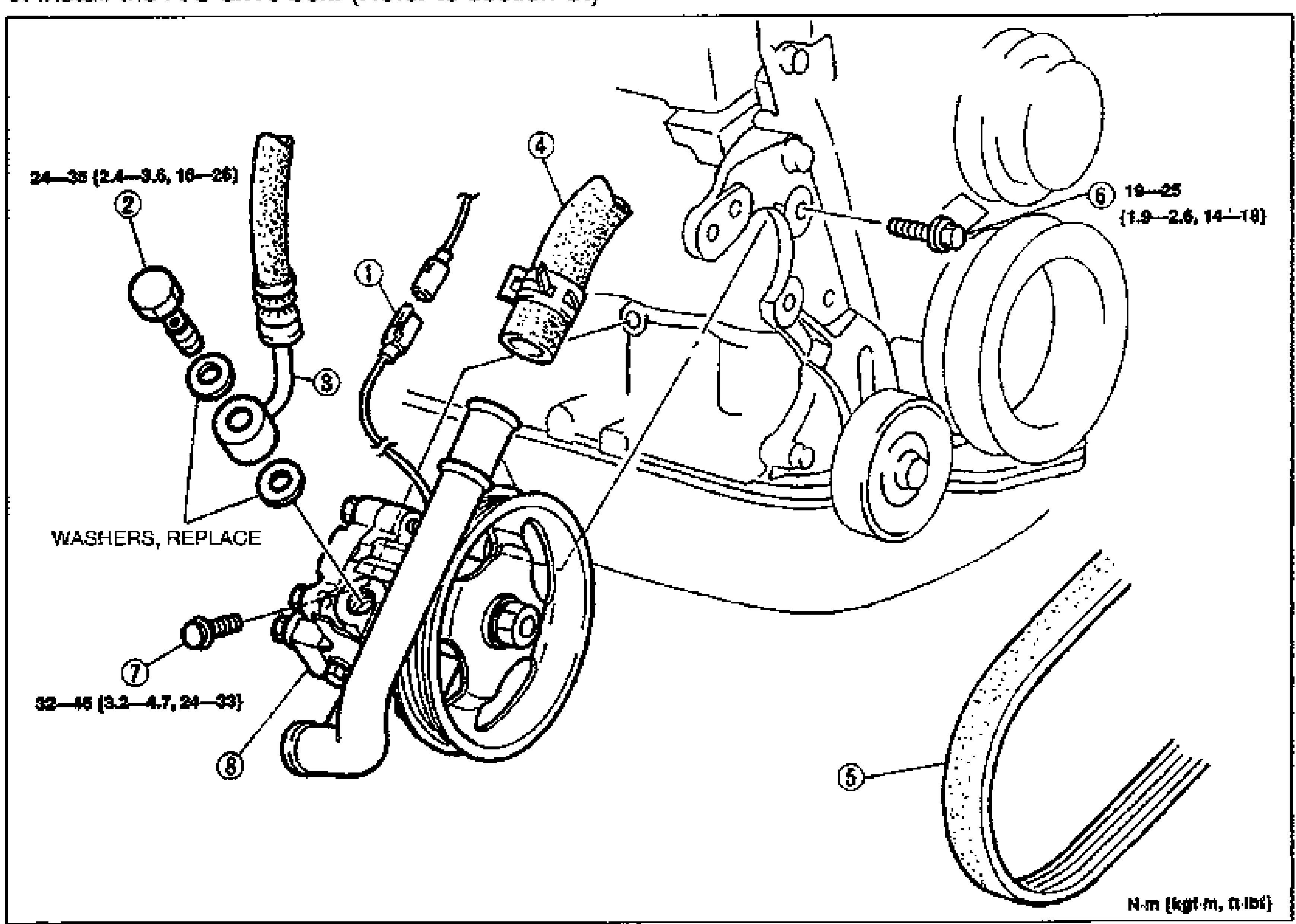
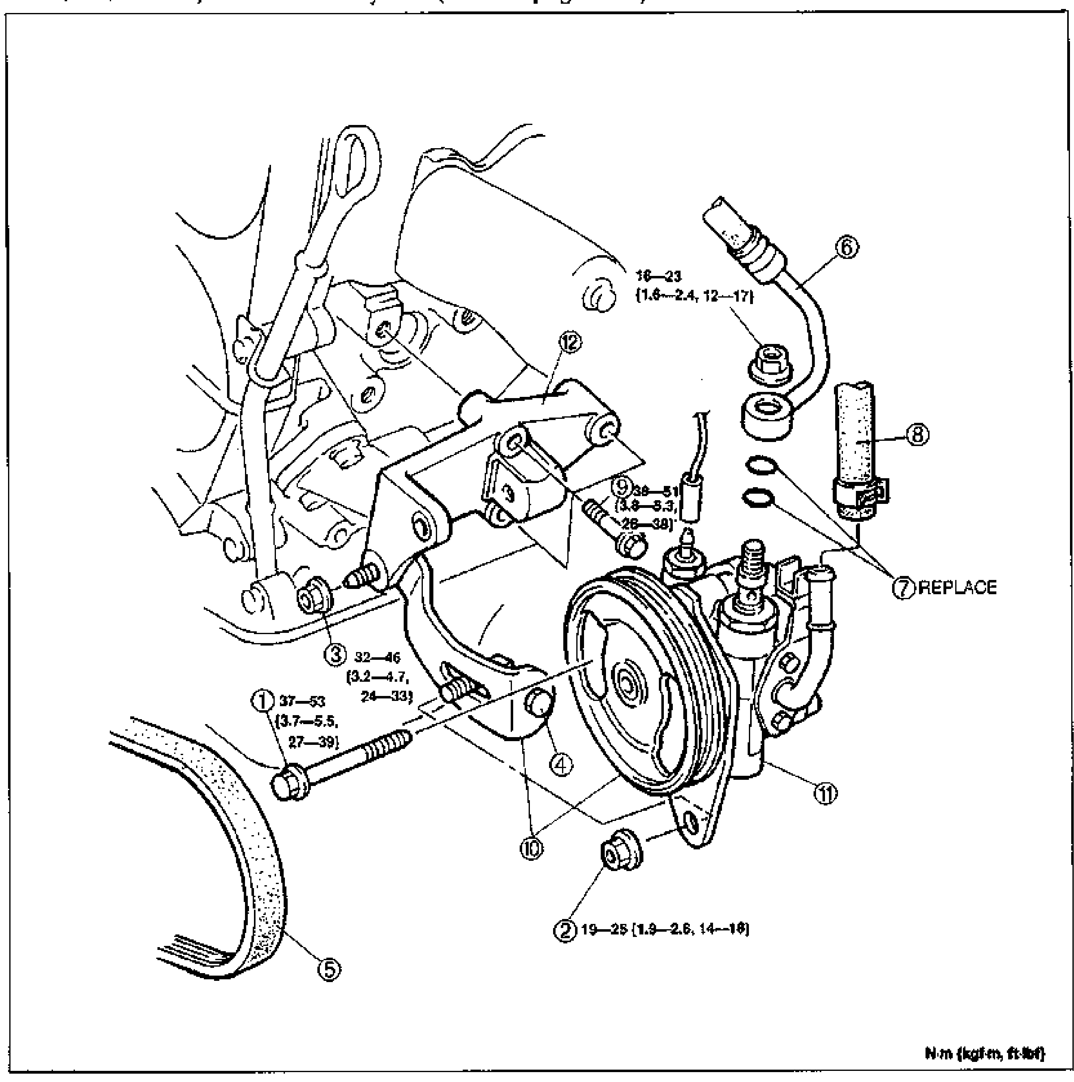
ENGINE SPEED SENSING POWER STEERING - POWER STEERING OIL PUMP (K8 DOHC)
N-44Exploded view of the K8 DOHC power steering oil pump removal/installation. Shows the P/S oil pump assembly with pulley, pressure hose, return hose, P/S pressure switch connector, mounting bolts, washers, and P/S drive belt. Numbered balloon callouts 1-8 with tightening torques. Torque units: N·m (kgf·m, ft-lbf).
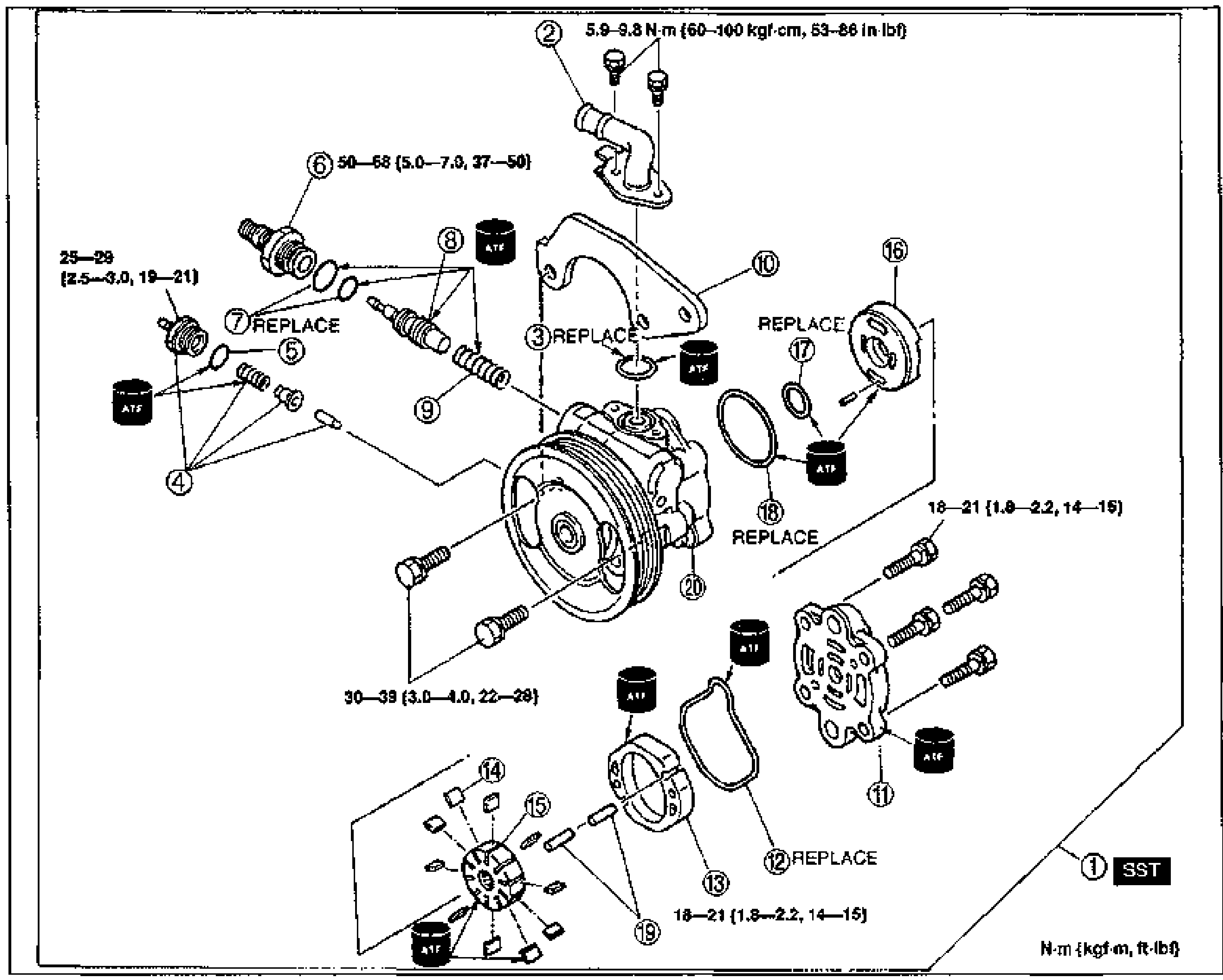
Engine Speed Sensing Power Steering — Oil Pump Disassembly / Inspection / Assembly (B6 DOHC)
N-45Exploded view of the engine speed sensing power steering oil pump (B6 DOHC). Shows 20 numbered balloon callouts for the disassembly/assembly sequence: oil pump body, suction pipe, O-rings, pressure-switch assembly, connector, control valve, spring, bracket, side plate, vane, rotor, cam ring, pin, and pump body front/rear. Tightening torque tags are printed beside fasteners, several parts are marked REPLACE, ATF-application symbols appear at multiple seal points, and item 1 (oil pump assembly) is tagged SST in the lower-right corner. Torque units note: N·m (kgf·m, ft-lbf).
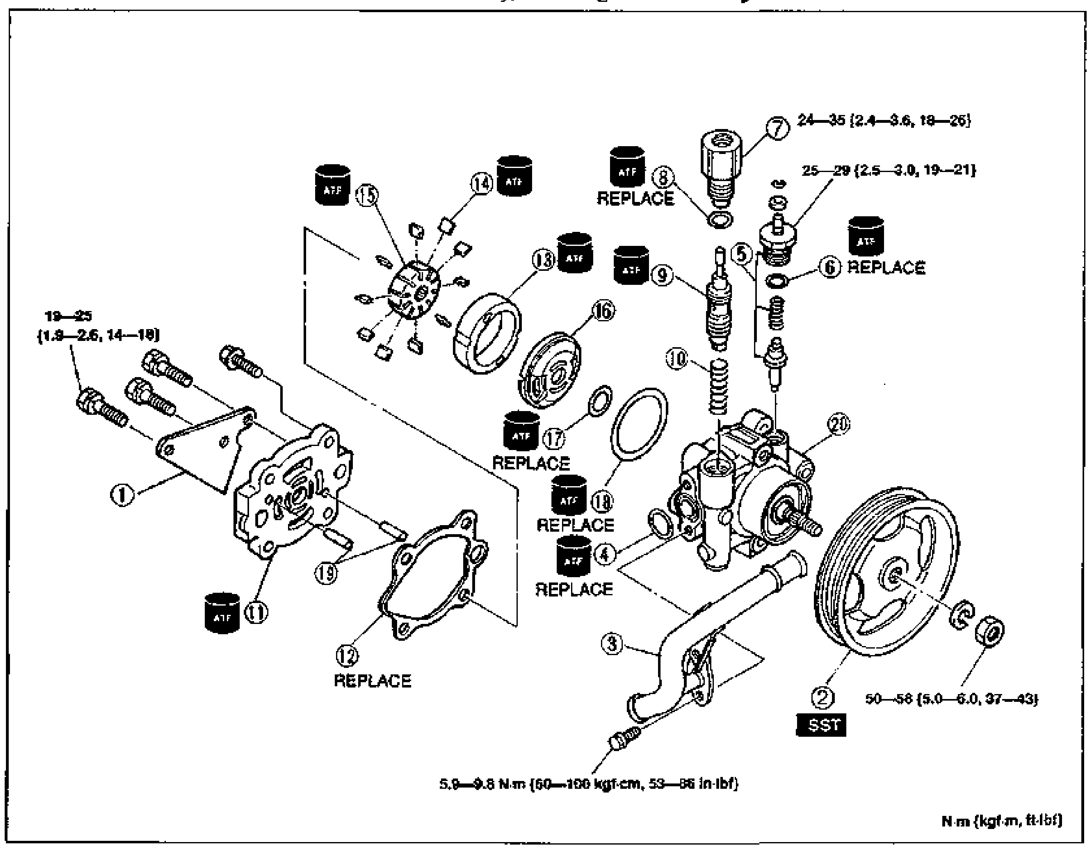
Engine Speed Sensing Power Steering — Oil Pump Disassembly / Inspection / Assembly (K8 DOHC)
N-48Exploded view of the engine speed sensing power steering oil pump (K8 DOHC). 20 numbered balloon callouts cover the disassembly/assembly sequence: bracket, pulley (SST), suction pipe, O-rings, pressure-switch assembly, connector, control valve, spring, pump body rear, seal washer, cam ring, vane, rotor, side plate, pins, and pump body front. Torque tags are printed at fasteners, several O-rings/seal washer are marked REPLACE, ATF-application symbols mark seal points, item 2 (pulley) is tagged SST. Torque units note: N·m (kgf·m, ft-lbf).
Braking System
P27 diagrams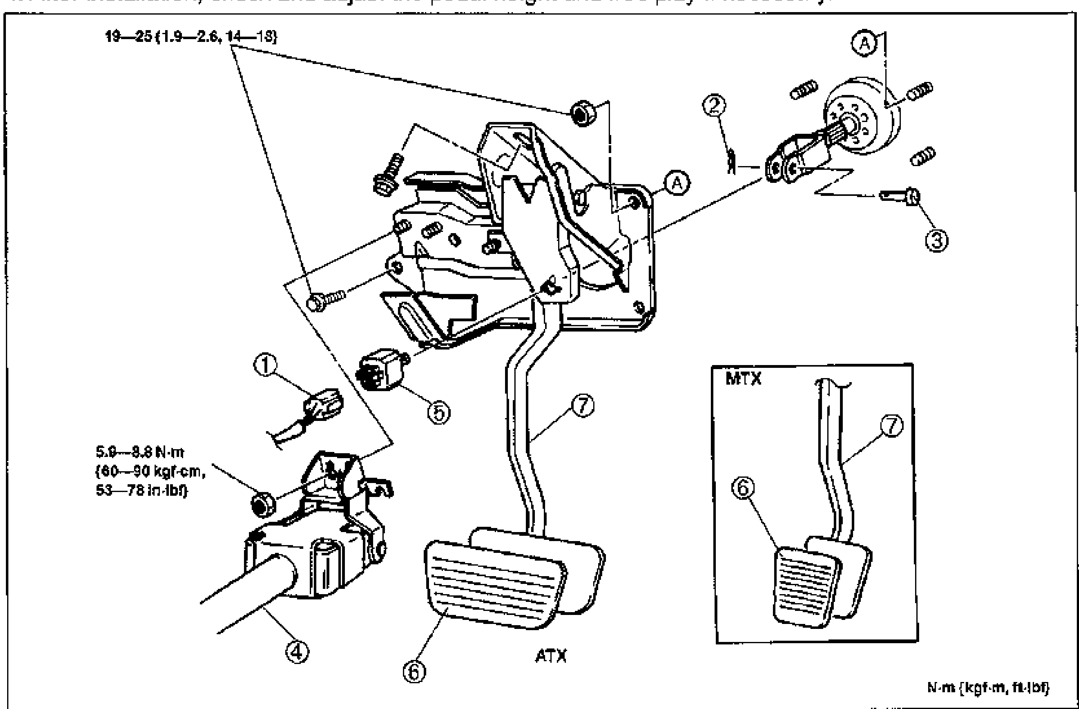
CONVENTIONAL BRAKE SYSTEM - Brake Pedal Removal / Inspection / Installation
P-11Exploded view of the brake pedal assembly. Shows the brake pedal, brake switch and connector, snap pin, clevis pin, steering shaft, and pad. Numbered balloon callouts 1-7 with tightening torques. An MTX inset (top-right box) shows the manual-transmission pedal pad variant vs the ATX (automatic) layout. Torque units: N·m (kgf·m, ft-lbf).
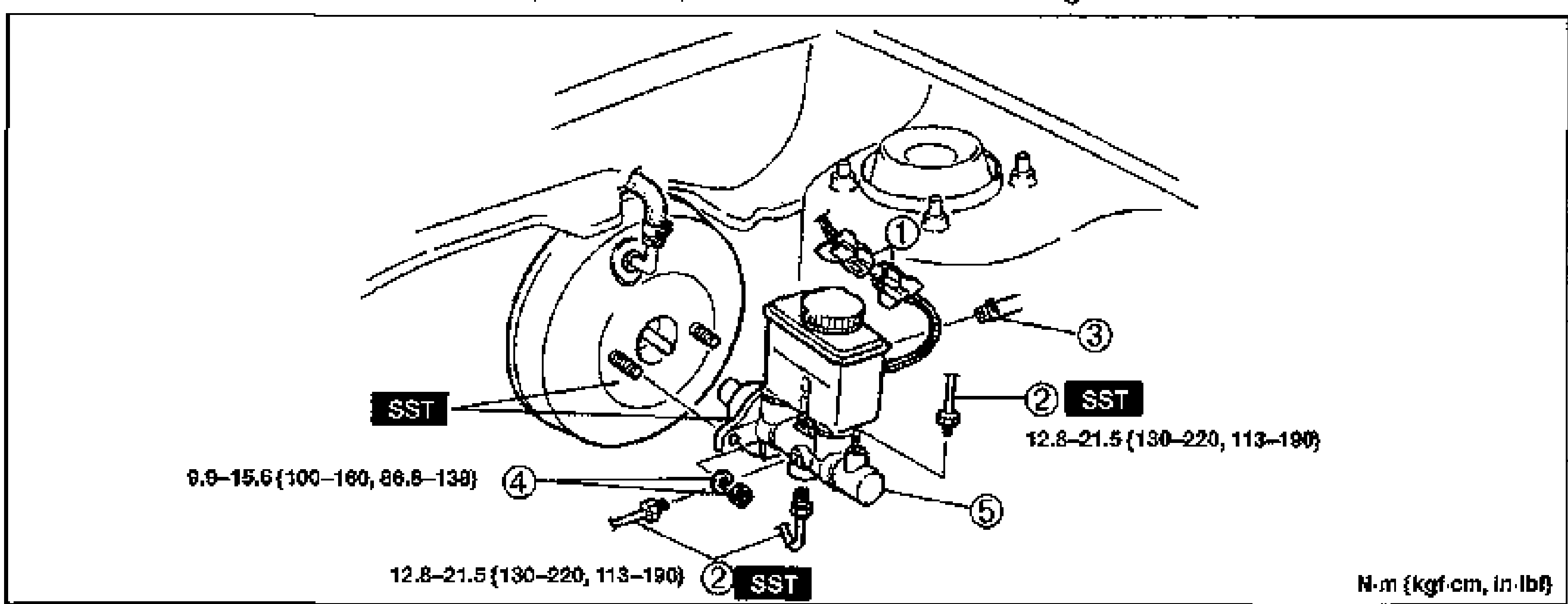
CONVENTIONAL BRAKE SYSTEM - MASTER CYLINDER (B6 DOHC)
P-12Exploded view of the B6 DOHC master cylinder removal/installation (NON ABS). Shows the master cylinder mounted to the power brake unit with fluid reservoir, fluid level sensor, brake pipes, hose (MTX), nut and washer. SST tools marked at brake pipe and mounting nut locations. Numbered balloon callouts 1-5 with tightening torques. Torque units: N·m (kgf-cm, in-lbf).
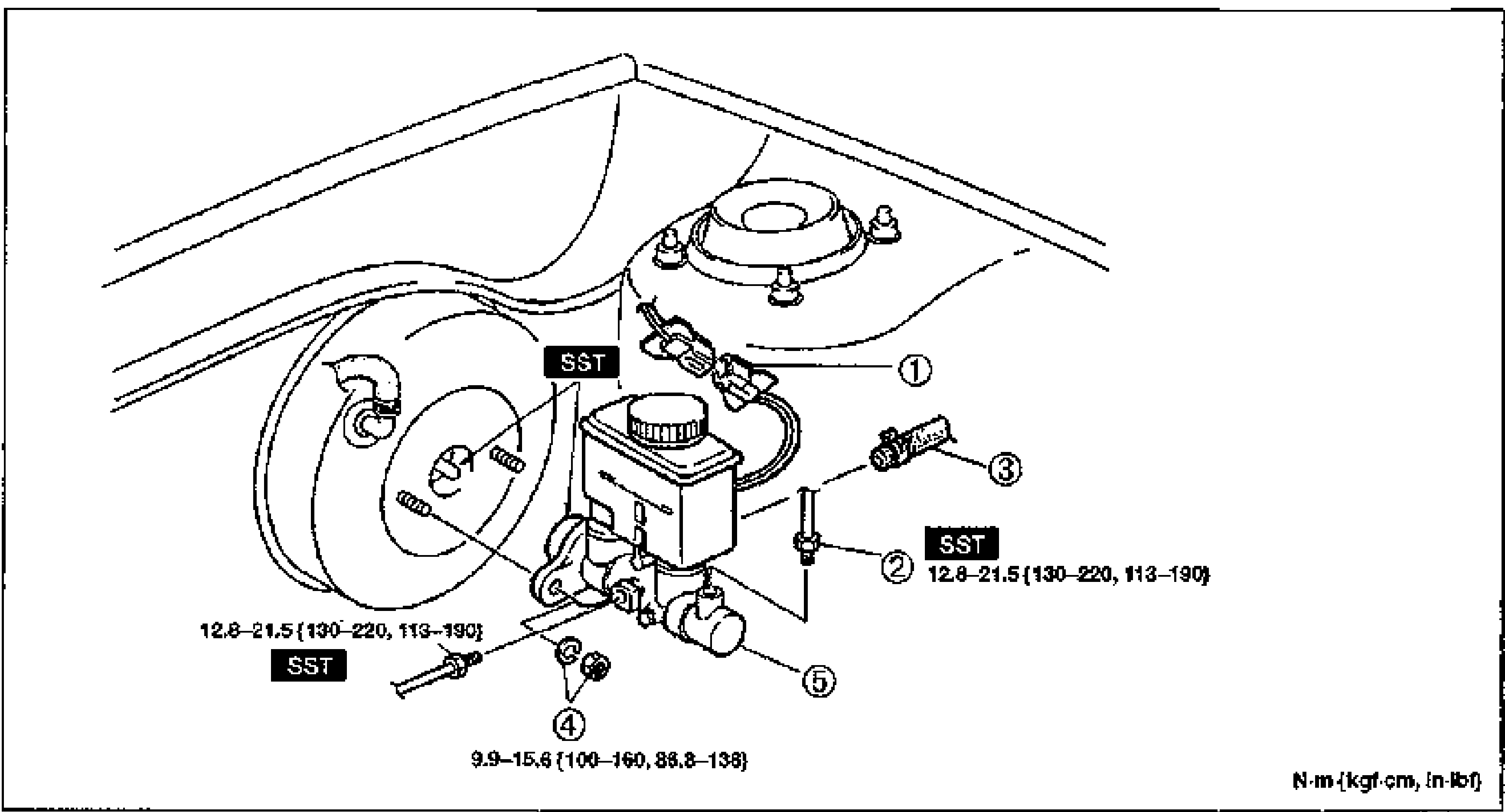
CONVENTIONAL BRAKE SYSTEM
P-14Exploded view of the master cylinder / power brake unit assembly in the engine compartment. Numbered balloon callouts: (1) fluid level sensor connector, (2) brake pipe with SST flare-nut wrench (tightening torque 12.8–21.5 {130–220, 113–190}), (3) hose (MTX), (4) nuts and washers with SST (tightening torque 12.8–21.5 {130–220, 113–190}; also 9.9–15.6 {100–160, 86.8–138}), (5) master cylinder. Torque values in N·m {kgf·cm, in·lbf}.
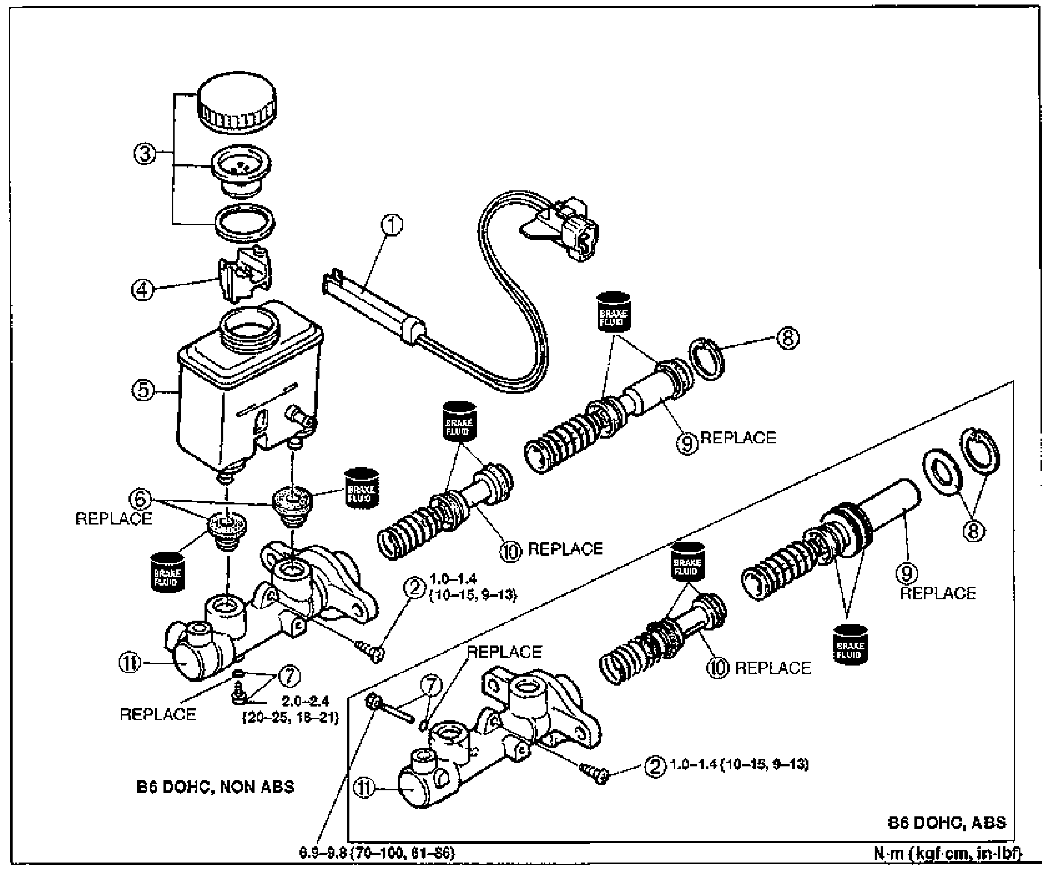
CONVENTIONAL BRAKE SYSTEM
P-17Exploded view of the brake master cylinder disassembly. Main diagram is labeled B6 DOHC, NON ABS; an inset at the lower right is labeled B6 DOHC, ABS. Numbered balloon callouts: (1) fluid level sensor, (2) screw, (3) cap set, (4) float, (5) reservoir, (6) bushings (REPLACE), (7) stop screw and O-ring (NON ABS) / stop pin and O-ring (ABS), (8) snap ring, (9) primary piston assembly (REPLACE), (10) secondary piston assembly (REPLACE), (11) master cylinder body. BRAKE FLUID application points are marked on the pistons. Torque values: screw (2) 1.0–1.4 {10–15, 9–13}; stop screw (7) 2.0–2.4 {20–25, 18–21}; lower-left value 6.9–9.8 {70–100, 61–86}. Units N·m {kgf·cm, in·lbf}.
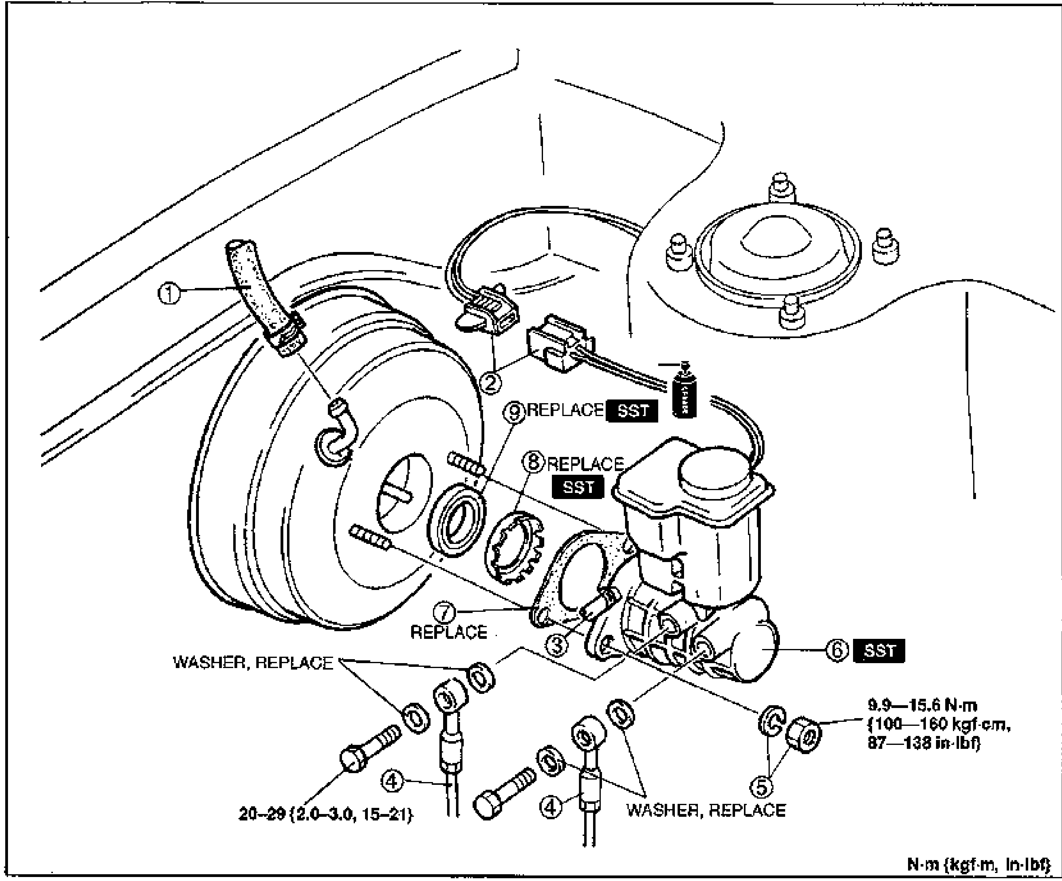
CONVENTIONAL BRAKE SYSTEM
P-19Exploded view of the master cylinder (K8 DOHC) and power brake unit assembly in the engine compartment. Numbered balloon callouts: (1) vacuum hose, (2) fluid level sensor, (3) hose (MTX), (4) brake pipe, (5) nuts and washers, (6) master cylinder (SST), (7) gasket (REPLACE), (8) retainer (REPLACE, SST), (9) seal and plate assembly (REPLACE, SST). WASHER, REPLACE noted at the brake-pipe banjo joints. Torque values: 20–29 {2.0–3.0, 15–21} for the lower bolts and 9.9–15.6 N·m {100–160 kgf·cm, 87–138 in·lbf} at the master cylinder. Units N·m {kgf·m, in·lbf}.
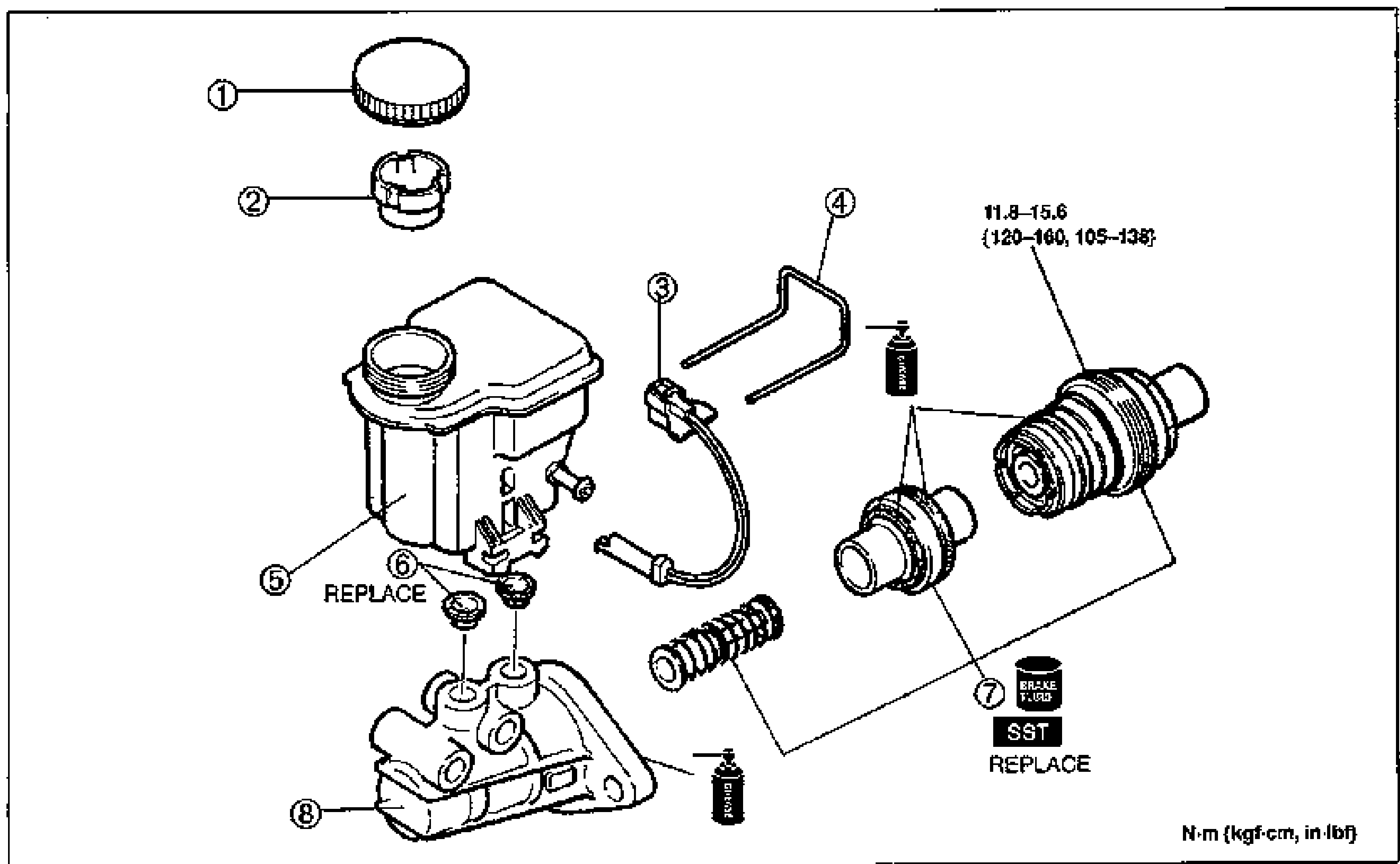
CONVENTIONAL BRAKE SYSTEM - MASTER CYLINDER (K8 DOHC) Disassembly / Assembly / Inspection
P-22Exploded view of the master cylinder disassembly. Shows the cap, tank filter, fluid level sensor, tank retainer, reservoir tank, grommet, primary and secondary piston assemblies (springs and cups), and master cylinder body. SST tool marked at the cap and BRAKE FLUID/REPLACE annotations. Numbered balloon callouts 1-8 with tightening torque. Torque units: N·m (kgf-cm, in-lbf).
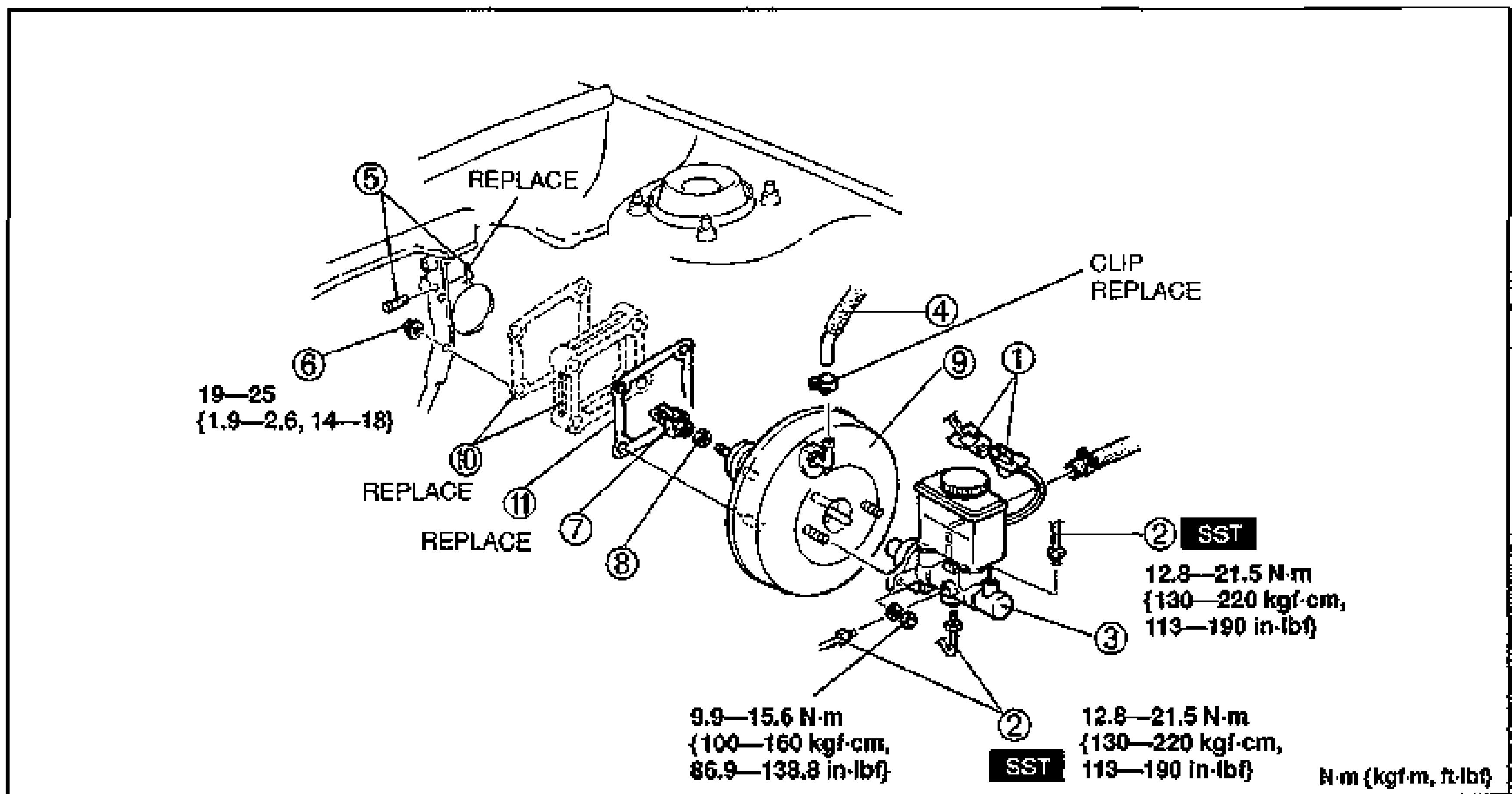
Power Brake Unit - Check Valve Inspection, Removal/Installation (B6 DOHC)
P-28Exploded view of the power brake unit removal/installation (B6 DOHC) showing numbered balloon callouts 1-11: connector, brake pipe, master cylinder assembly, vacuum hose, spring clip and clevis pin, nut, fork, nut, power brake unit, gasket/spacer, gasket. REPLACE labels mark parts to renew. CLIP REPLACE marks the vacuum hose clip. Torque values shown: 19—25 N·m {1.9—2.6, 14—18}, 9.9—15.6 N·m {100—160 kgf·cm, 86.9—138.8 in·lbf}, 12.8—21.5 N·m {130—220 kgf·cm, 113—190 in·lbf} (two SST locations).
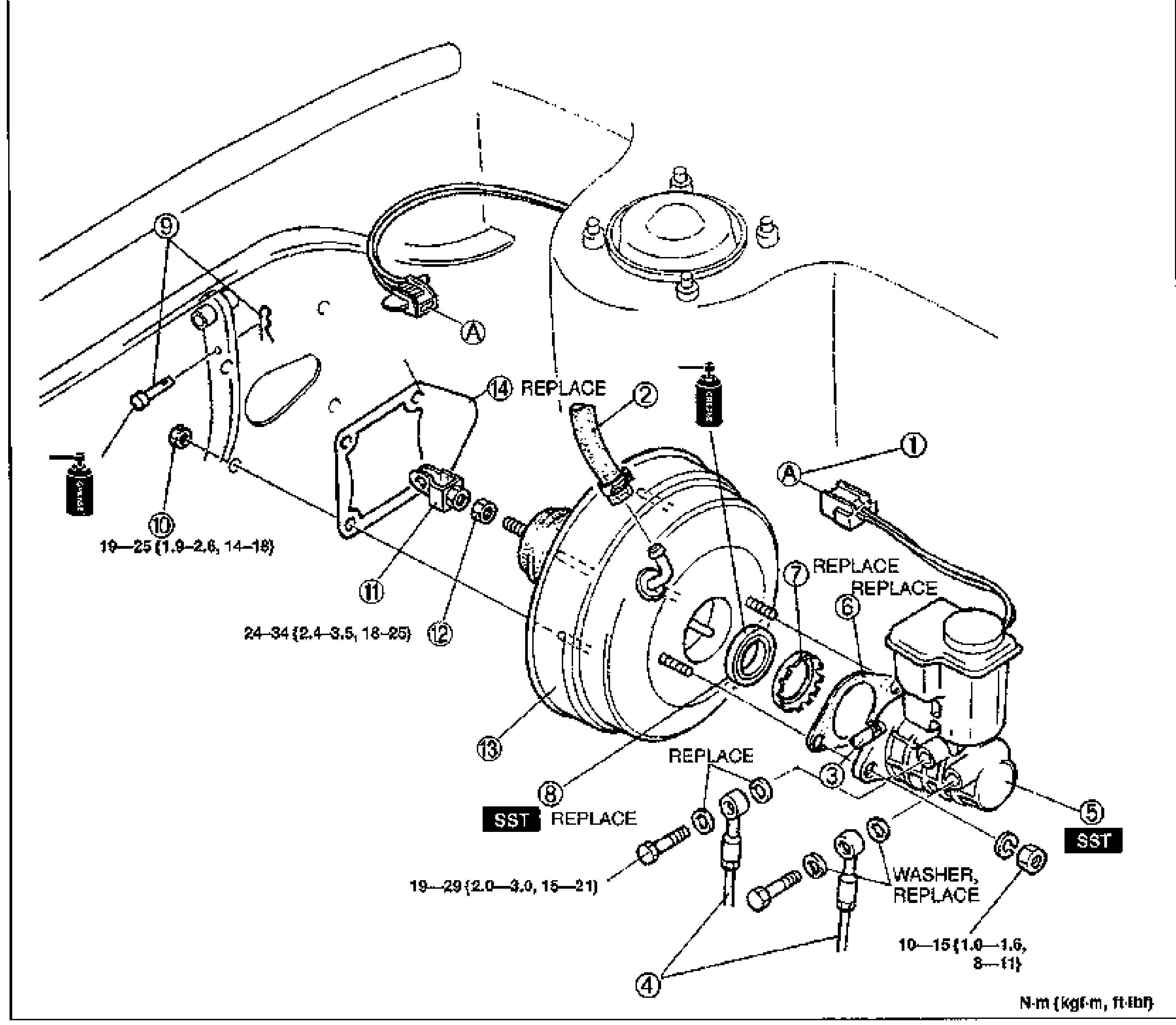
Power Brake Unit - Removal / Installation (K8 DOHC)
P-29Exploded view of the power brake unit removal/installation (K8 DOHC) showing numbered balloon callouts 1-14: connector, vacuum hose, hose (MTX), brake pipe, master cylinder assembly, gasket, retainer, seal and plate assembly, spring clip and clevis pin, nut, fork, nut, power brake unit, gasket. REPLACE labels mark several parts (vacuum hose, gasket items, washer). Two SST locations marked. Torque values: 19—25 {1.9—2.6, 14—18}, 24—34 {2.4—3.5, 18—25}, 19—29 {2.0—3.0, 15—21}, 10—15 {1.0—1.6, 8—11}.
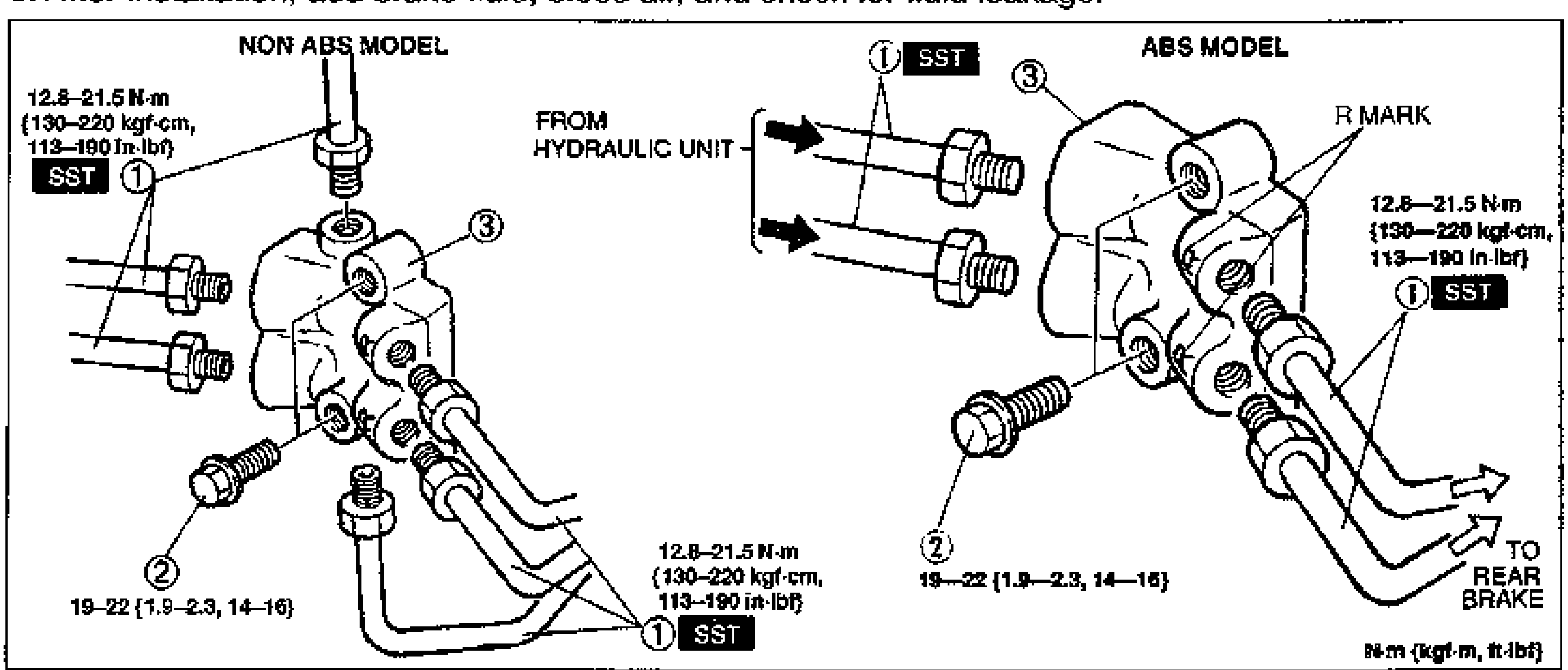
Dual Proportioning Valve - Inspection, Replacement
P-30Exploded view of the dual proportioning valve replacement showing NON ABS MODEL (left) and ABS MODEL (right). Numbered balloon callouts: 1 brake pipe (SST), 2 bolt, 3 dual proportioning valve. Labels FROM HYDRAULIC UNIT, TO REAR BRAKE, R MARK. Torque values: 12.8—21.5 N·m {130—220 kgf·cm, 113—190 in·lbf} and 19—22 {1.9—2.3, 14—16}.
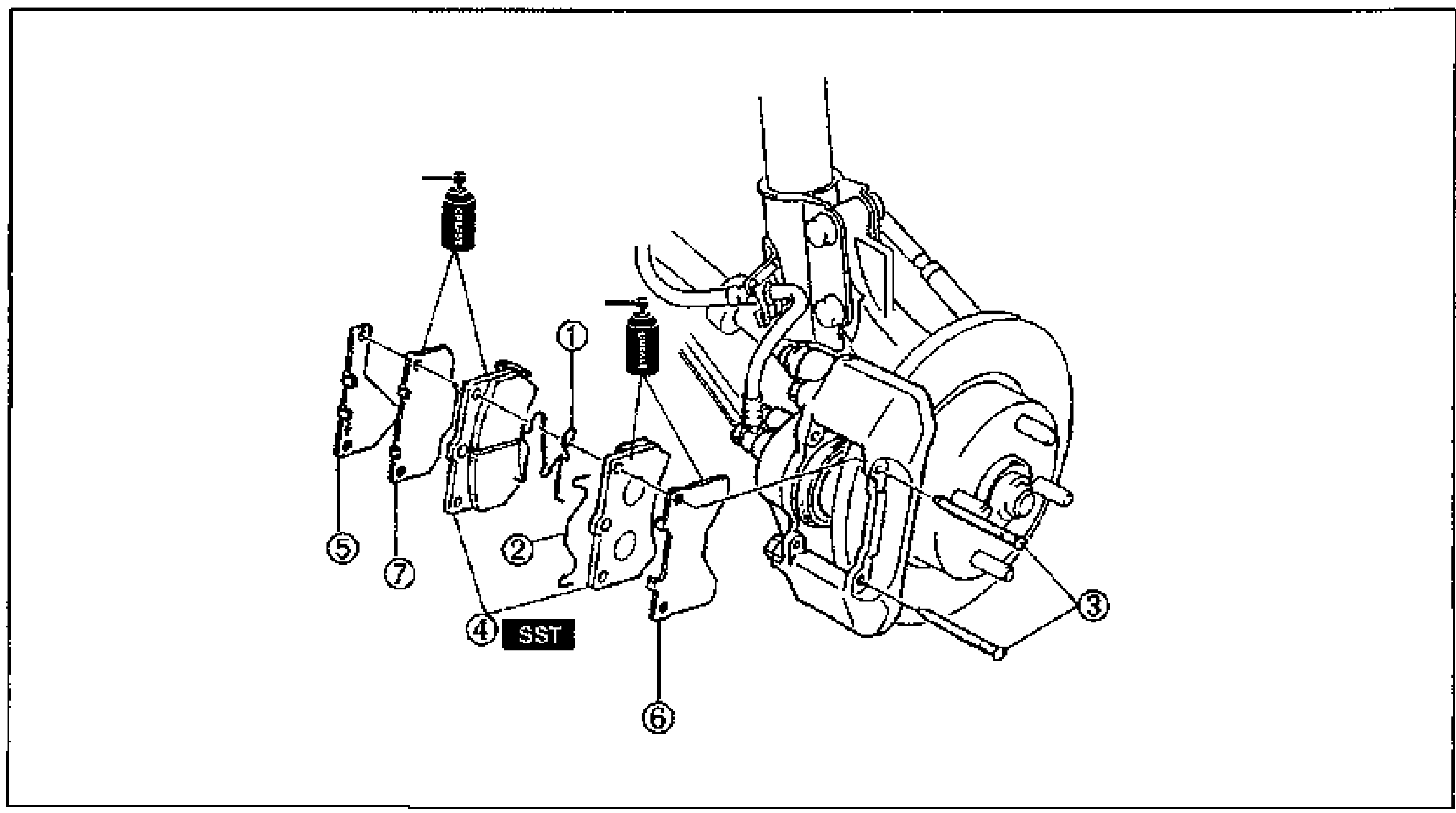
Front Brake (Disc) - Disc pad Quick inspection, Replacement, Installation Note
P-32Exploded view of the front disc brake pad replacement showing numbered balloon callouts 1-7: M-spring, W-pin, pad pin, disc pad (SST), anti-squeak shim, outer shim, inner shim. Shows the caliper, rotor, and shims in exploded order.
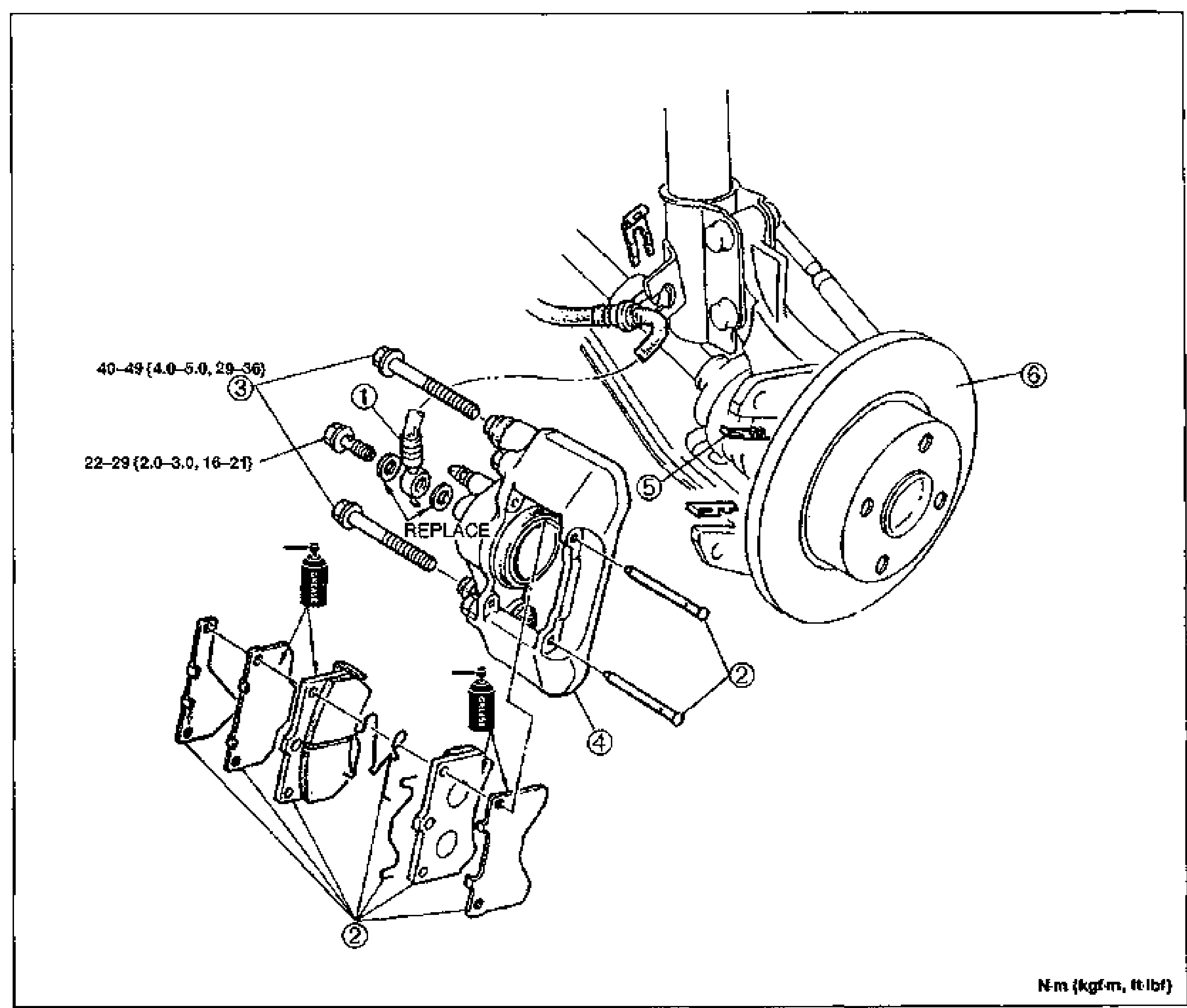
Conventional Brake System — Removal / Installation (Caliper)
P-33Exploded view of the rear disc brake caliper assembly mounted to the knuckle/hub. Shows numbered balloon callouts 1-6 for the flexible hose, disc pad assembly, mounting bolts, caliper body (marked REPLACE), guide plate and disc plate (rotor). Tightening torque labels point to the upper bolt (40-49 N·m {4.0-5.0, 29-36}) and lower bolt (22-29 N·m {2.0-3.0, 16-21}). Unit note bottom-right: N·m (kgf·m, ft-lbf).
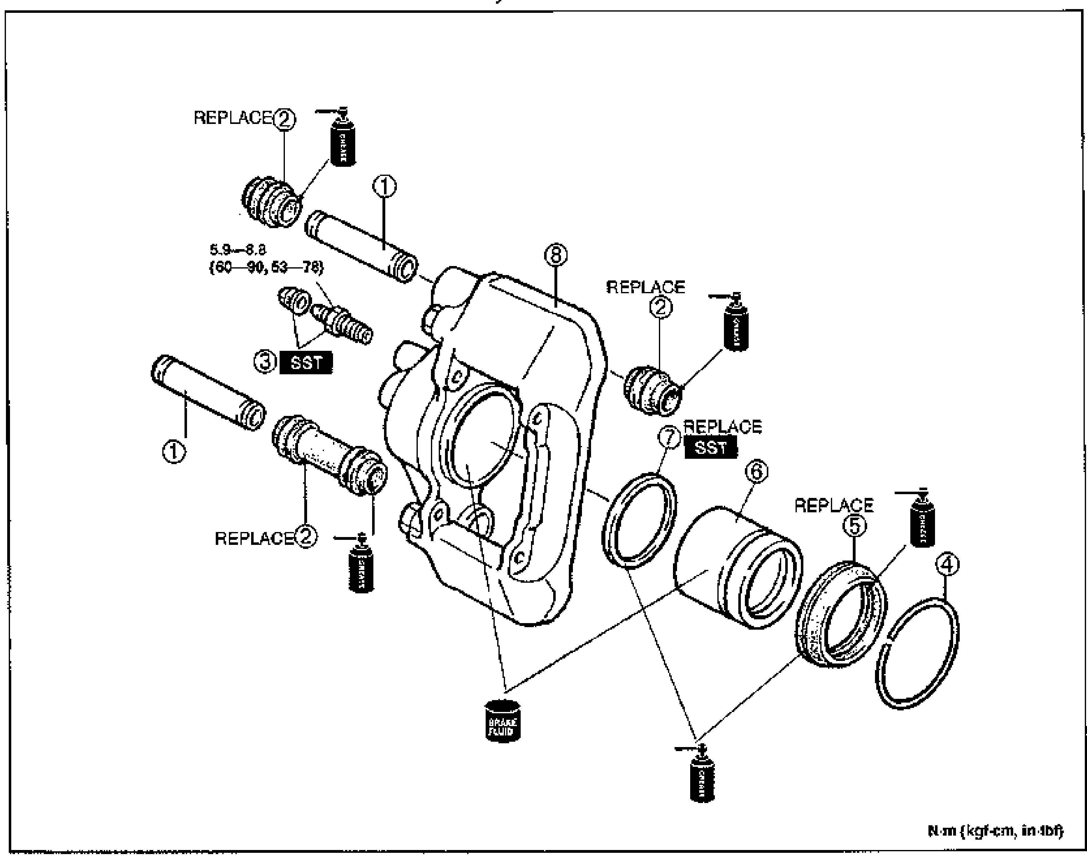
Conventional Brake System — Caliper Disassembly / Inspection / Assembly
P-35Exploded view of the brake caliper assembly with numbered balloon callouts 1-8: sleeve pins, boots (marked REPLACE), rubber cap and bleeder screw (marked SST), retaining ring, dust seal, piston, piston seal (marked REPLACE, SST) and caliper body. Grease and brake-fluid application icons are shown at several joints. Tightening torque label points to the sleeve pin: 5.9-8.8 N·m {60-90, 53-78}. Unit note bottom-right: N·m (kgf·cm, in-lbf).
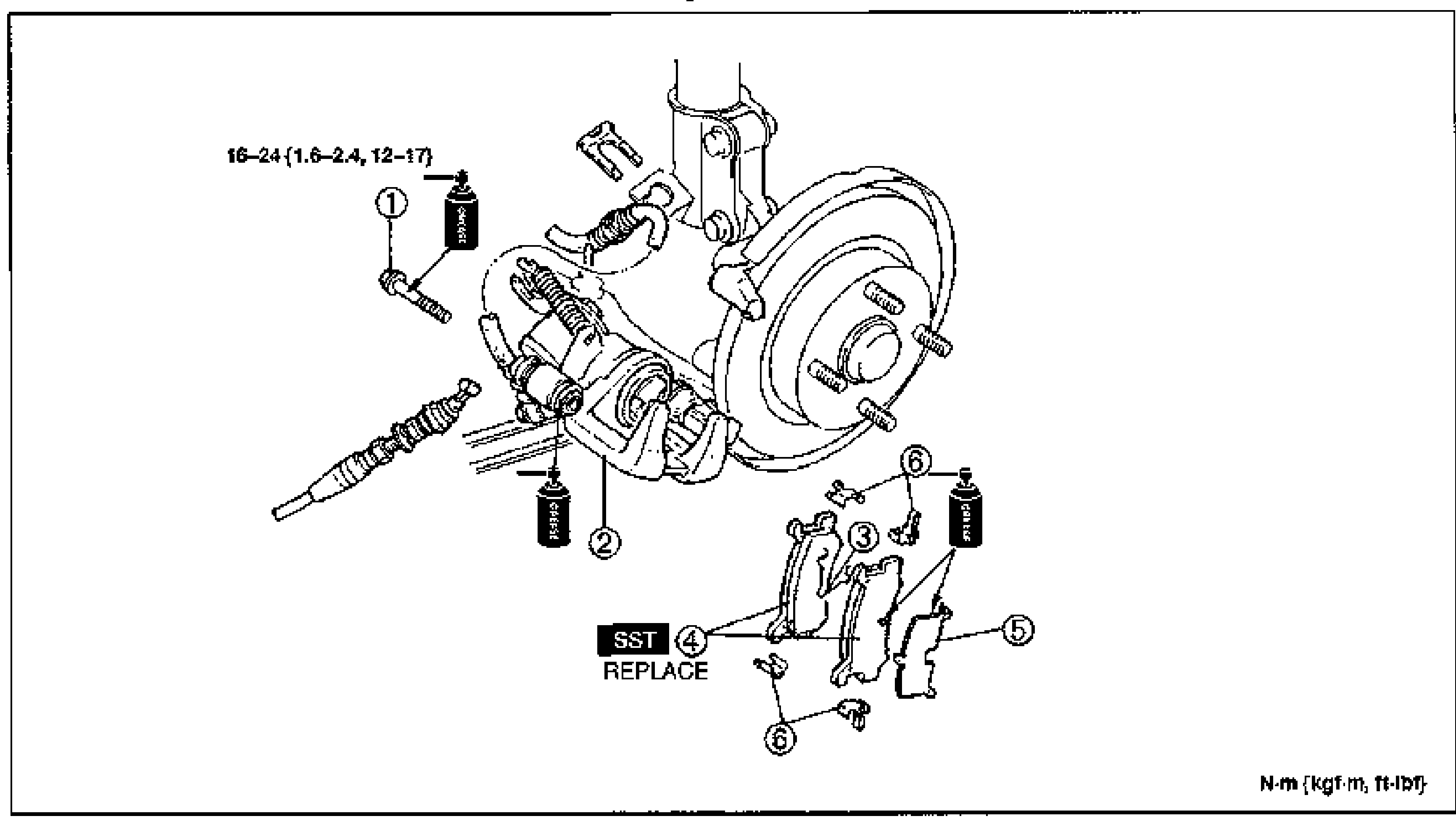
Conventional Brake System — Rear Brake (Disc): Quick Inspection & Disc Pad Replacement
P-37Exploded view of the rear disc brake / caliper assembly with numbered balloon callouts 1-6: bolt, caliper assembly, V-spring, disc pad (marked SST, REPLACE), shim and guide plate, around the hub/rotor. Grease application icons at several points. Tightening torque label points to the bolt: 16-24 N·m {1.6-2.4, 12-17}. Unit note bottom-right: N·m (kgf·m, ft-lbf).
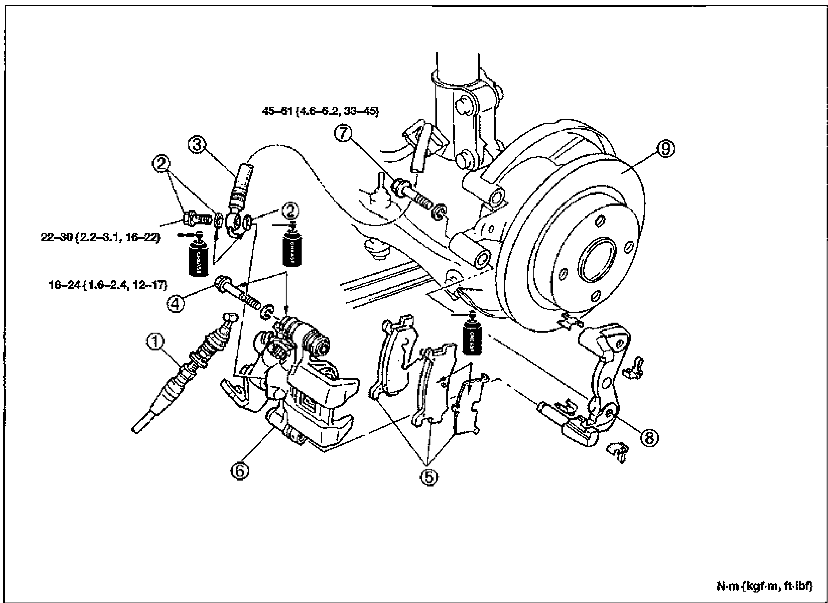
Conventional Brake System — Rear Caliper Removal / Installation
P-38Exploded view of the rear disc brake / caliper assembly with numbered balloon callouts 1-9: parking cable, connector and gasket, flexible hose, bolt, disc pad assembly, caliper assembly, bolt, mounting support and disc plate (rotor). Grease application icons at several points. Tightening torque labels: bolt 7 = 45-61 N·m {4.6-6.2, 33-45}; connector/bolt 22-30 N·m {2.2-3.1, 16-22}; bolt 4 = 16-24 N·m {1.6-2.4, 12-17}. Unit note bottom-right: N·m (kgf·m, ft-lbf).
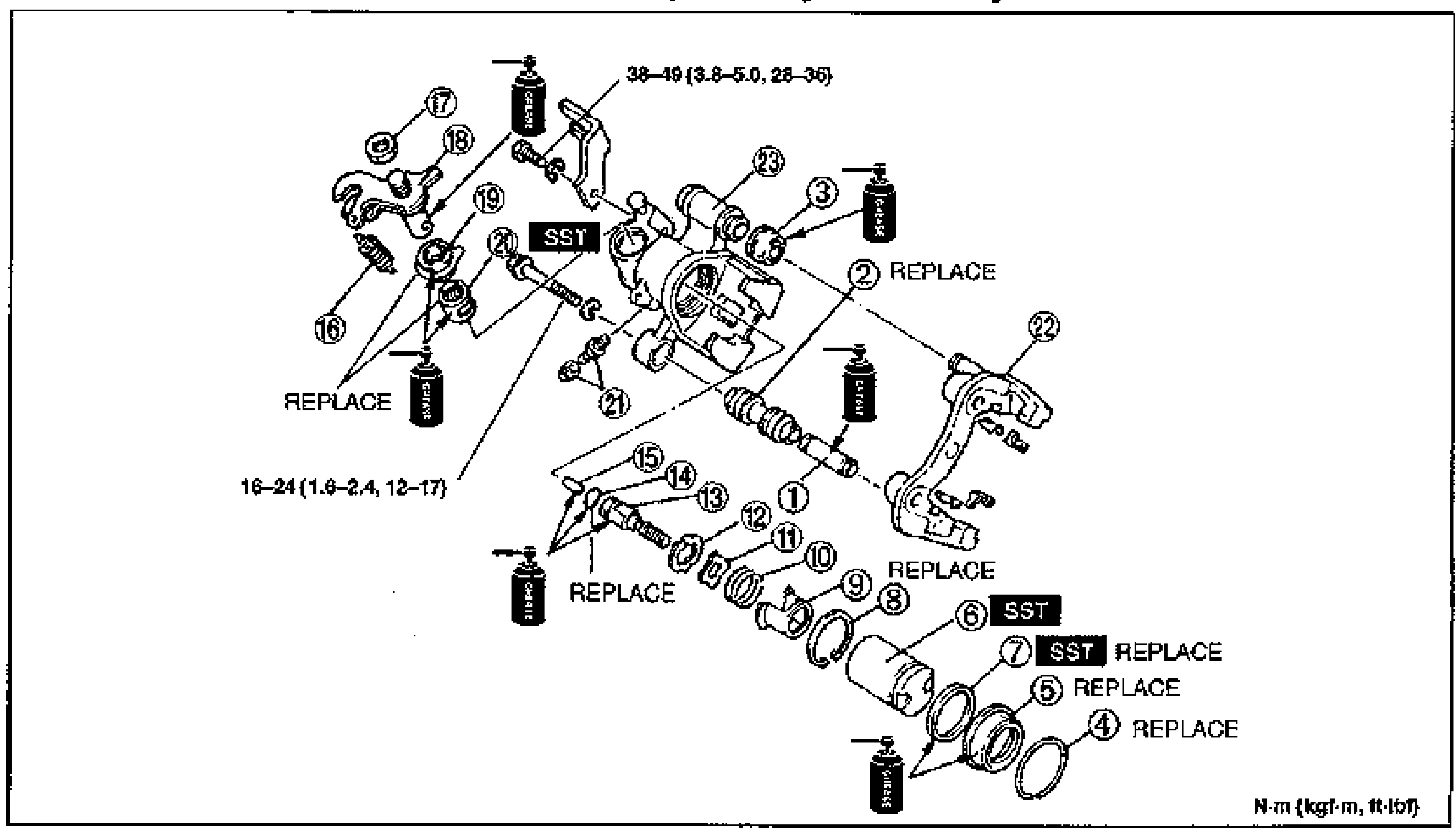
Conventional Brake System — Rear Caliper Disassembly / Inspection / Assembly
P-40Exploded view of the rear (parking-brake-integrated) disc brake caliper assembly with numbered balloon callouts 1-23 covering guide pin, pin boot, bushing, retaining ring, dust seal, piston, piston seal, snap ring, spring case, spring, washer, stopper, adjuster spindle, O-ring, connecting link, spring, nut, operating lever, boot, needle bearing, rubber cap and bleeder screw, mounting support and caliper body. Several parts marked REPLACE and SST. Grease application icons throughout. Tightening torque labels: 38-49 N·m {3.8-5.0, 28-36} and 16-24 N·m {1.6-2.4, 12-17}. Unit note bottom-right: N·m (kgf·m, ft-lbf).
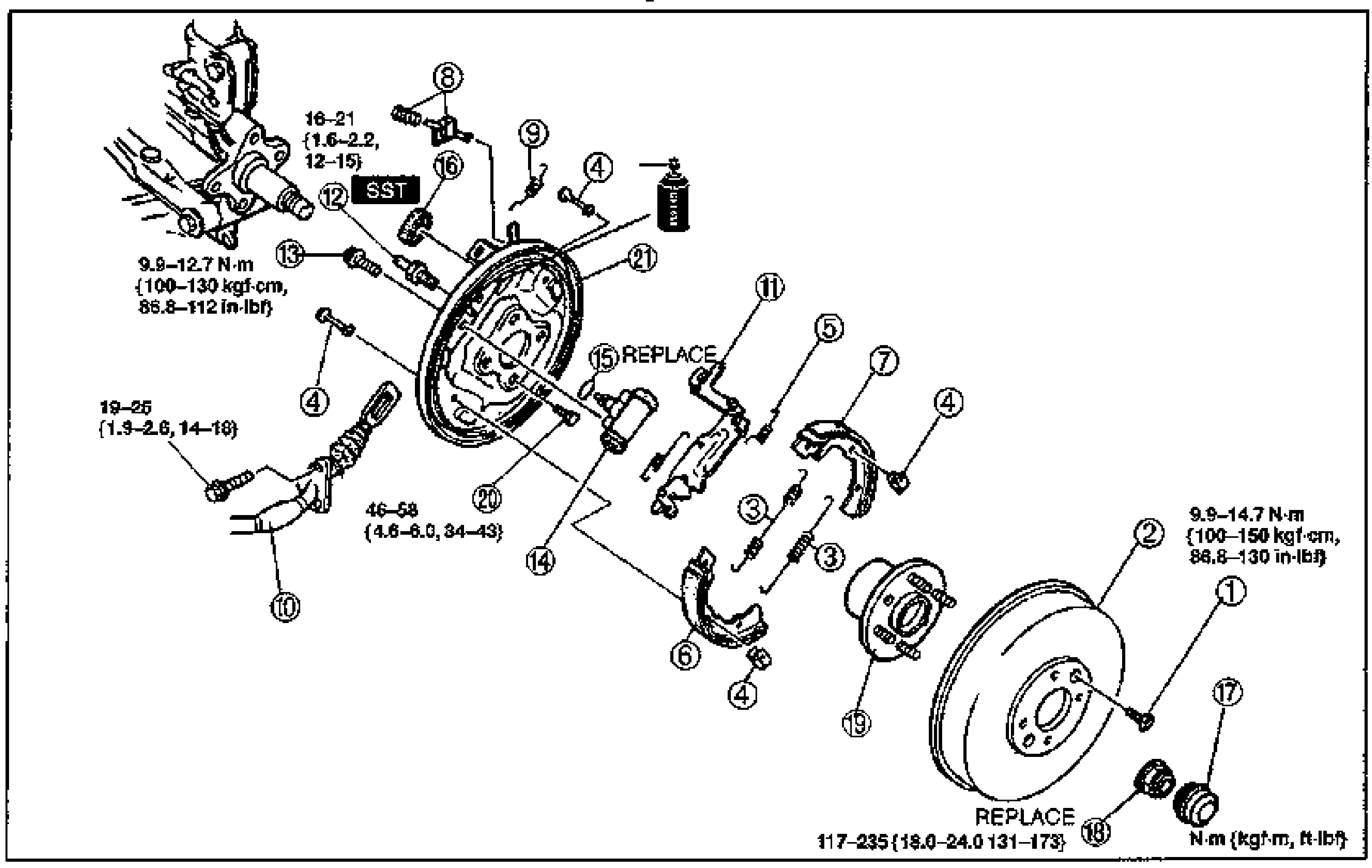
Conventional Brake System — Rear Brake (Drum): Quick Inspection & Removal / Inspection / Installation
P-42Exploded view of the rear drum brake assembly with numbered balloon callouts 1-21: screw, brake drum, return spring, hold pin and spring, anti-rattle spring, brake shoe (leading side), brake shoe (trailing side), stopper spring and clip, return spring, parking brake cable, operating lever assembly, brake pipe, bolt, wheel cylinder assembly, wheel cylinder gasket (marked REPLACE), dust boot, hub cap, locknut (marked REPLACE), wheel hub assembly, bolt and backing plate. Grease/SST markers present. Tightening torque labels: 16-21 N·m {1.6-2.2, 12-15}; 9.9-12.7 N·m {100-130 kgf·cm, 86.8-112 in-lbf}; 19-25 N·m {1.9-2.6, 14-18}; 46-58 N·m {4.6-6.0, 34-43}; 9.9-14.7 N·m {100-150 kgf·cm, 86.8-130 in-lbf}; 117-235 {18.0-24.0, 131-173}. Unit note bottom-right: N·m (kgf·m, ft-lbf).
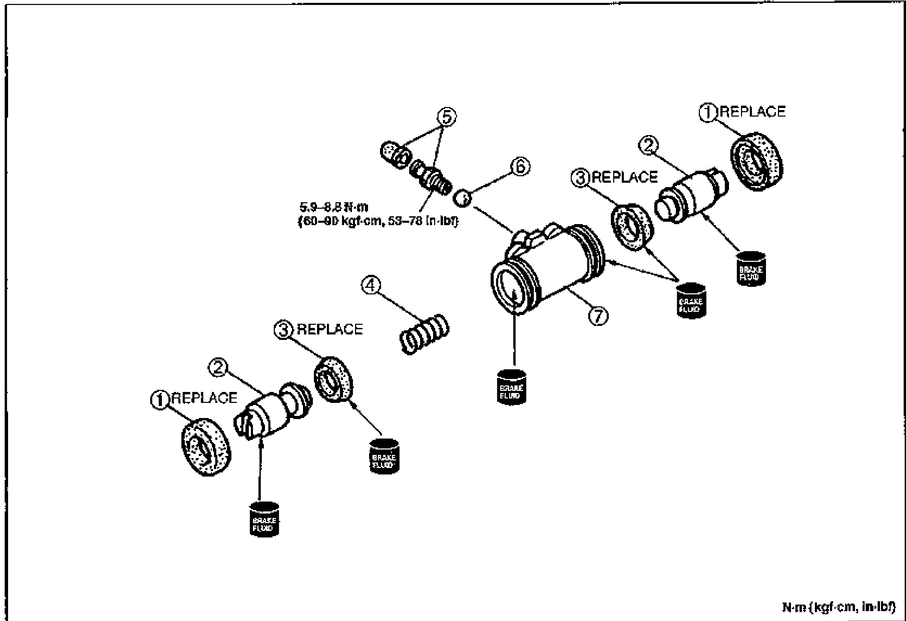
CONVENTIONAL BRAKE SYSTEM
P-44Exploded view of the wheel cylinder showing two mirrored piston/cup/dust-boot assemblies, spring, rubber cup and bleeder screw, steel ball and wheel cylinder body. Balloon callouts numbered 1-7. Parts 1 and 3 marked REPLACE; brake-fluid application points indicated. Bleeder screw tightening torque labeled 5.9—8.8 N·m (60—90 kgf·cm, 53—78 in·lbf).
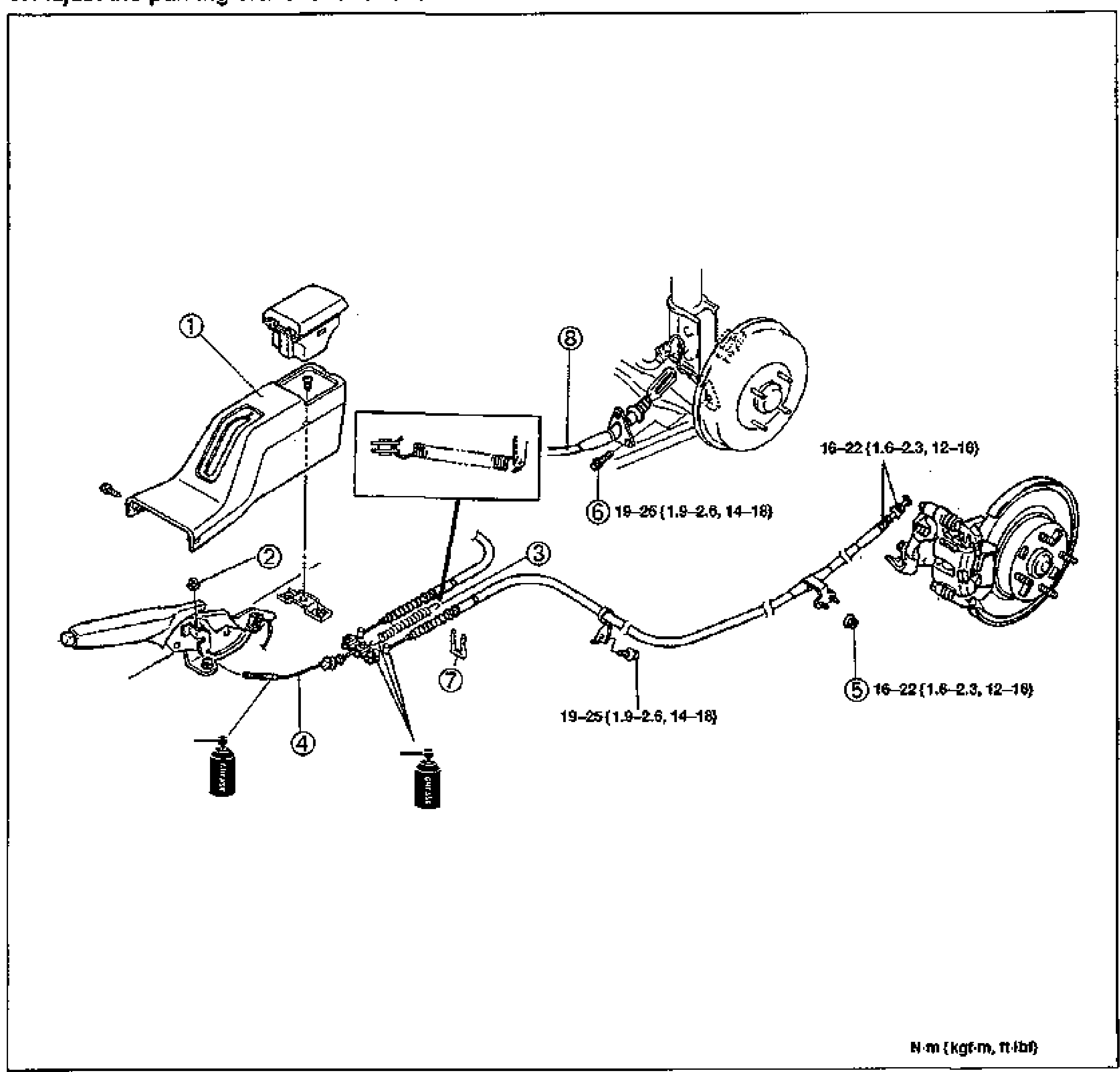
PARKING BRAKE SYSTEM
P-46Exploded view of the parking brake cable assembly. Shows the rear console, parking brake lever with adjusting nut, return spring, front parking cable, rear parking cables routed to both rear drum/disc brakes. Balloon callouts 1-8. Tightening torques labeled: 16—22 N·m {1.6—2.3 kgf·m, 12—16 ft·lbf} and 19—25 N·m {1.9—2.6 kgf·m, 14—18 ft·lbf}. Grease application points indicated.
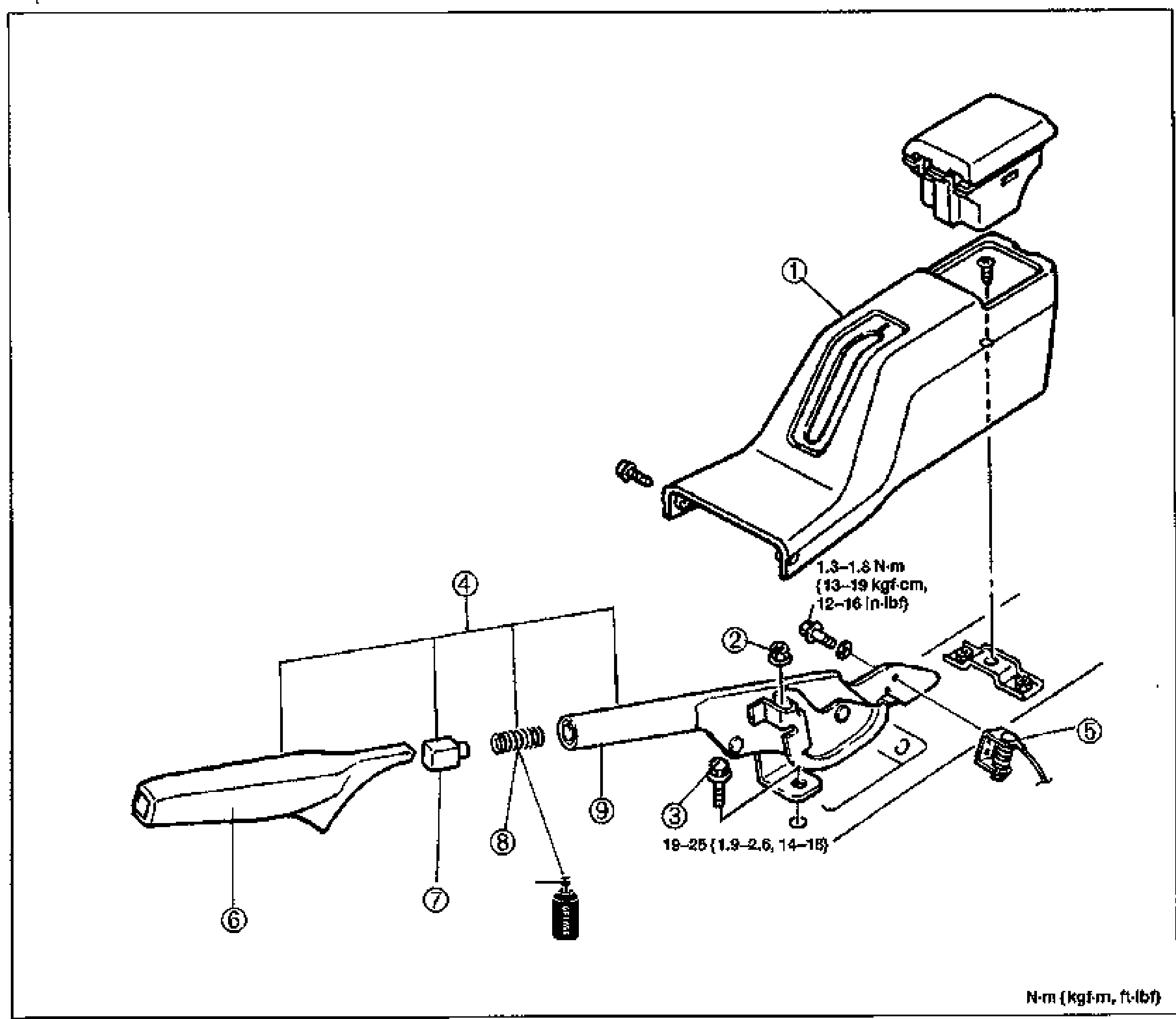
PARKING BRAKE SYSTEM
P-47Exploded view of the parking brake lever assembly with the rear console, adjusting nut, bolt, parking brake lever assembly, parking brake switch, parking lever cap, release button, parking lever spring and parking brake lever. Balloon callouts 1-9. Tightening torques labeled: 1.3—1.8 N·m {13—19 kgf·cm, 12—16 in·lbf} and 19—25 N·m {1.9—2.6, 14—18}. Grease application point indicated.
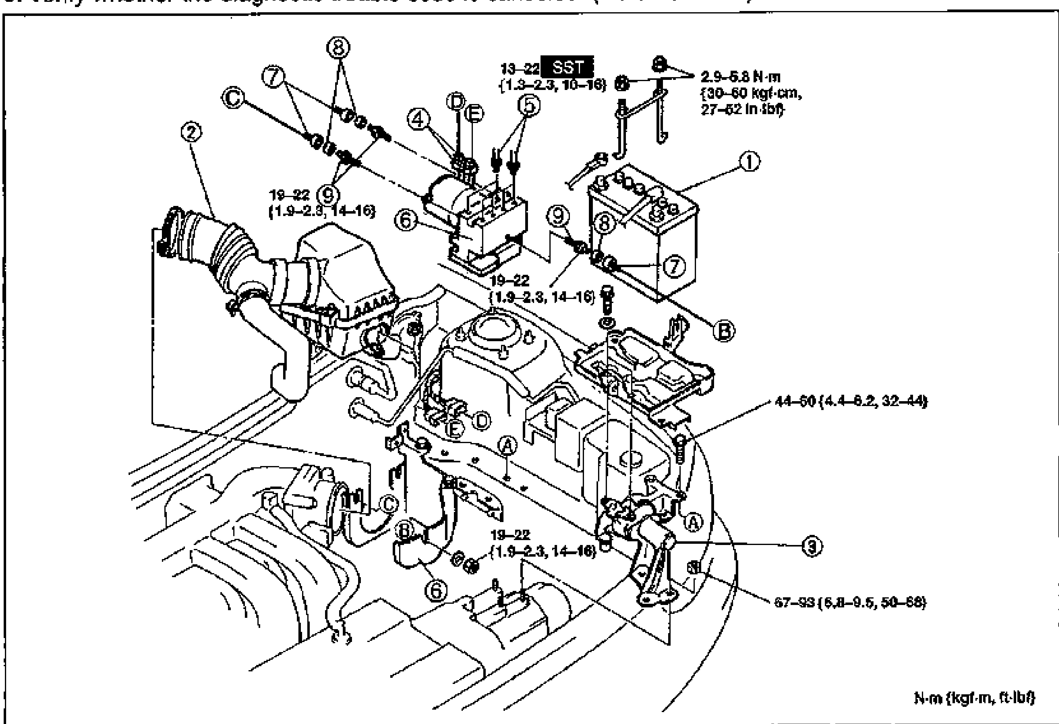
ANTI-LOCK BRAKE SYSTEM
P-70Exploded view of the ABS hydraulic unit installation in the engine bay. Numbered balloon callouts 1-9 identify the battery, air cleaner, mount bushing, connectors, brake pipe, ABS hydraulic unit assembly, casing, mount, and hex stud. Tightening torque values are noted: 13-22 N·m (1.3-2.3 kgf·m, 10-16 ft-lbf) at SST point, 2.9-5.8 N·m (30-60 kgf·cm, 27-52 in-lbf), 19-22 N·m (1.9-2.3 kgf·m, 14-16 ft-lbf), 44-60 N·m (4.4-6.2 kgf·m, 32-44 ft-lbf), 67-93 N·m (6.8-9.5 kgf·m, 50-68 ft-lbf). Letter callouts A-E mark mounting points.
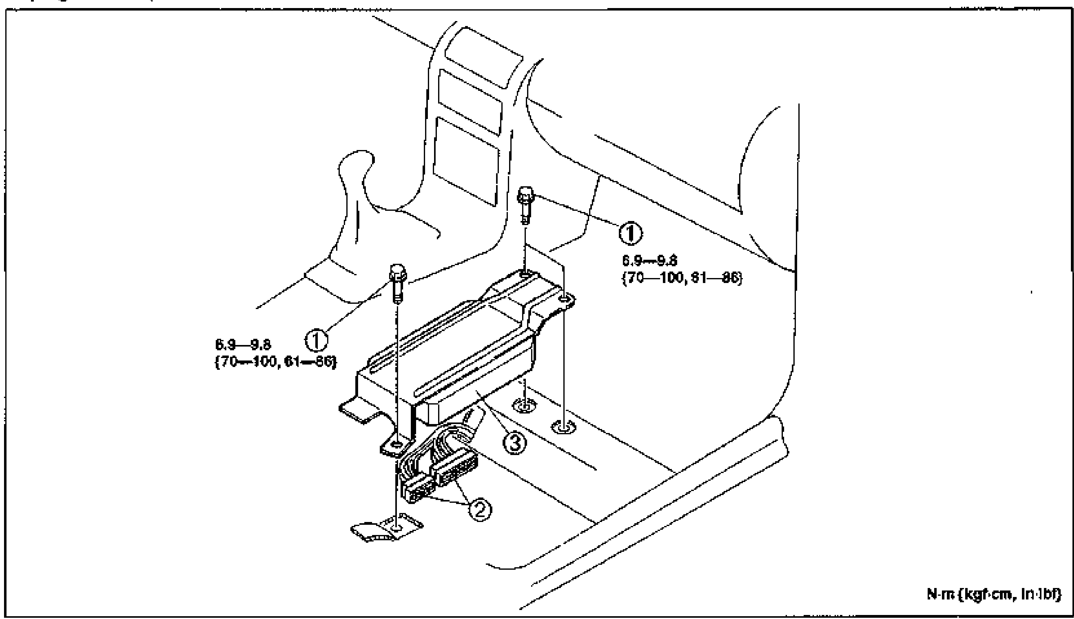
ANTI-LOCK BRAKE SYSTEM
P-71Exploded view of the ABS control module mounted under the passenger seat carpet. Numbered balloon callouts: 1 = Bolt (two, torque 6.9-9.8 N·m {70-100 kgf·cm, 61-86 in-lbf}), 2 = Connector, 3 = ABS control module on its bracket on the floor pan.
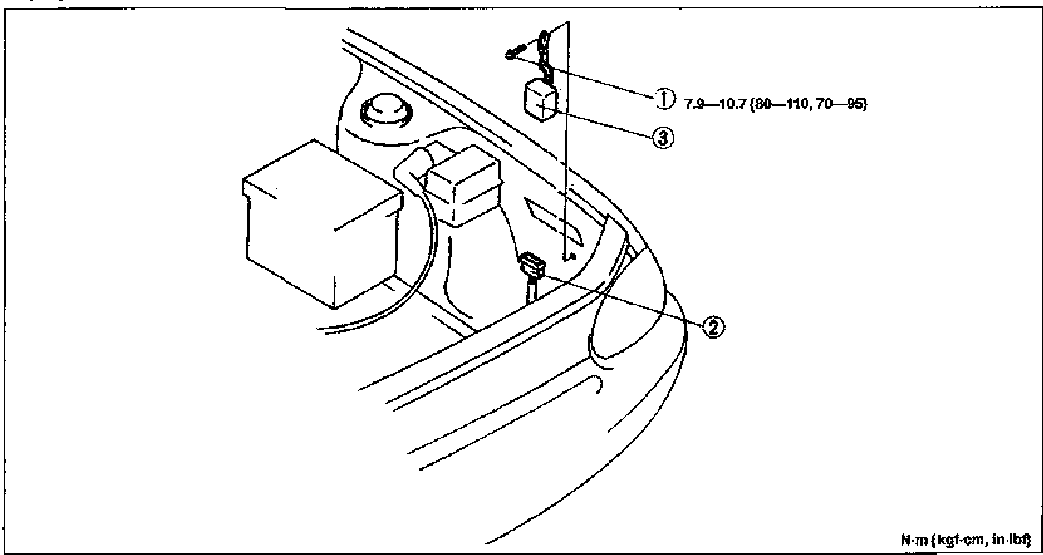
ANTI-LOCK BRAKE SYSTEM
P-72Exploded view of the ABS relay installation in the engine bay. Numbered balloon callouts: 1 = Bolt (torque 7.9-10.7 N·m {80-110 kgf·cm, 70-95 in-lbf}), 2 = Connector, 3 = ABS relay.
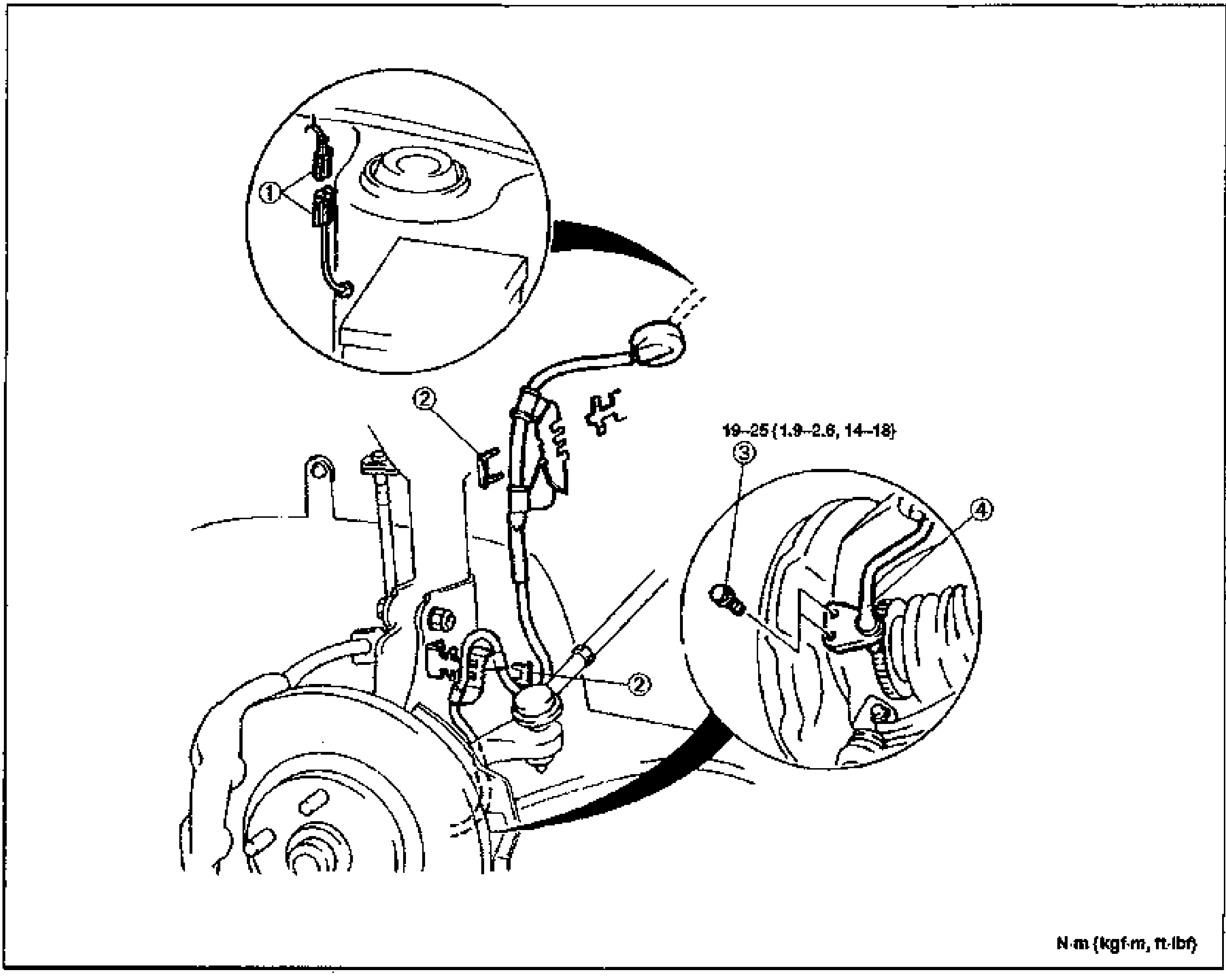
ANTI-LOCK BRAKE SYSTEM — ABS WHEEL-SPEED SENSOR (FRONT)
P-74Exploded/installation view of the front ABS wheel-speed sensor on the front suspension/knuckle assembly. Numbered callouts: (1) connector with magnified inset showing routing, (2) clips along the harness, (3) bolt mounting the sensor, (4) ABS wheel-speed sensor at the hub. Tightening torque marked 19–25 {1.9–2.6, 14–18} for the bolt. Units note N·m {kgf·m, ft·lbf}.
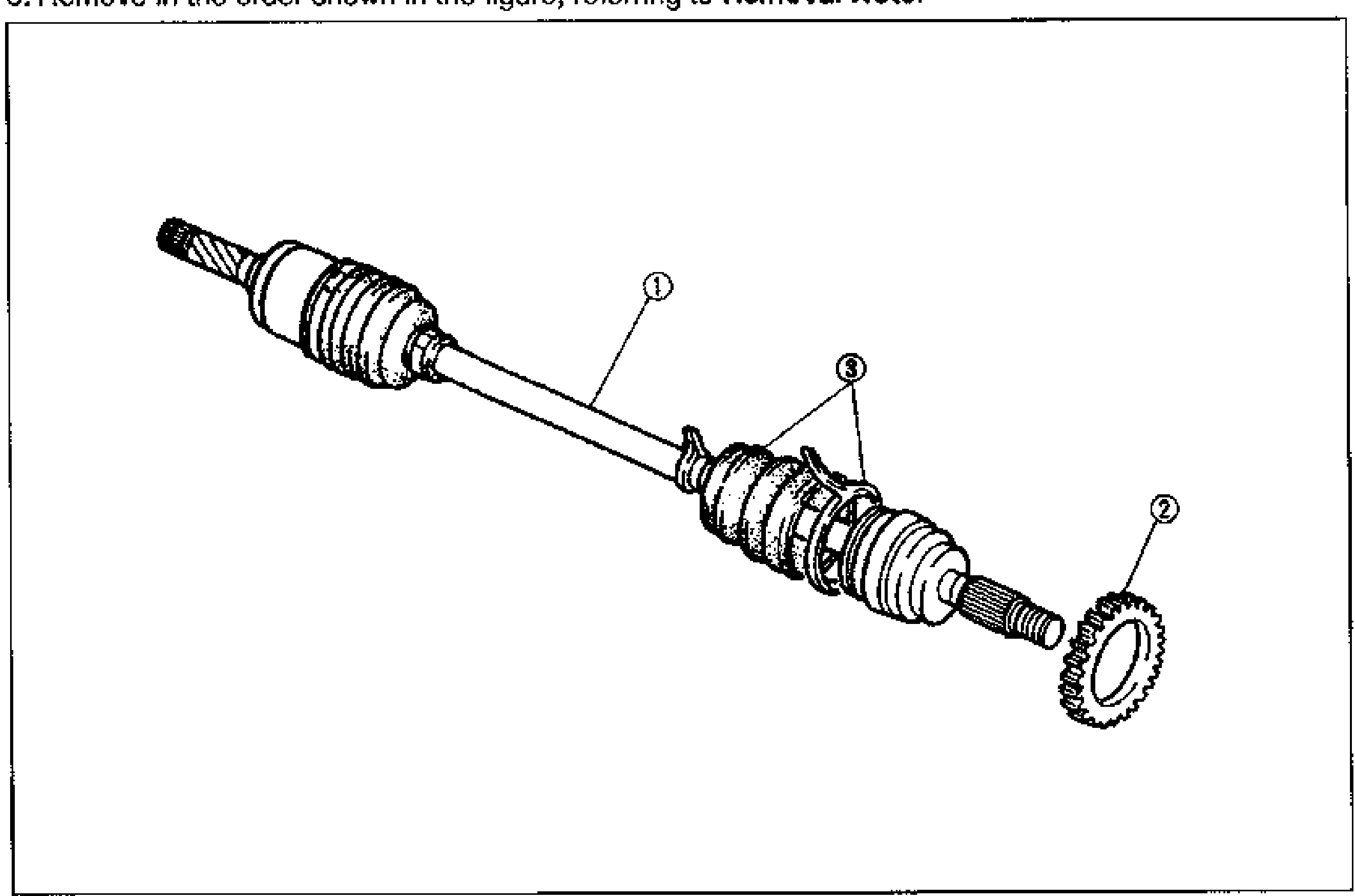
ANTI-LOCK BRAKE SYSTEM — ABS SENSOR ROTOR (FRONT)
P-75Exploded view of the front drive shaft assembly showing the ABS sensor rotor. Callouts: (1) drive shaft, (2) ABS sensor rotor (toothed ring) at the outer end, (3) boot band and boot at the CV joint.
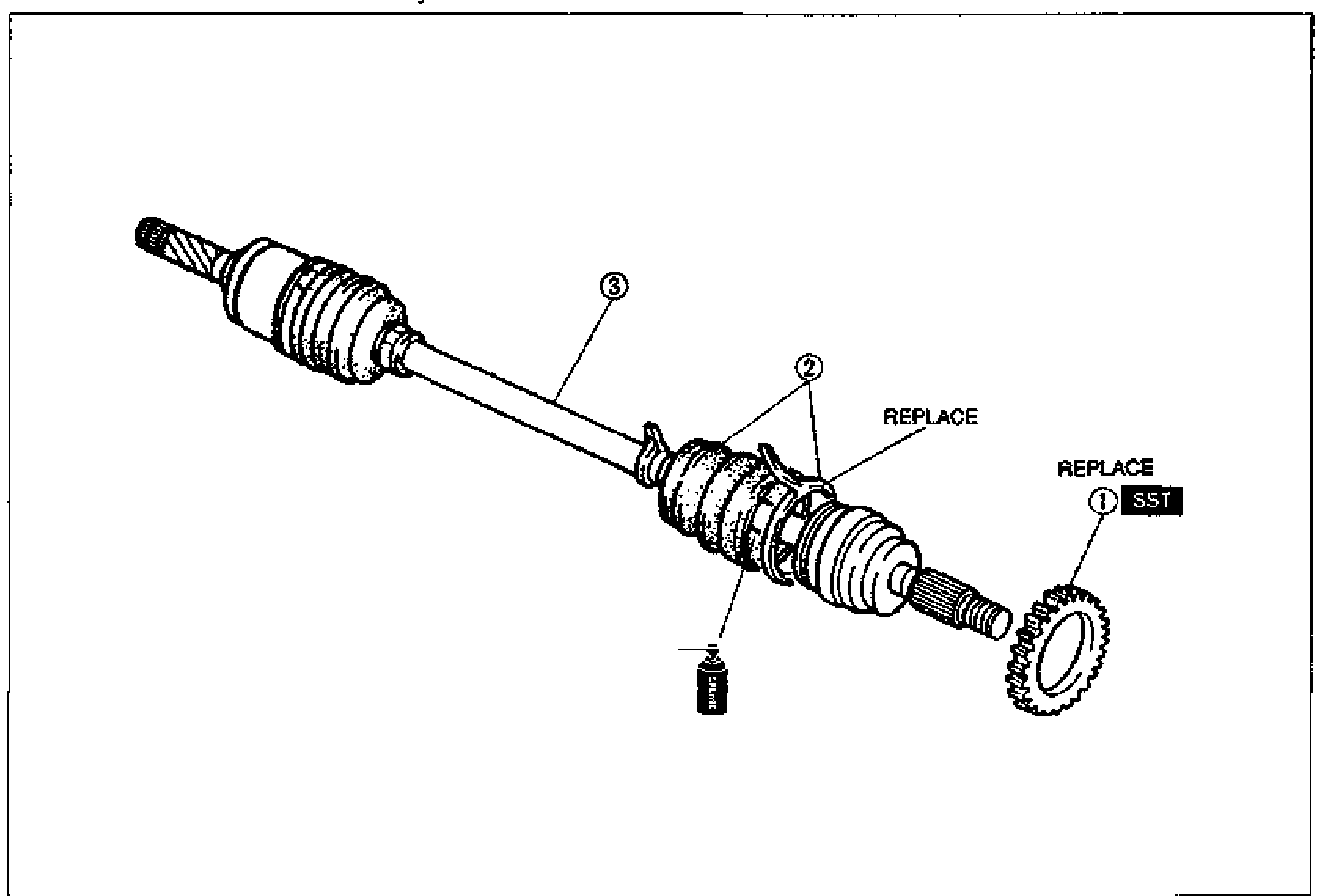
ANTI-LOCK BRAKE SYSTEM — ABS SENSOR ROTOR (FRONT) Installation
P-76Exploded view of the front drive shaft assembly for installation. Callouts: (1) ABS sensor rotor (toothed ring) marked REPLACE and pressed on with SST, (2) boot and boot band marked REPLACE, (3) drive shaft. Adhesive/grease applied at the boot.
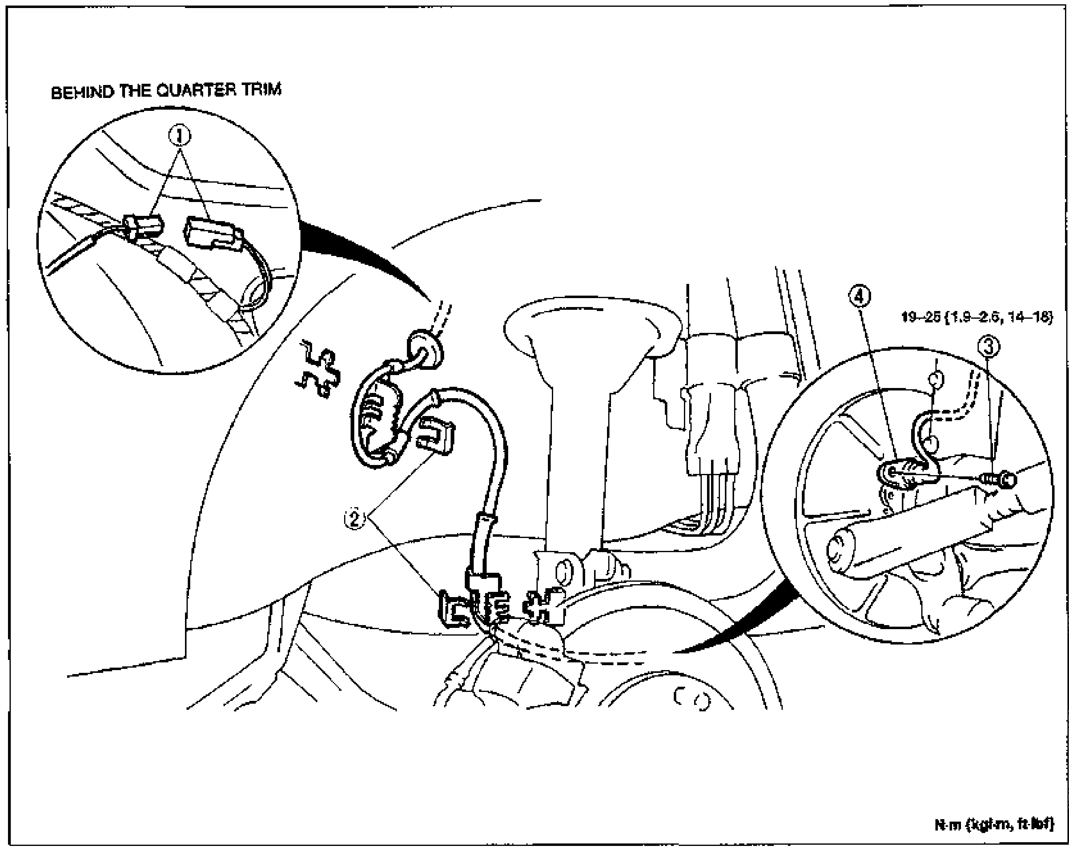
ANTI-LOCK BRAKE SYSTEM — ABS WHEEL-SPEED SENSOR (REAR)
P-77Installation/removal view of the rear ABS wheel-speed sensor. Callouts: (1) connector (with magnified inset 'BEHIND THE QUARTER TRIM' showing two connectors), (2) clips on the harness, (3) bolt, (4) ABS wheel-speed sensor at the rear hub/backing plate. Bolt torque marked 19–25 {1.9–2.6, 14–18}. Units note N·m {kgf·m, ft·lbf}.
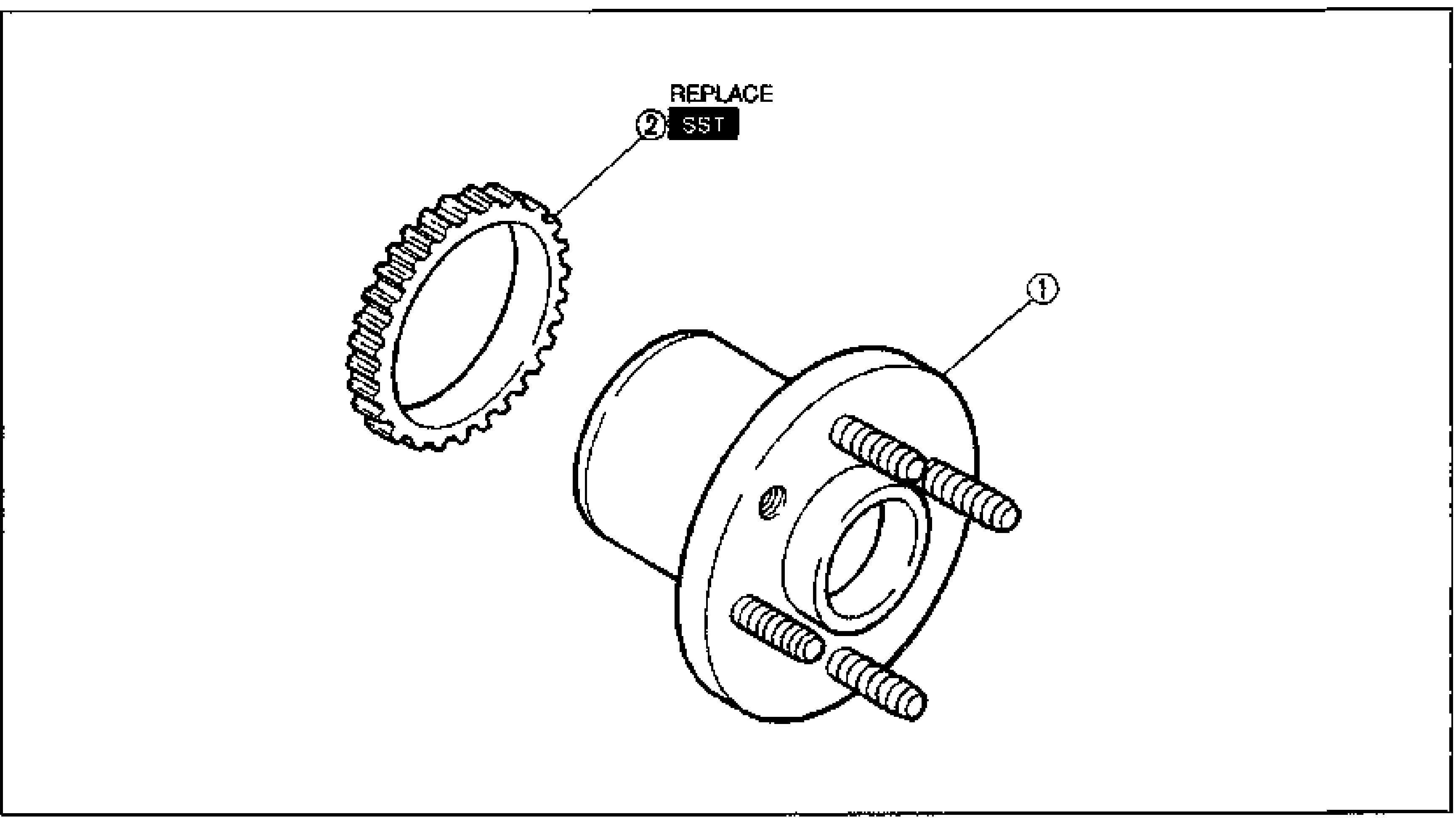
ANTI-LOCK BRAKE SYSTEM — ABS SENSOR ROTOR (REAR)
P-78Exploded view of the rear wheel hub and ABS sensor rotor. Callouts: (1) wheel hub (with studs), (2) ABS sensor rotor (toothed ring) marked REPLACE and installed with SST.
Suspension
R16 diagrams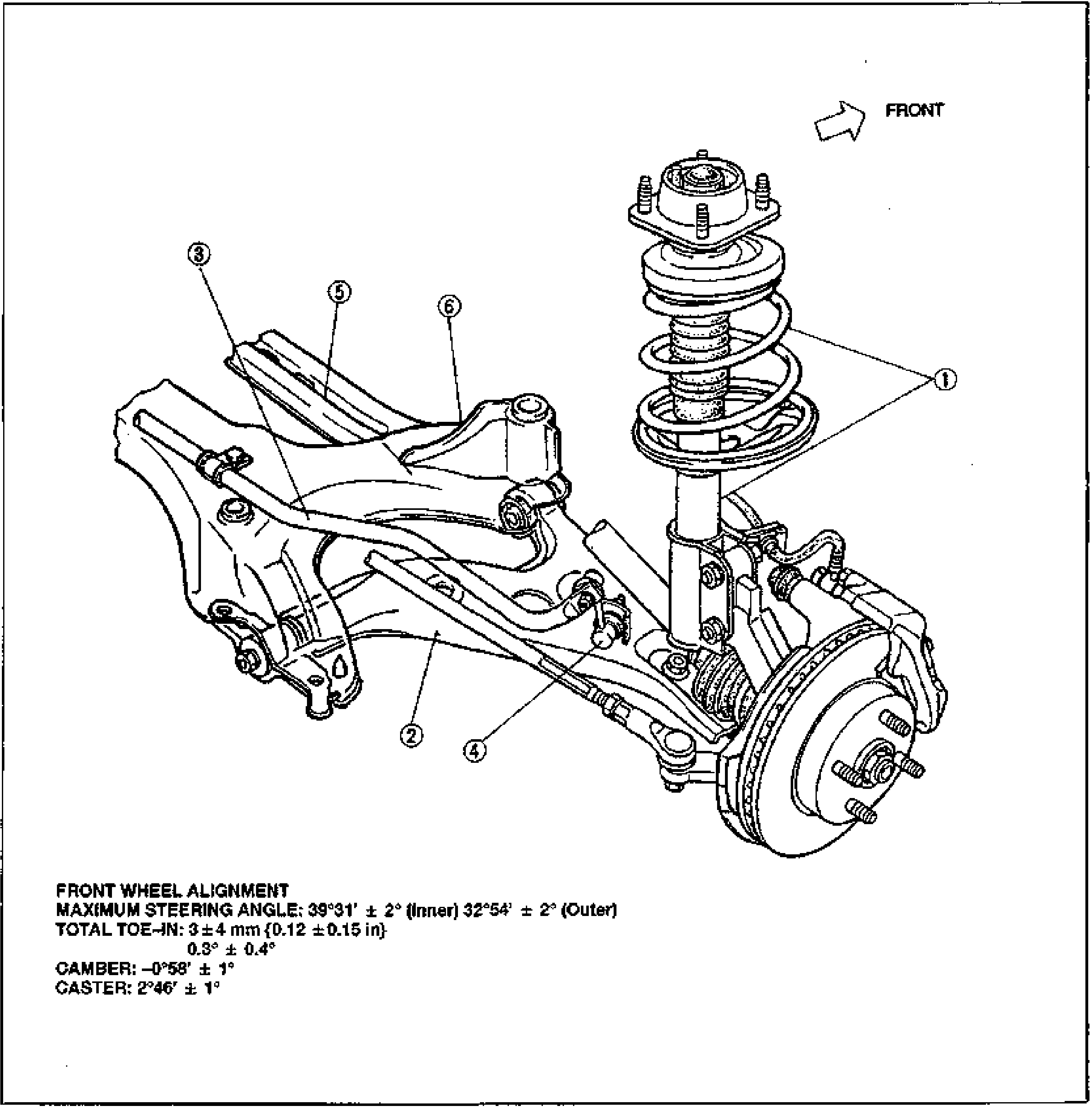
INDEX — FRONT SUSPENSION
R-2Exploded/assembly view of the MX-3 front suspension (strut type) seen from the rear-three-quarter, with a FRONT direction arrow at top right. Numbered balloon callouts 1-6 identify: 1 front shock absorber and spring (coil-over strut), 2 front lower arm, 3 front stabilizer, 4 stabilizer control link, 5 transverse member, 6 front crossmember. Shows the brake disc, hub/knuckle, lower arm and crossmember assembly. Below the figure are front wheel alignment specifications.
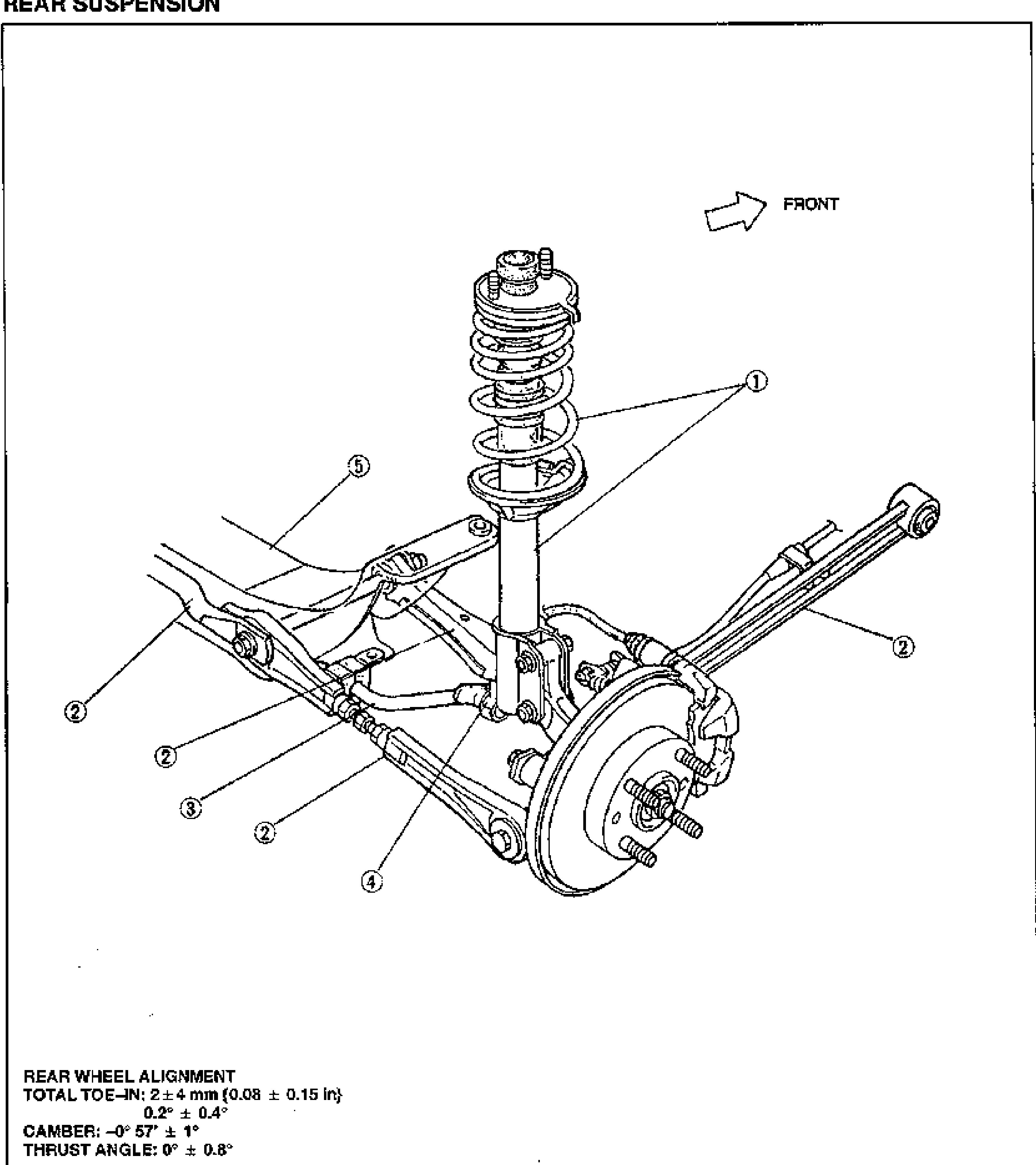
INDEX — REAR SUSPENSION
R-3Exploded/assembly view of the MX-3 rear suspension (strut type) with a FRONT direction arrow at top right. Numbered balloon callouts identify: 1 rear shock absorber and spring (coil-over strut), 2 performance rod / lateral link / trailing link (multiple instances), 3 rear stabilizer, 4 stabilizer control link, 5 rear crossmember. Shows the brake disc/drum, hub, lateral and trailing links and crossmember. Below the figure are rear wheel alignment specifications.
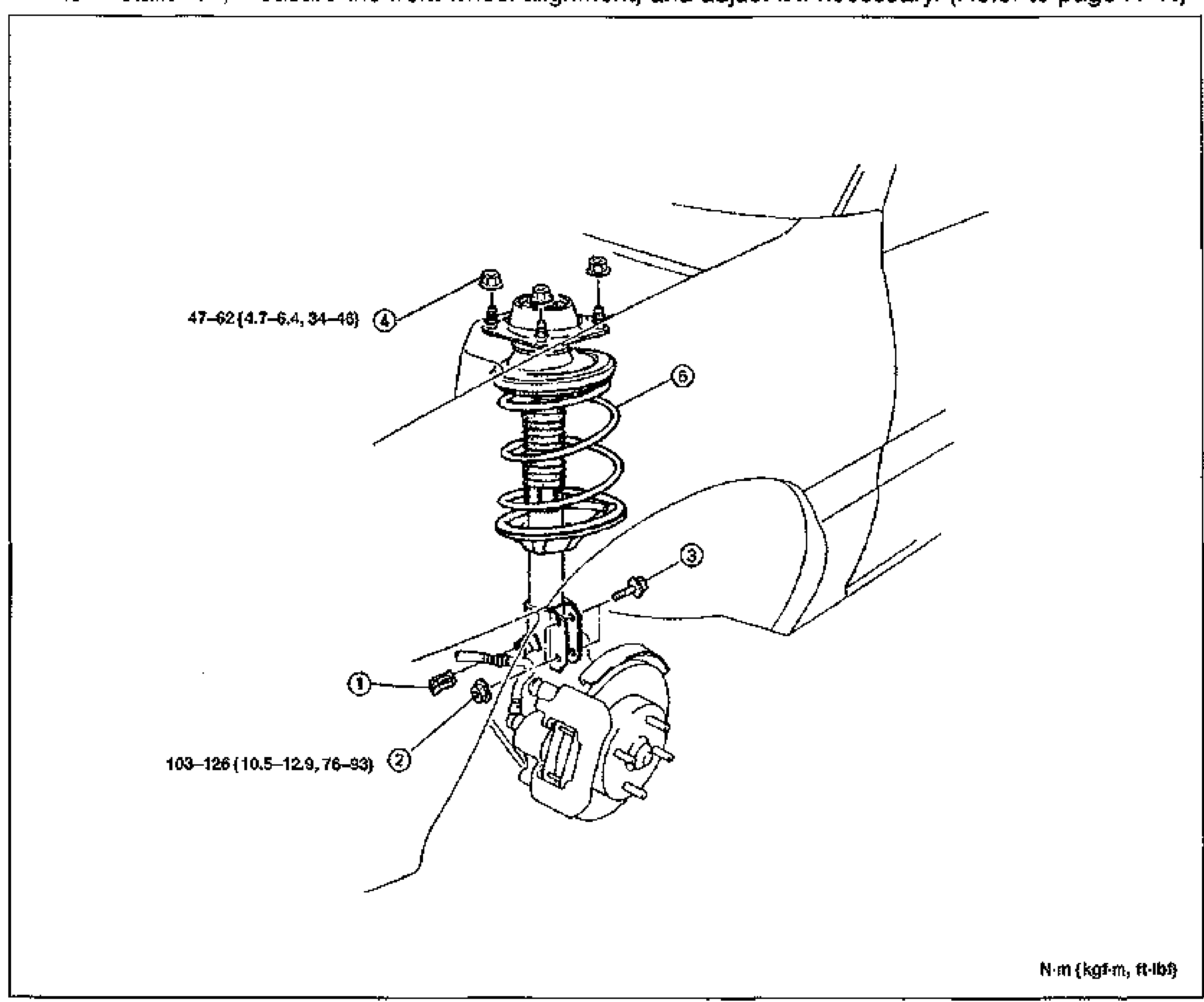
FRONT SUSPENSION (STRUT) - FRONT SHOCK ABSORBER AND SPRING
R-11Exploded view of the front shock absorber and spring assembly mounted at the front strut tower and steering knuckle. Numbered balloon callouts 1-6 identify clip, nuts, bolts and the shock absorber/spring. Tightening-torque tags shown: 47-62 {4.7-6.4, 34-46} at the upper mounting nuts (4), and 103-126 {10.5-12.9, 76-93} at the lower knuckle nuts (2). Torque unit legend bottom-right: N·m {kgf·m, ft·lbf}.
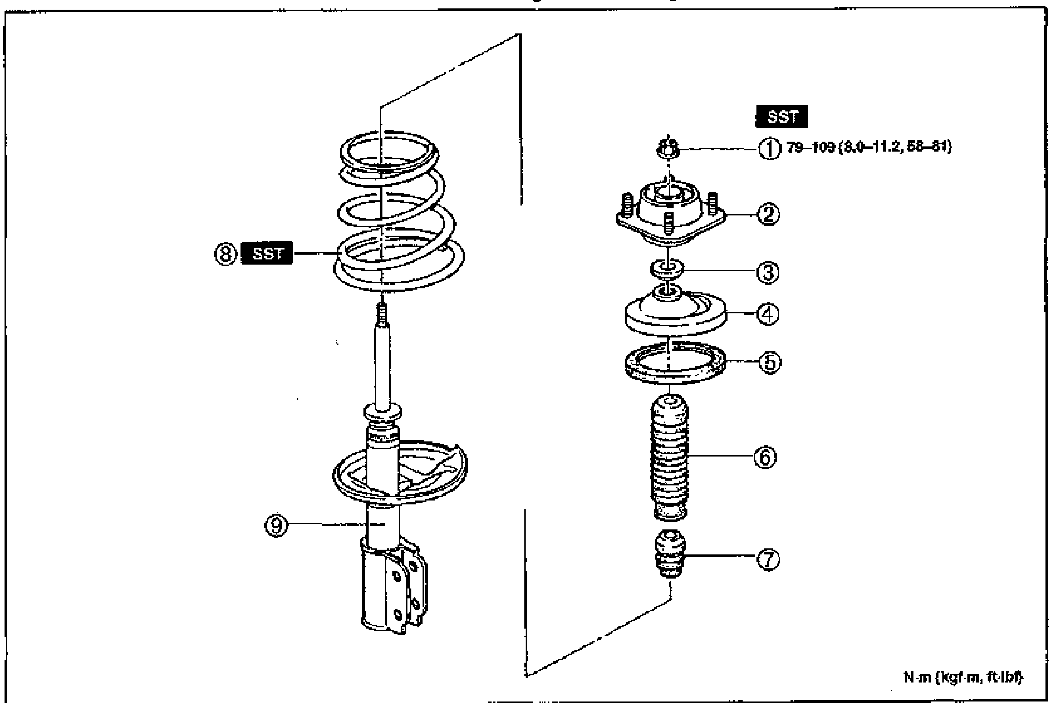
FRONT SUSPENSION (STRUT) - Disassembly / Inspection / Assembly
R-12Exploded view of the front strut (shock absorber and spring) assembly. Left column shows the coil spring (8, SST) over the shock absorber (9). Right column shows, top to bottom: nut (1, SST, torque 79-109 {8.0-11.2, 58-81}), mounting block (2), thrust bearing (3), upper spring seat (4), rubber spring seat (5), dust cover (6) and bound stopper (7). Torque unit legend bottom-right: N·m {kgf·m, ft·lbf}.
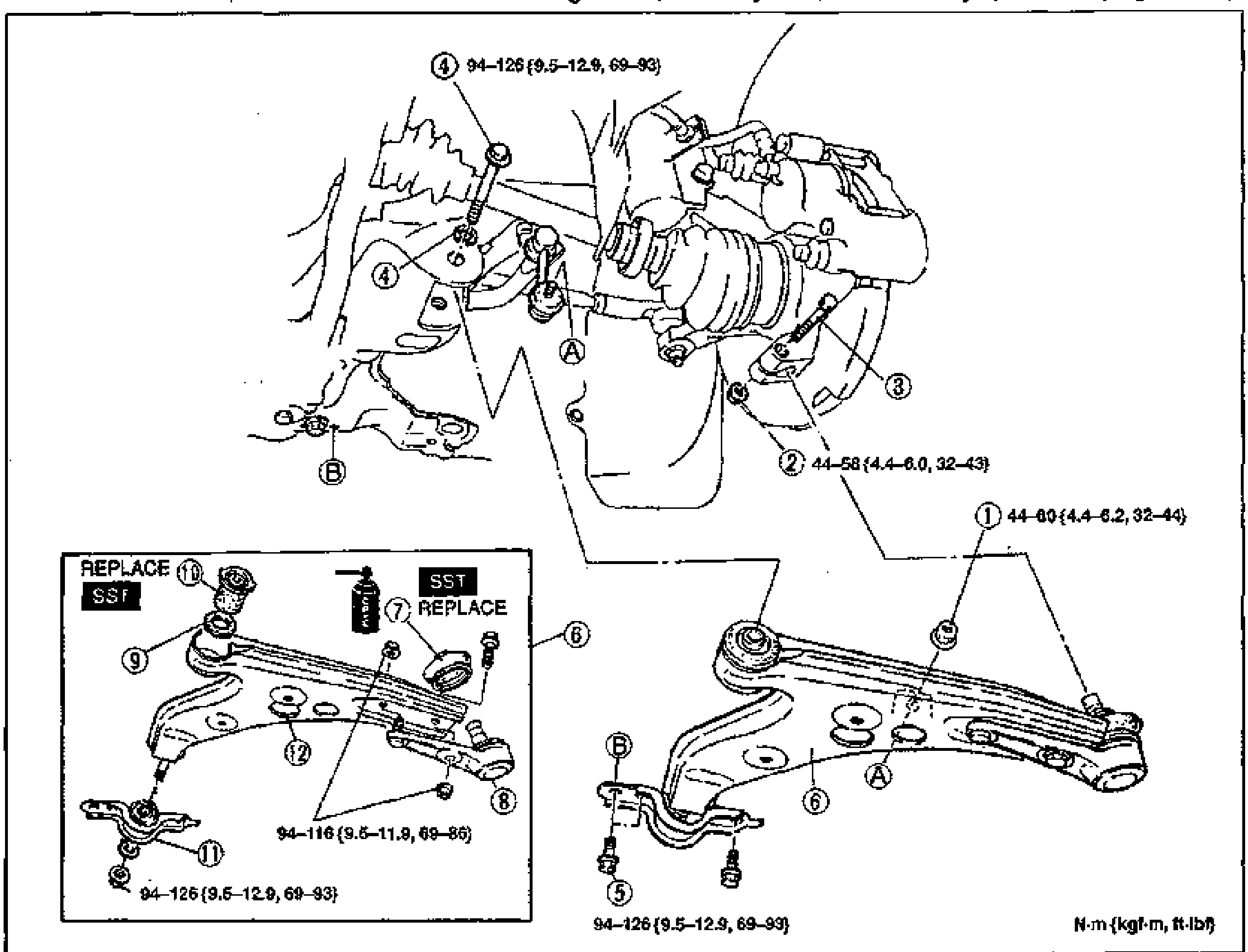
FRONT LOWER ARM — Removal / Inspection / Installation
R-18Exploded view of the front lower arm assembly with numbered balloon callouts (1-12) and tightening-torque tags. Upper portion shows the lower arm mounted to the strut/knuckle and subframe; lower-left inset shows the front lower arm assembly with SST/REPLACE markings on bushings and ball joint; lower-right shows the assembled lower arm. Torque values in N·m {kgf·m, ft·lbf}.
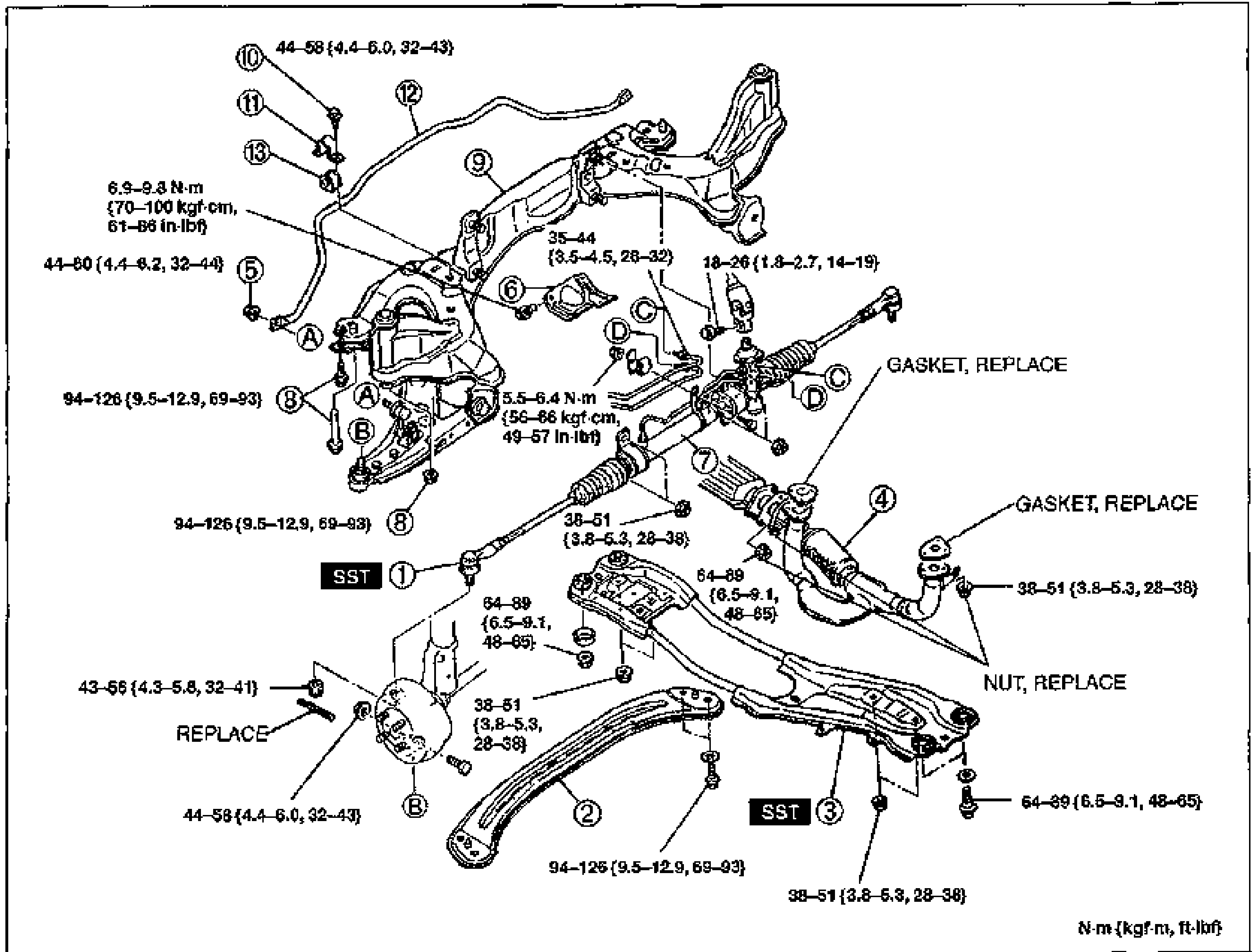
FRONT SUSPENSION (STRUT) — FRONT STABILIZER (K8 DOHC) Removal / Inspection / Installation
R-20Exploded view of the front stabilizer (K8 DOHC) assembly including the lower arm and front crossmember, steering gear and linkage, transverse member, and stabilizer bar/bushings/brackets. Numbered balloon callouts 1-13 with tightening-torque tags in N·m {kgf·m, ft·lbf}. SST markers on items 1 and 3; GASKET/NUT REPLACE notes. Torque values throughout.
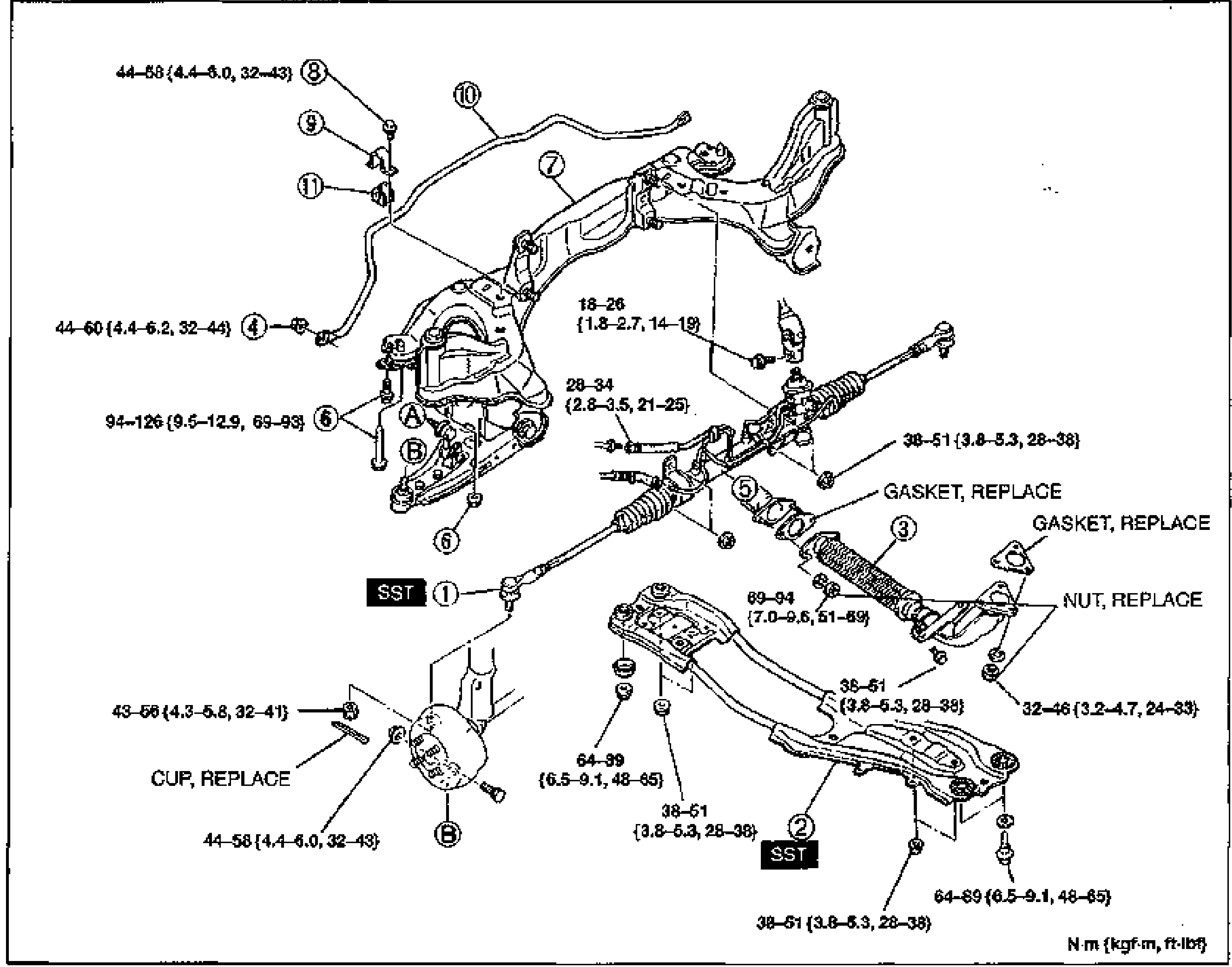
FRONT SUSPENSION (STRUT) — FRONT STABILIZER (B6 DOHC) Removal / Inspection / Installation
R-22Exploded view of the front stabilizer (B6 DOHC) assembly including the lower arm and front crossmember, steering gear and linkage, engine mounting member, and stabilizer bar/bushings/brackets. Numbered balloon callouts 1-11 with tightening-torque tags in N·m {kgf·m, ft·lbf}. SST markers on items 1 and 2; GASKET/NUT/CUP REPLACE notes.
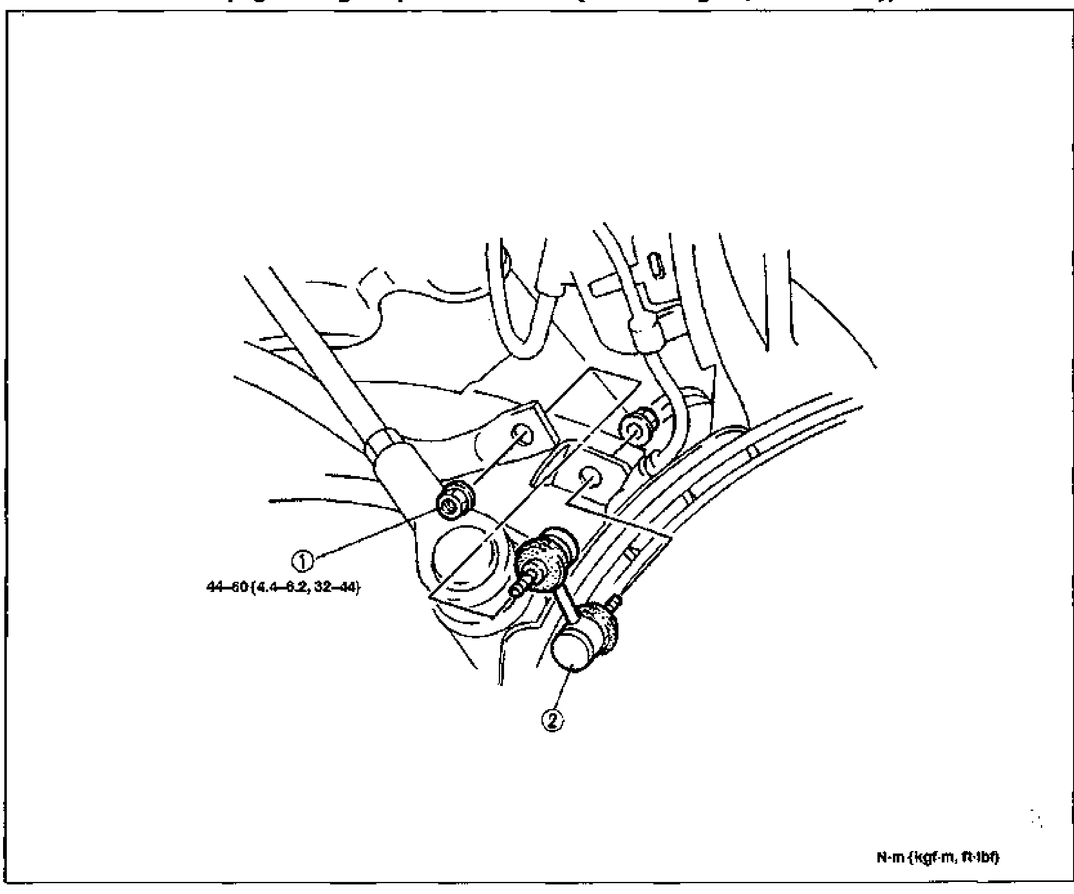
FRONT SUSPENSION (STRUT) — STABILIZER CONTROL LINK Removal / Inspection / Installation
R-24Vehicle underside view showing the stabilizer control link installed between the strut/lower arm and stabilizer bar, with numbered balloon callouts. Callout 1 (Nuts) at the upper mounting with torque tag 44-60 {4.4-6.2, 32-44}; callout 2 (Stabilizer control link) at the lower ball joint stud. Torque in N·m {kgf·m, ft·lbf}.
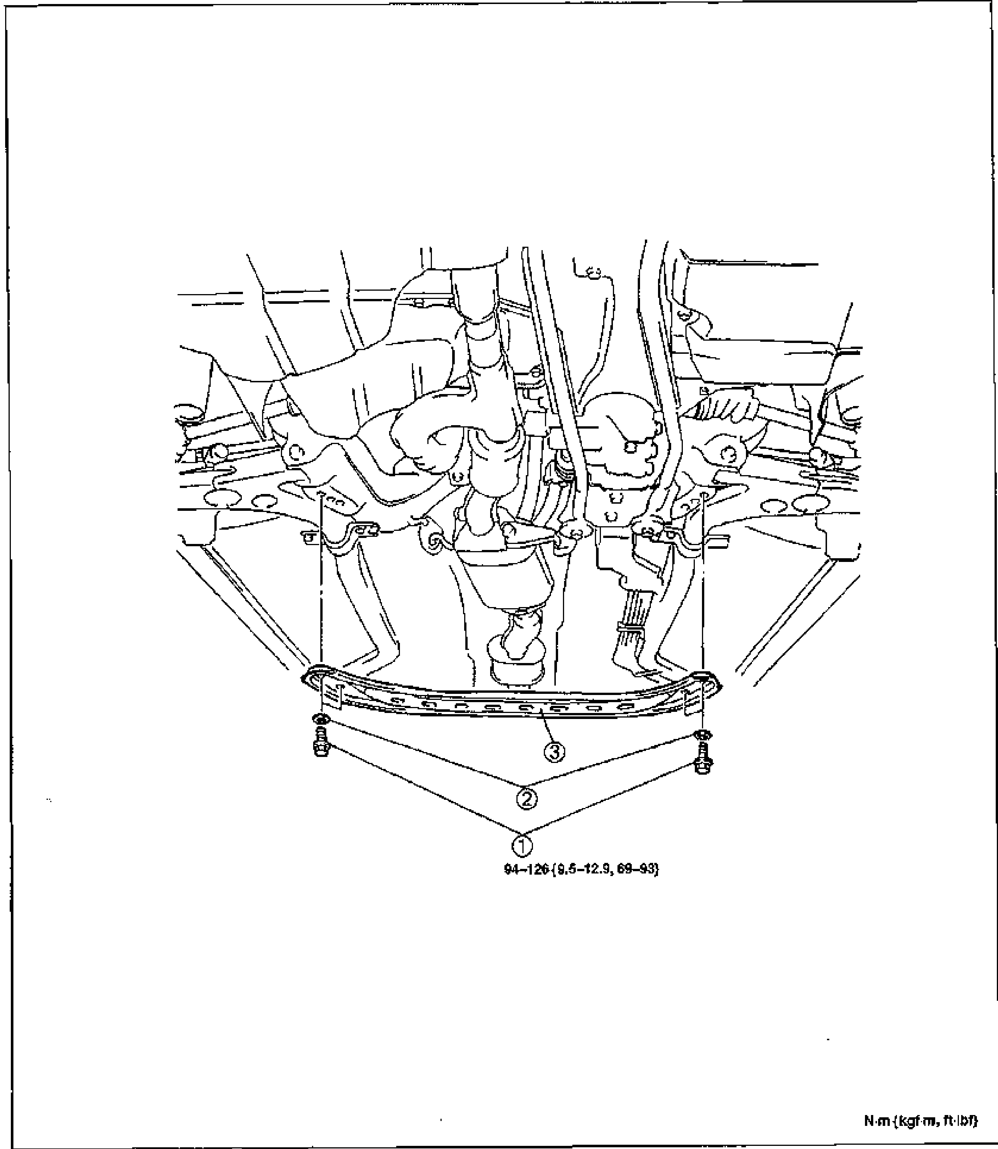
FRONT SUSPENSION (STRUT) — TRANSVERSE MEMBER (K8 DOHC) Removal / Inspection / Installation
R-25Vehicle underside view of the front transverse member bolted across the bottom of the front subframe. Numbered balloon callouts: 1 (Bolts, torque 94-126 {9.5-12.9, 69-93}), 2 (Washers), 3 (Transverse member). Torque in N·m {kgf·m, ft·lbf}.

FRONT SUSPENSION (STRUT) — Front Crossmember parts legend & Removal Note
R-27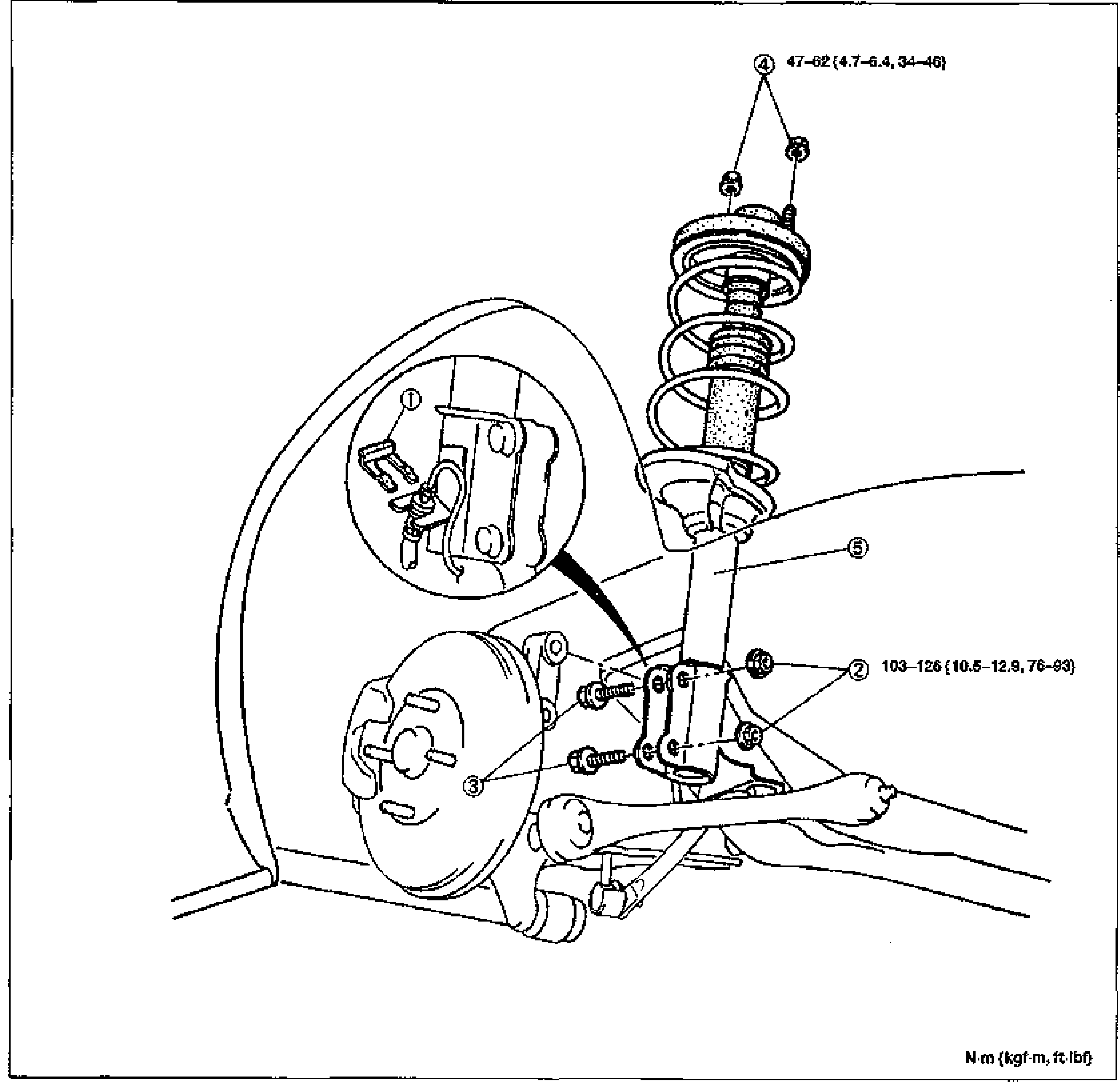
REAR SHOCK ABSORBER AND SPRING — Removal / Installation
R-29Exploded view of the rear shock absorber and coil spring assembly with surrounding rear suspension (knuckle, brake drum/backing plate, lower arm). Numbered balloon callouts 1-5 with tightening torque values. Tightening torques shown: callout 4 nut 47-62 N·m {4.7-6.4 kgf·m, 34-46 ft·lbf}; callout 2 nut 103-126 N·m {10.5-12.9 kgf·m, 76-93 ft·lbf}. Torque legend N·m {kgf·m, ft·lbf} at bottom-right. Inset detail (top-left circle) shows the clip (1).
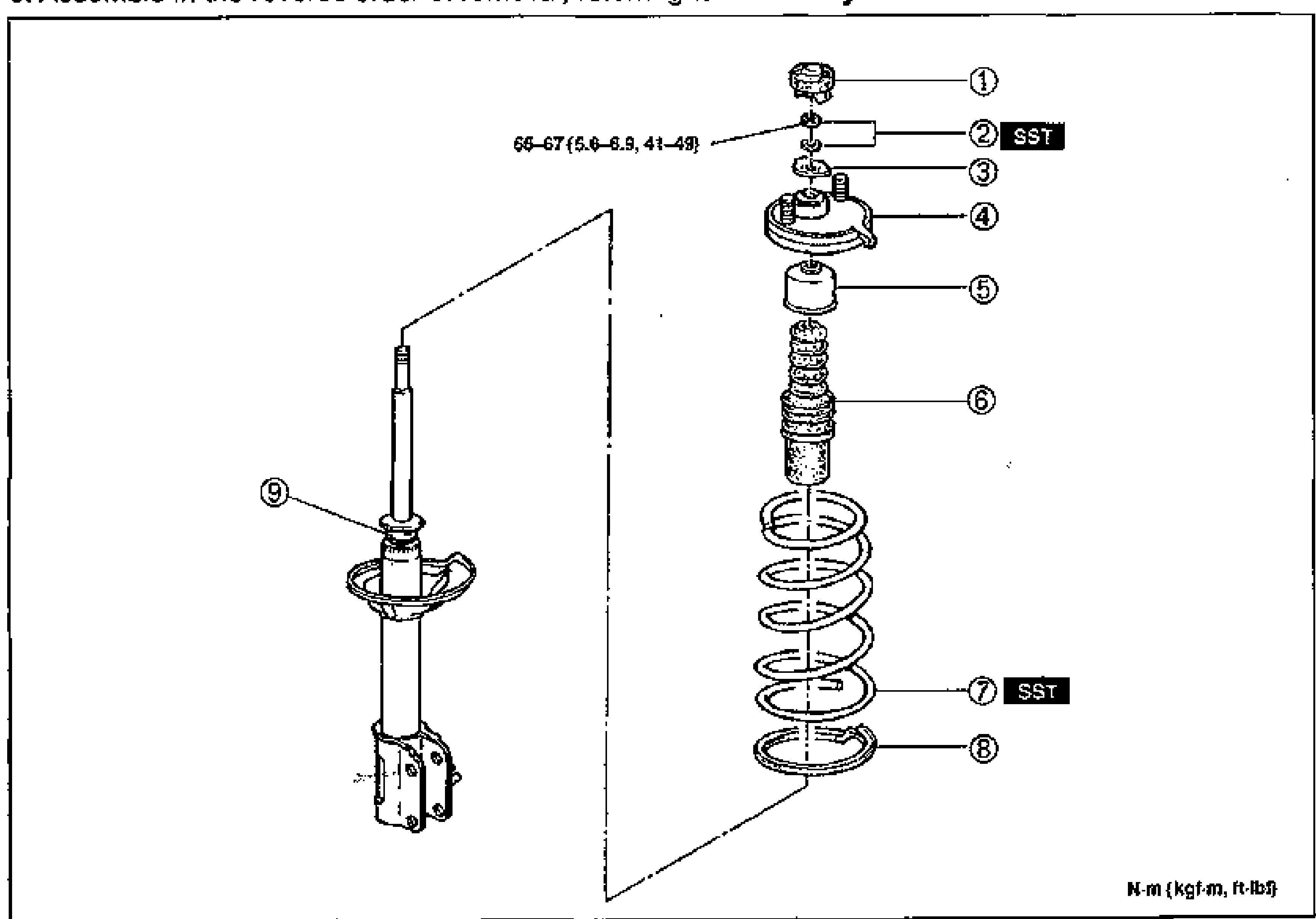
REAR SUSPENSION (STRUT) — Disassembly / Inspection / Assembly
R-30Exploded view of the rear shock absorber (strut) assembly. Left: assembled shock absorber/strut (callout 9). Right: stacked components from top — cap (1), nut and washer (2, marked SST), retainer (3), mounting block (4), stopper seat (5), bound stopper (6), coil spring (7, marked SST), lower spring seat (8). Tightening torque on nut (2): 66-67 N·m {5.6-6.9 kgf·m, 41-49 ft·lbf}. Torque legend N·m {kgf·m, ft·lbf} at bottom-right.
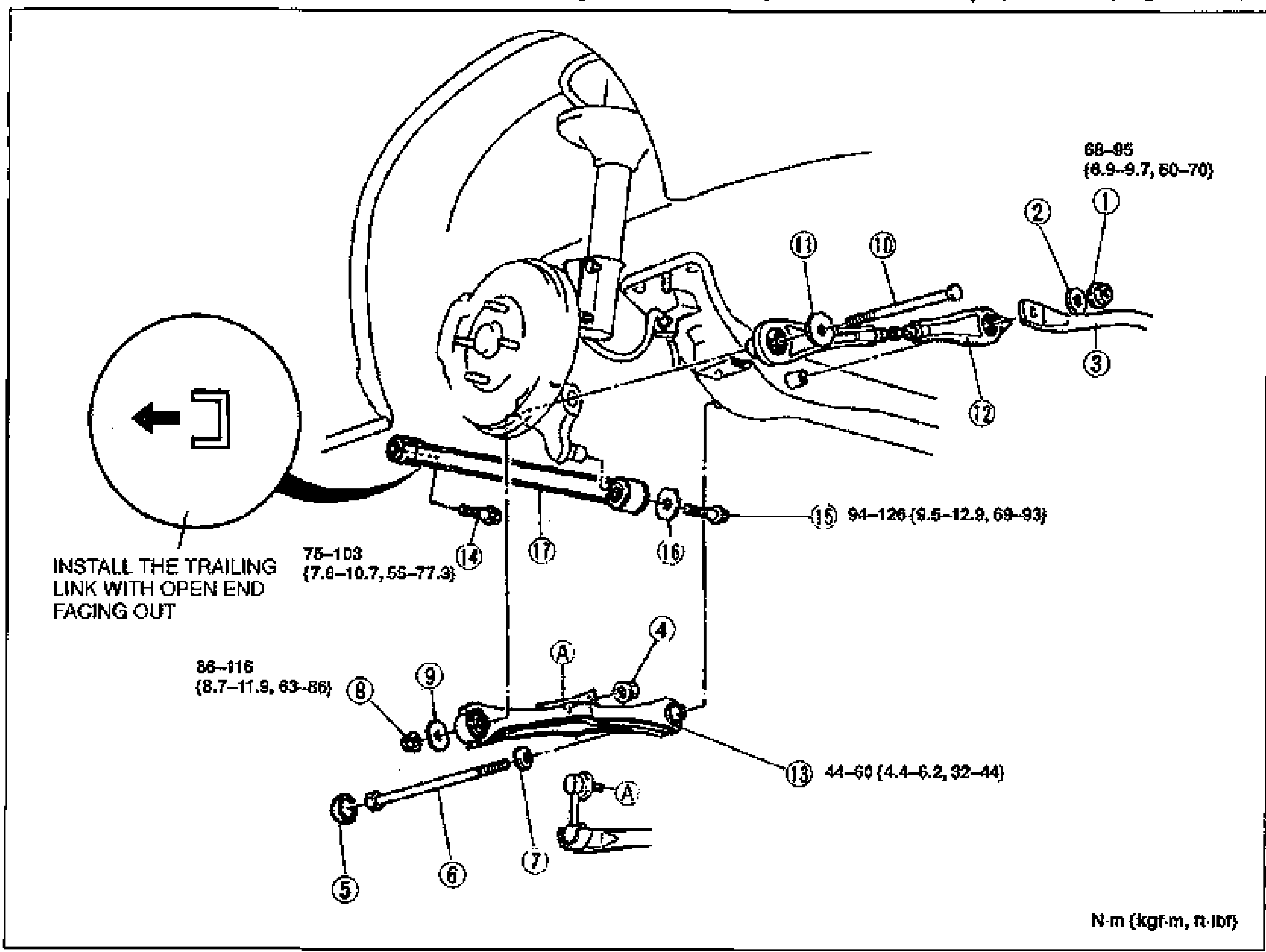
PERFORMANCE ROD, LATERAL LINK AND TRAILING LINK — Removal / Inspection / Installation
R-34Exploded view of the rear performance rod, lateral links (front and rear) and trailing link with the rear knuckle/hub. Numbered balloon callouts 1-17 with torque values. Torque callouts: (1)/(2) 68-95 N·m {6.9-9.7, 60-70}; (15) 94-126 N·m {9.5-12.9, 69-93}; (13) 44-60 N·m {4.4-6.2, 32-44}; (14) 75-103 N·m {7.6-10.7, 55-77.3}; (8) 86-116 N·m {8.7-11.9, 63-86}. Inset (left circle) with arrow: INSTALL THE TRAILING LINK WITH OPEN END FACING OUT. Torque legend N·m {kgf·m, ft·lbf} bottom-right.
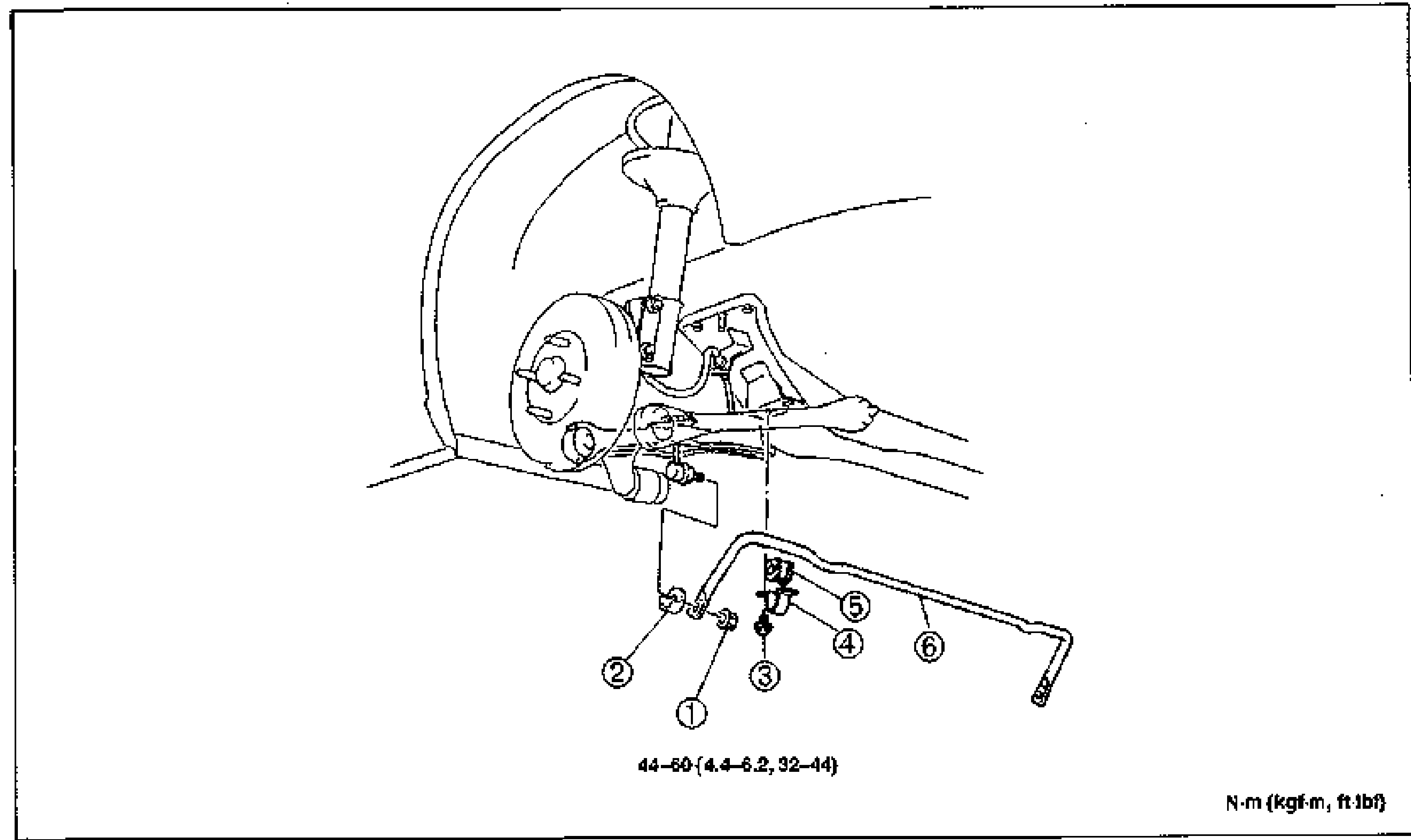
REAR SUSPENSION (STRUT) — Performance rod Installation Note; REAR STABILIZER
R-35Exploded view of the rear stabilizer (sway bar) and its mounting at the rear knuckle/hub. Numbered balloon callouts 1-6: nuts, protectors, bolts, stabilizer brackets, stabilizer bushings, stabilizer bar. Torque callout 44-60 N·m {4.4-6.2, 32-44}. Torque legend N·m {kgf·m, ft·lbf} bottom-right.
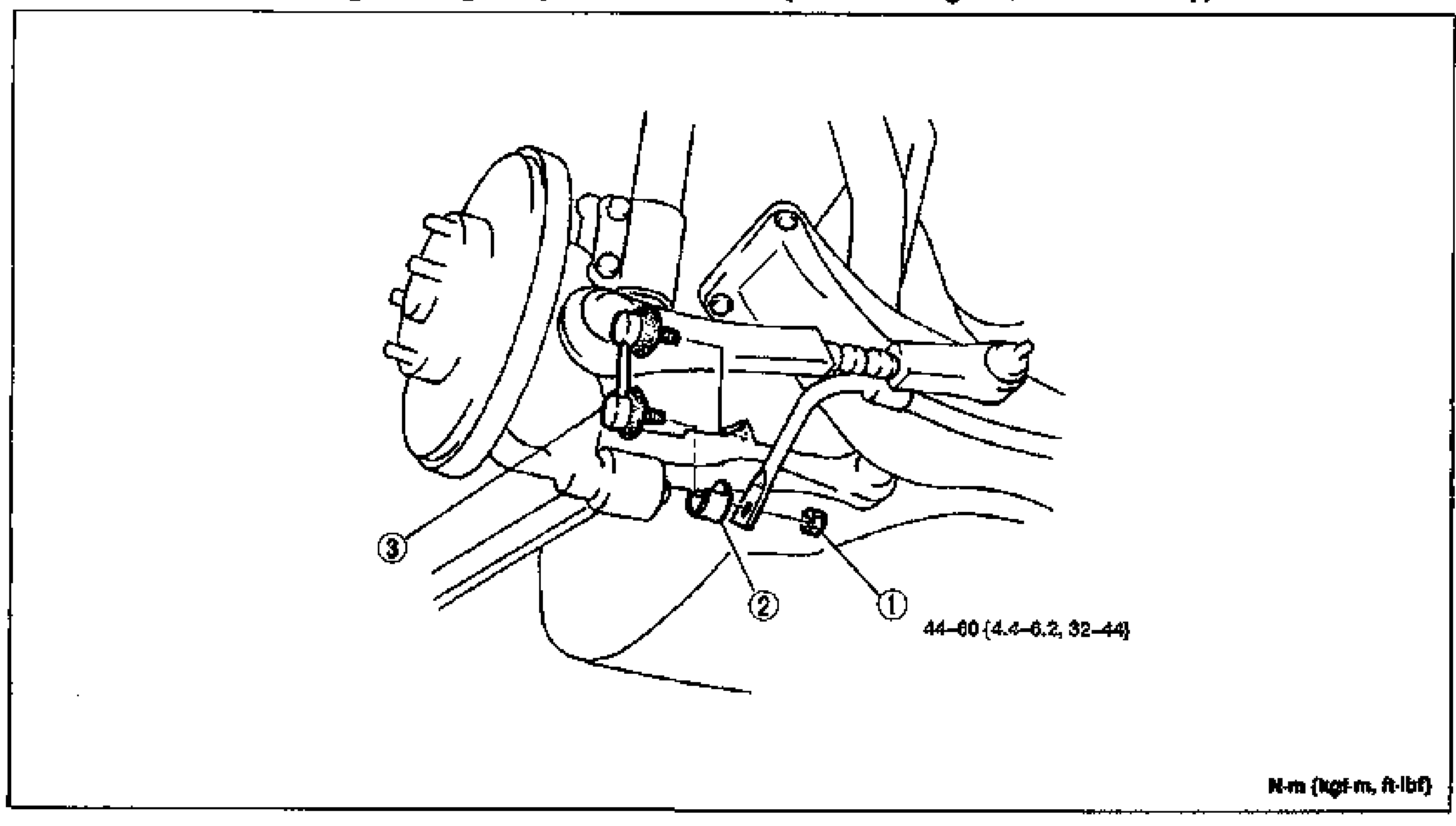
REAR SUSPENSION (STRUT) — Stabilizer bushing Installation Note; STABILIZER CONTROL LINK
R-36Exploded view of the rear stabilizer control link and its mounting at the rear knuckle/hub. Numbered balloon callouts 1-3: nuts, protector, stabilizer control link. Torque callout 44-60 N·m {4.4-6.2, 32-44}. Torque legend N·m {kgf·m, ft·lbf} bottom-right.
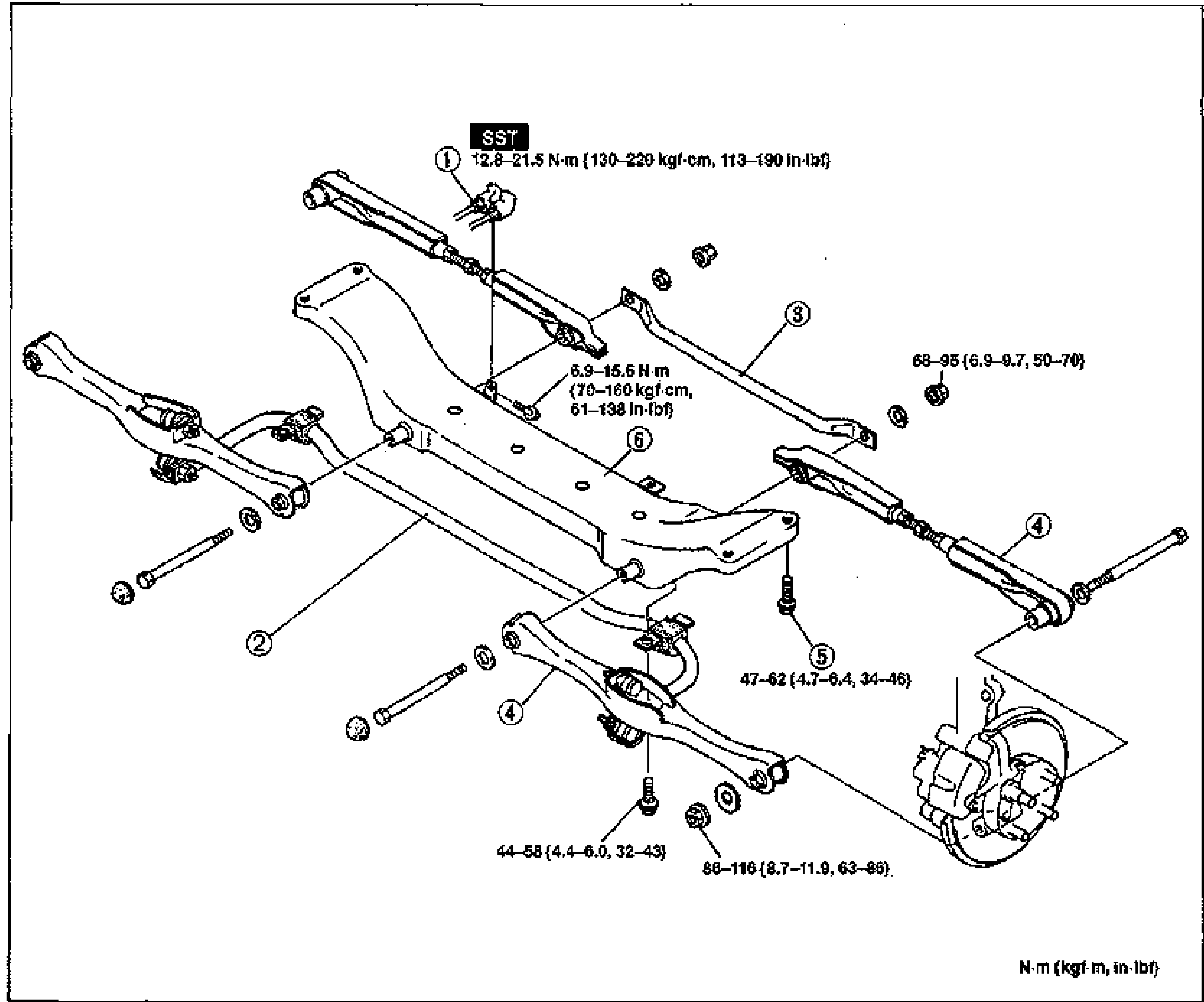
REAR CROSSMEMBER — Removal / Inspection / Installation
R-37Exploded view of the rear crossmember assembly with attached lateral links (front and rear), performance rod, rear stabilizer, brake pipe and rear hub/knuckle. Numbered balloon callouts 1-6 with torque values. Torque callouts: (1) brake pipe (SST) 12.8-21.5 N·m {130-220 kgf·cm, 113-190 in·lbf}; 6.9-15.6 N·m {70-160 kgf·cm, 61-138 in·lbf}; (3) 68-95 N·m {6.9-9.7, 50-70}; (5) 47-62 N·m {4.7-6.4, 34-46}; (4) 44-58 N·m {4.4-6.0, 32-43}; 86-116 N·m {8.7-11.9, 63-86}. Torque legend N·m {kgf·m, in·lbf} bottom-right.
Body
S40 diagrams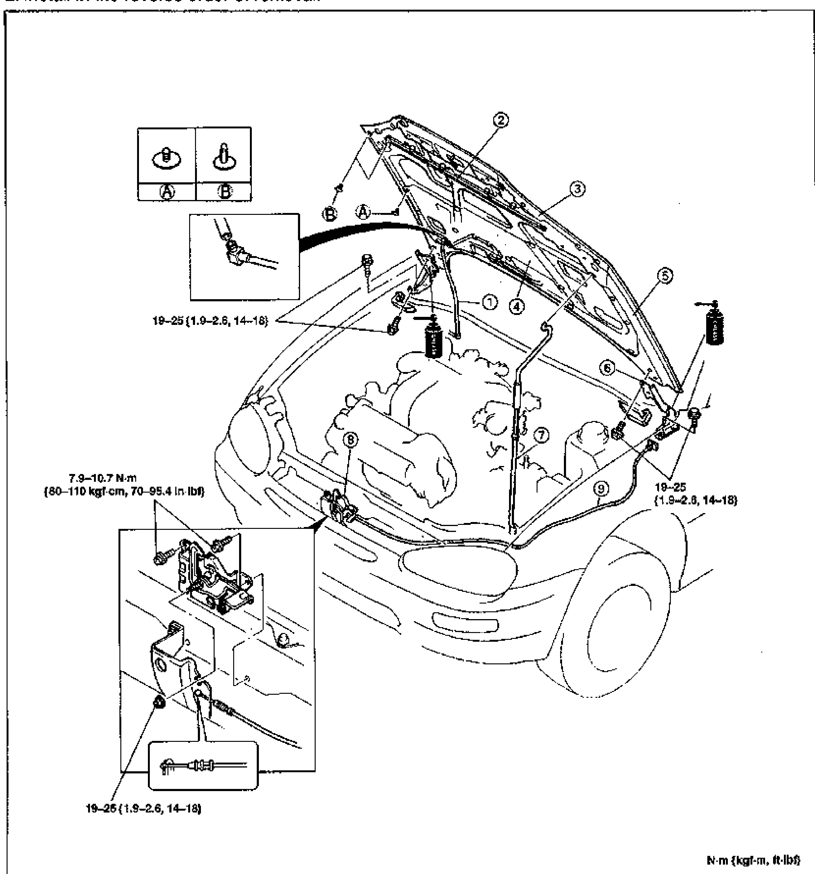
HOOD
S-5Exploded view of the hood and engine-bay front structure with the hood raised, showing 9 numbered balloon callouts: windshield washer pipe, surround seal weatherstrip, hood deflector, hood insulator, hood, hood hinge, hood stay, hood lock, and hood release cable. Inset detail boxes show clip types A and B, a washer-pipe connector, and the hood lock/release cable assembly. Torque values 19–25 N·m and 7.9–10.7 N·m are called out at fastener points.
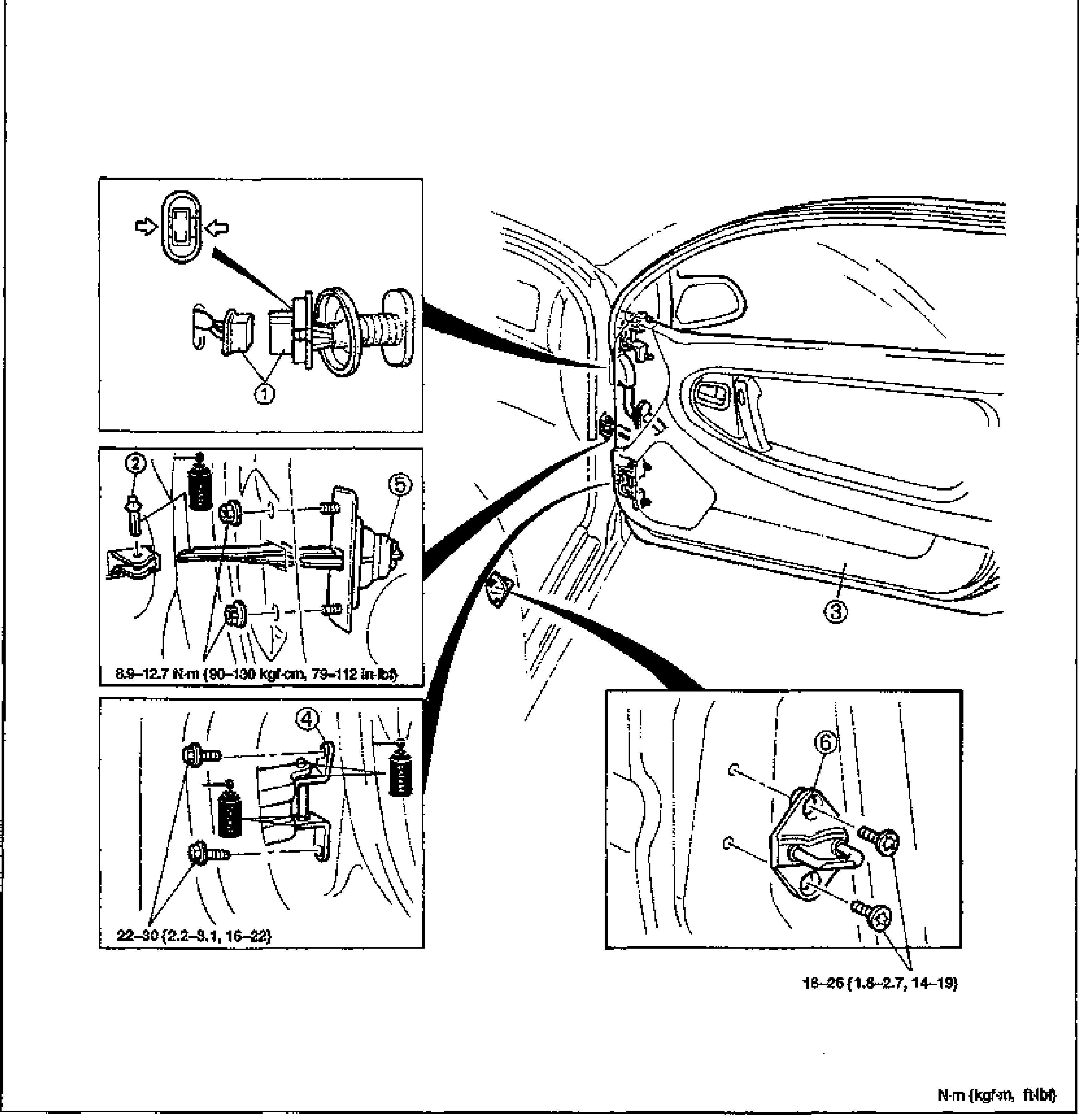
DOOR
S-8Exploded view of the door assembly and its mounting points, with inset detail boxes showing 6 numbered balloon callouts: harness connector, checker pin, door (main panel), door hinge, checker, and door lock striker. Torque values 8.9–12.7 N·m, 22–30, and 18–26 are called out at the respective fastener insets.
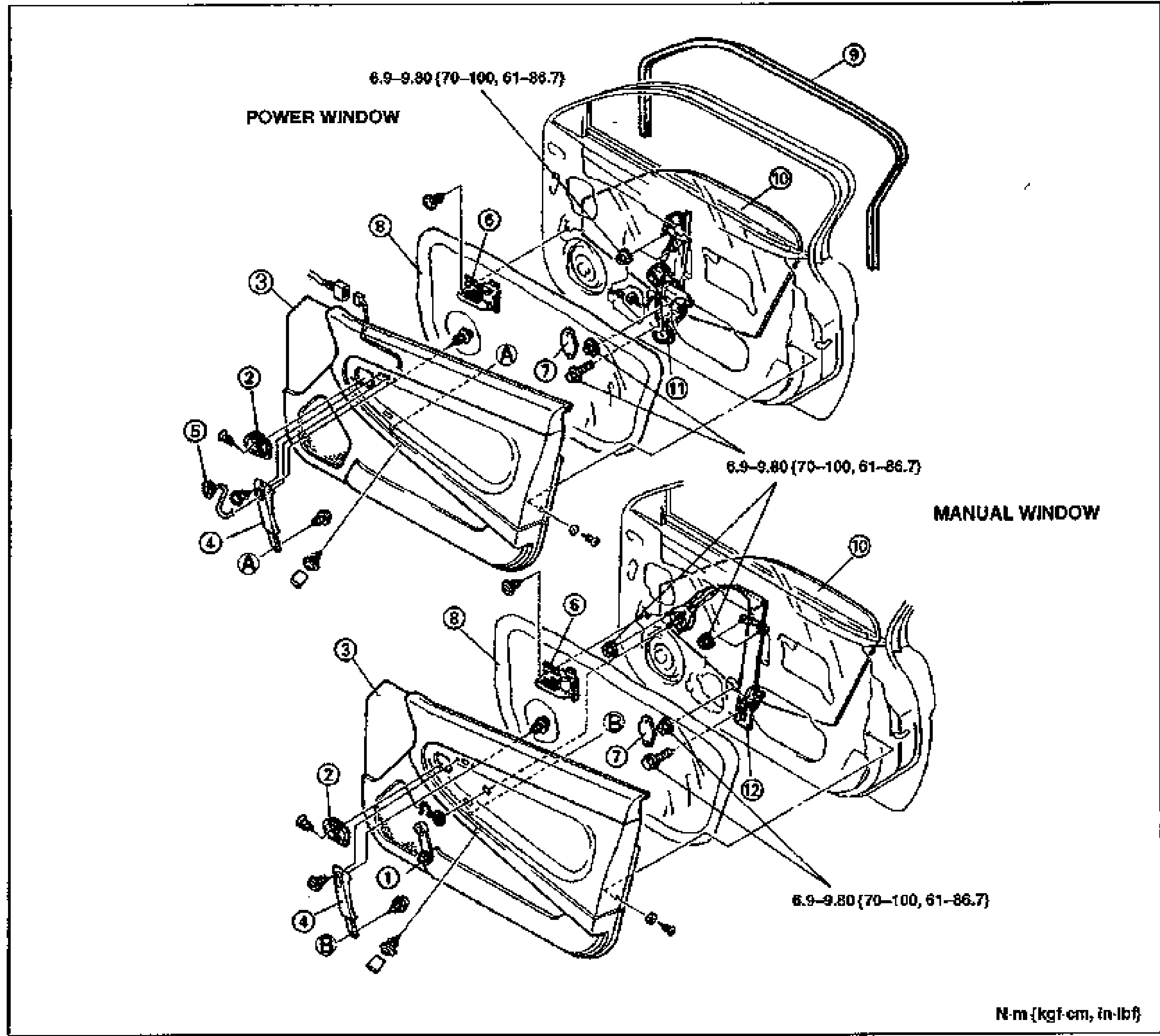
WINDOW REGULATOR AND GLASS
S-10Exploded view of the door window regulator and glass assembly, shown in two variants: POWER WINDOW (upper) and MANUAL WINDOW (lower). Each shows the door panel, door trim, inner handle cover, pull handle, glass run channel, door glass and window regulator with numbered balloon callouts 1-12. Torque values 6.9-9.80 N·m {70-100 kgf-cm, 61-86.7 in-lbf} are called out at bolt locations. Units note at bottom right: N·m {kgf-cm, in-lbf}.
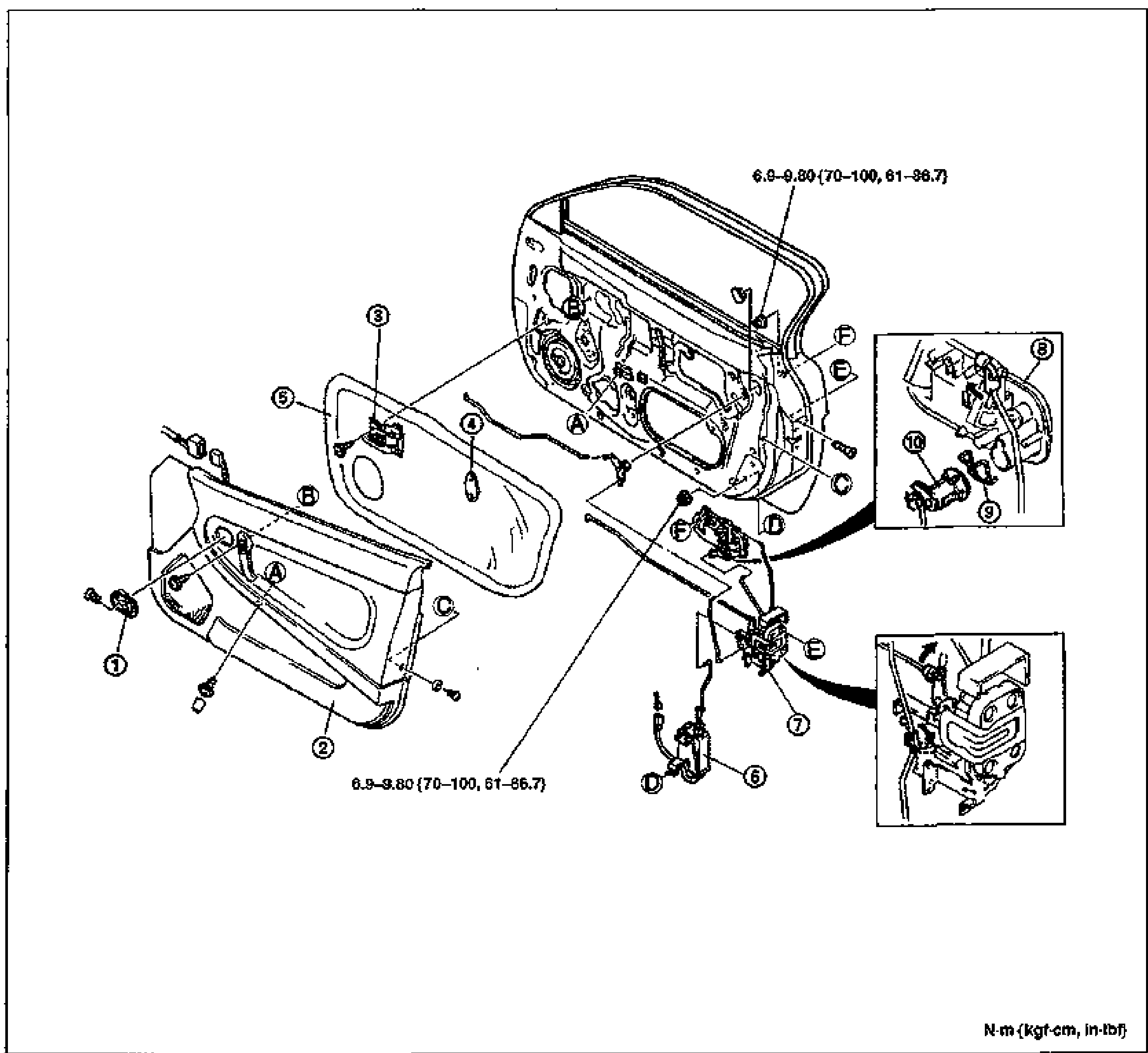
DOOR LOCK AND OPENER
S-12Exploded view of the door lock and opener assembly: door panel, door trim, inner handle cover, door screen, sealing pad, door lock, door lock actuator, outer handle, lock cylinder and lock cylinder retainer. Numbered balloon callouts 1-10 plus letter callouts A-F mark fastener/connection points. Two detail insets at right show the outer handle/lock cylinder area and the door lock mechanism. Torque value 6.9-9.80 N·m {70-100 kgf-cm, 61-86.7 in-lbf} called out at bolt locations. Units note at bottom right: N·m {kgf-cm, in-lbf}.
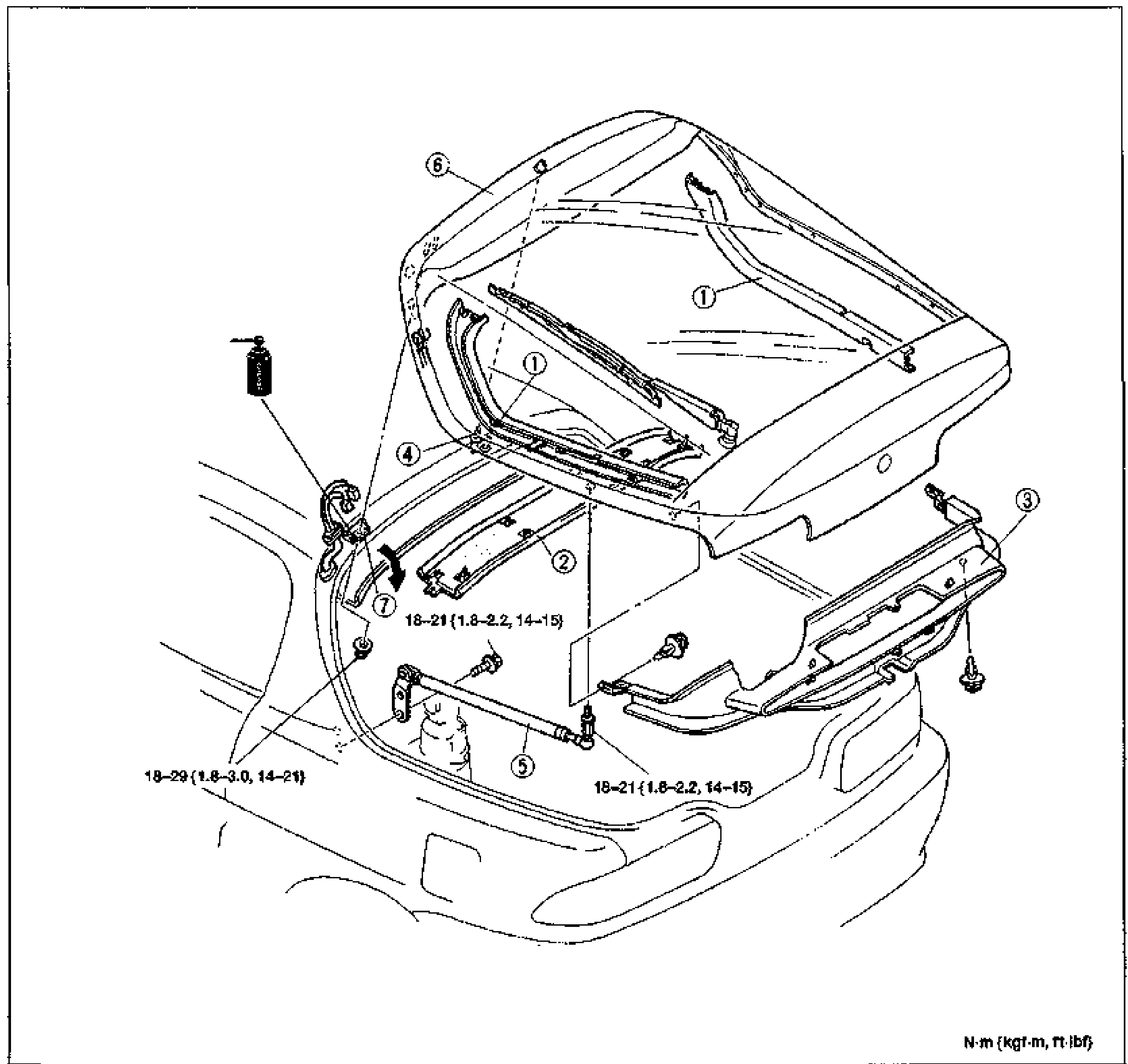
LIFTGATE
S-13Exploded view of the liftgate (rear hatch) assembly shown opened on the rear of the vehicle. Numbered balloon callouts 1-7 mark the liftgate side trim, upper trim, lower trim, rear washer pipe, stay damper, liftgate panel and liftgate hinge. Torque values are called out: 18-21 N·m {1.8-2.2 kgf-m, 14-15 ft-lbf} at the hinge bolts and 18-29 N·m {1.8-3.0 kgf-m, 14-21 ft-lbf} at another fastener. Units note at bottom right: N·m {kgf-m, ft-lbf}.
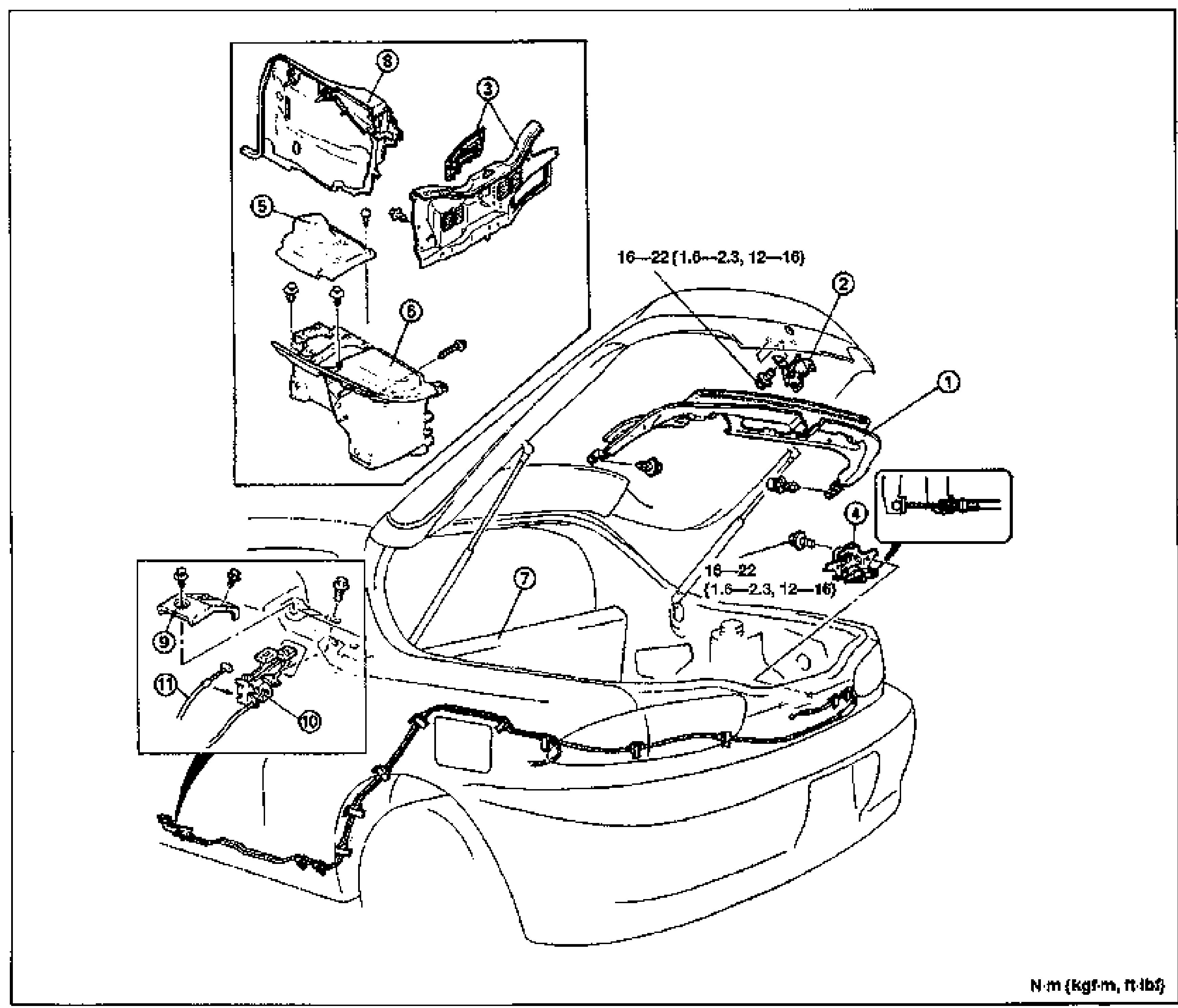
LIFTGATE LOCK AND OPENER
S-15Exploded view of the liftgate lock and opener system on the rear of the vehicle. Numbered balloon callouts 1-11 mark the liftgate lower trim, liftgate striker, trunk end trim, liftgate lock, rear speaker cover, trunk side trim, rear seat, quarter trim, opener bezel, opener lever and liftgate opener cable. Detail insets at top-left and bottom-left show trim panels and the opener lever/cable assembly; an inset at right shows the striker detail. Torque value 16-22 N·m {1.6-2.3 kgf-m, 12-16 ft-lbf} called out at the lock and striker bolts. Units note at bottom right: N·m {kgf-m, ft-lbf}.
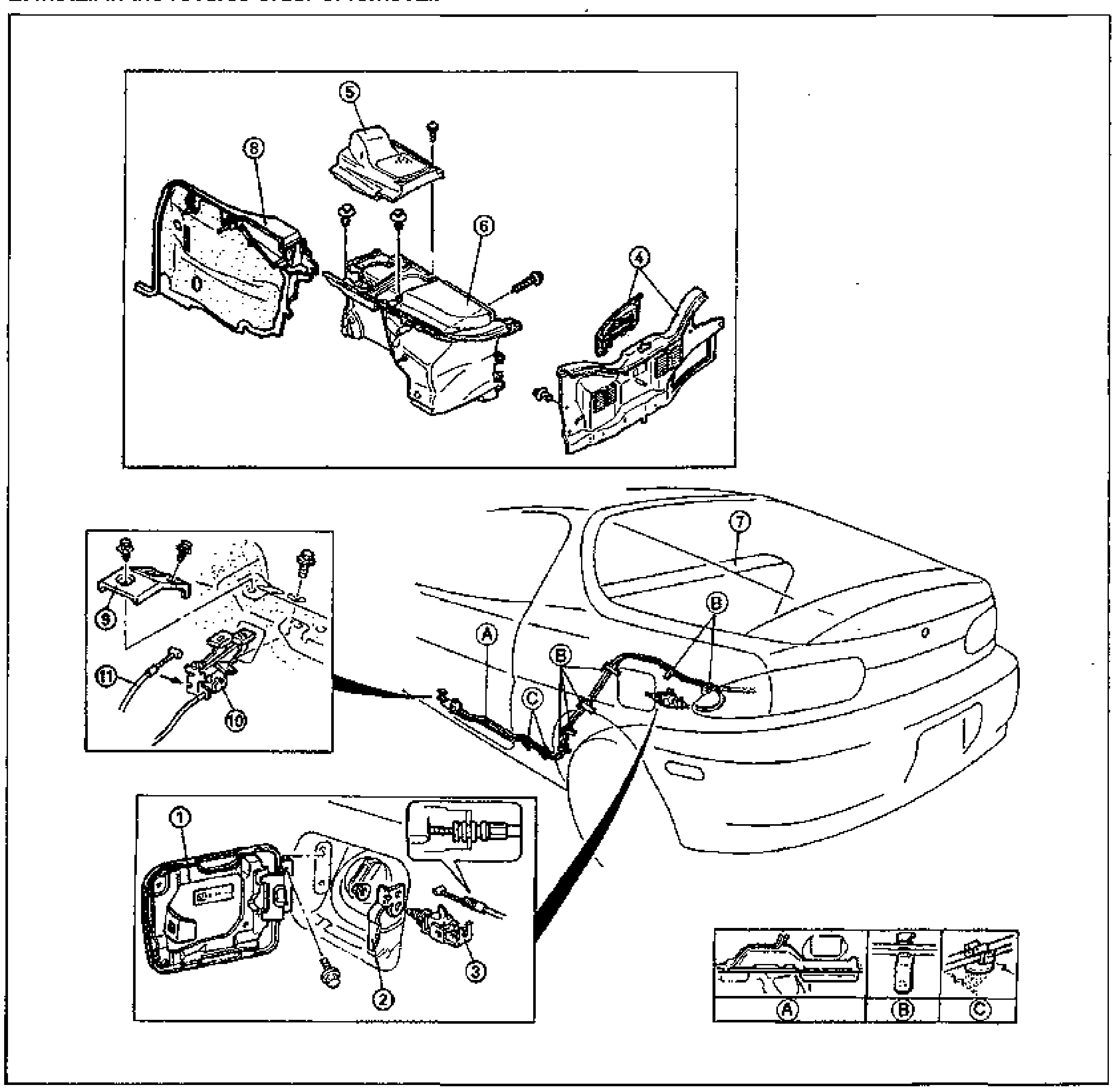
FUEL-FILLER LID AND OPENER
S-16Exploded view of the fuel-filler lid and opener system at the rear of the vehicle. Numbered balloon callouts 1-11 mark the fuel-filler lid, lift spring, fuel-filler lid opener, trunk end trim, rear speaker cover, trunk side trim, rear seat, quarter trim, opener bezel, opener lever and fuel-filler lid opener cable. Detail insets show: top-left trim panels, middle-left opener lever/cable assembly, bottom-left fuel-filler lid opener detail. Letter callouts A, B, C mark cable routing points, expanded in a three-cell legend strip at bottom right (A, B, C).
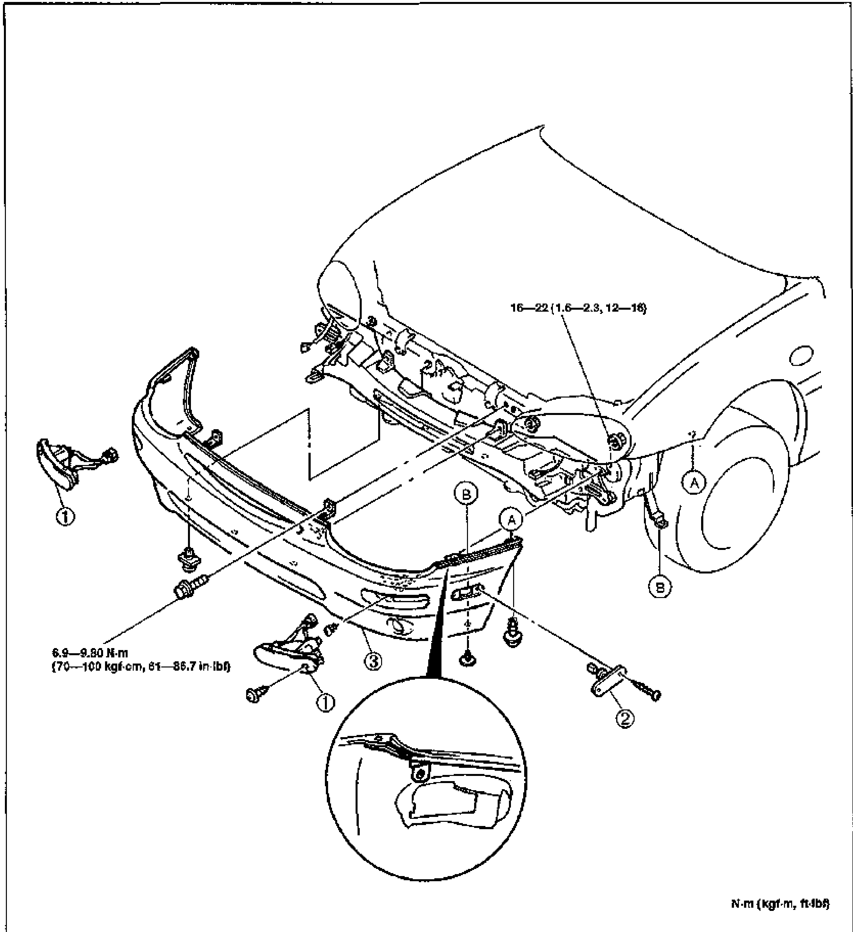
FRONT BUMPER
S-17Exploded view of the front bumper assembly on the front of the vehicle (hood/fender shown). Numbered balloon callouts 1-3 mark the front combination light, front side marker light and front bumper. Letter callouts A and B mark fastener locations. A circular detail inset at bottom shows a bumper bracket clip. Torque values: 16-22 N·m {1.6-2.3 kgf-m, 12-16 ft-lbf} at bracket bolts and 6.9-9.80 N·m {70-100 kgf-cm, 61-86.7 in-lbf} at the light mounting bolts. Units note at bottom right: N·m {kgf-m, ft-lbf}.
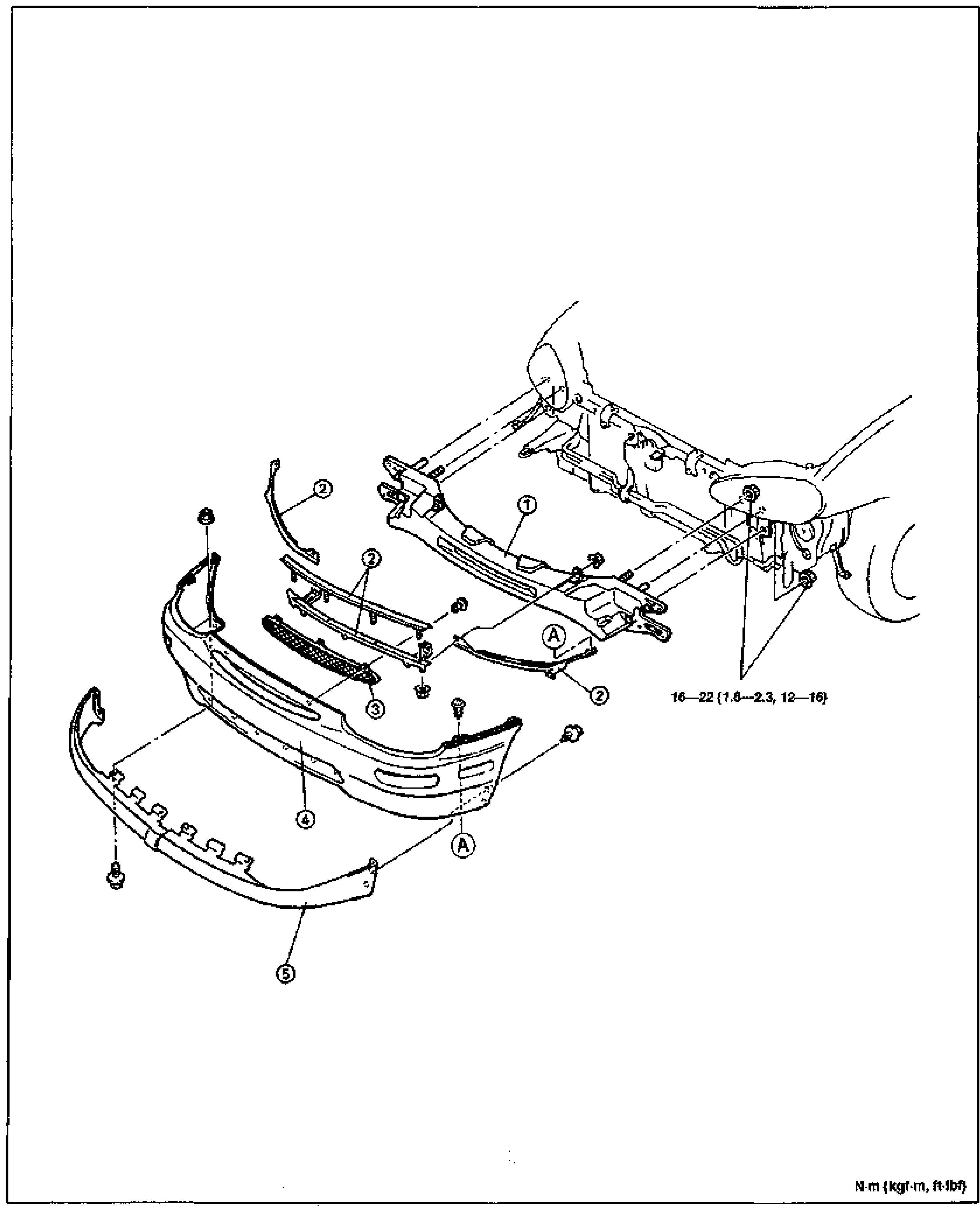
FRONT BUMPER
S-18Exploded view of the front bumper disassembly. Numbered balloon callouts 1-5 mark the front bumper reinforcement, set plate, center mesh, front bumper fascia and front air dam. Letter callout A marks fastener/clip locations. Torque value 16-22 N·m {1.6-2.3 kgf-m, 12-16 ft-lbf} called out at the reinforcement mounting bolts. Units note at bottom right: N·m {kgf-m, ft-lbf}.
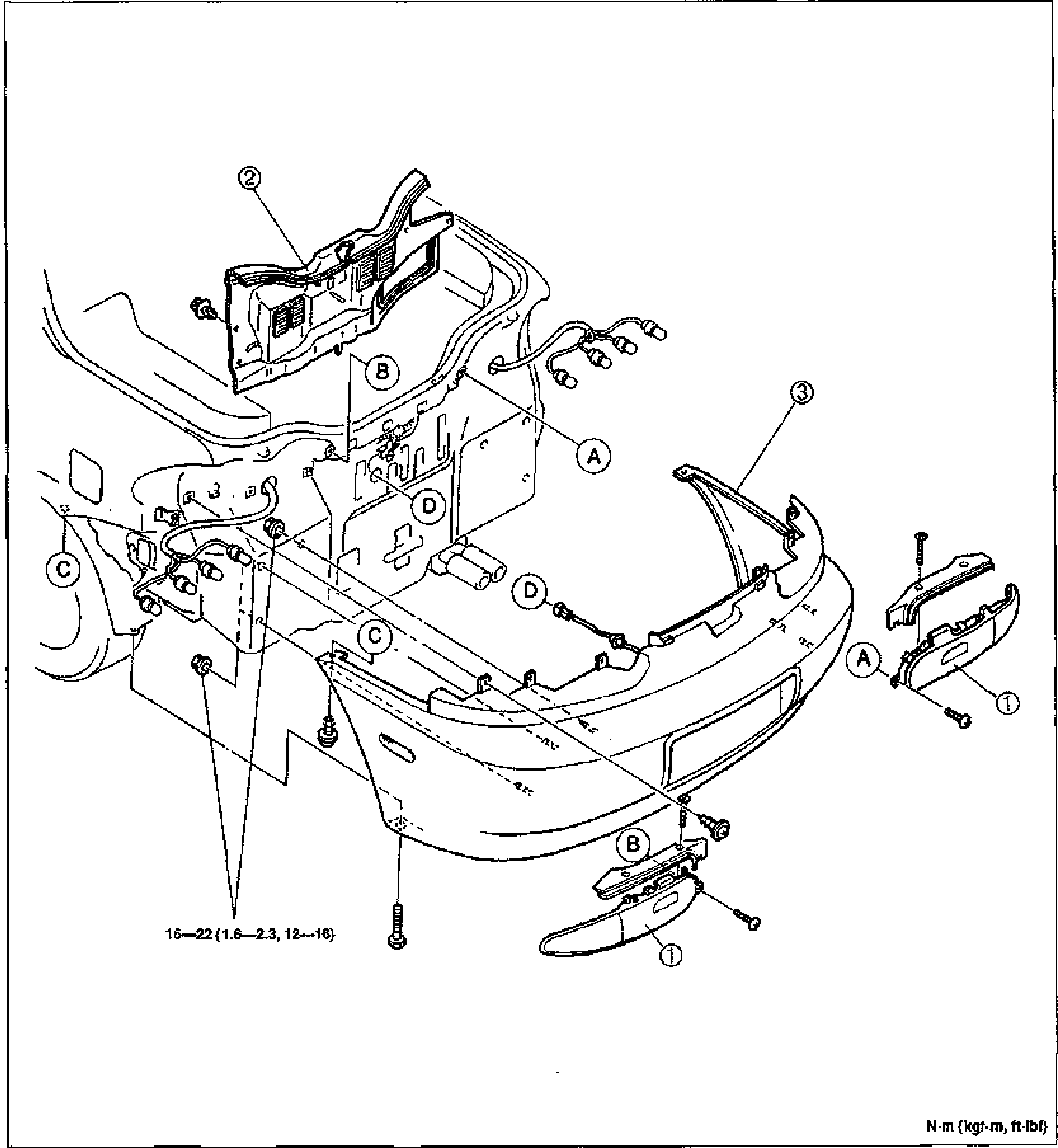
REAR BUMPER
S-19Exploded view of the rear bumper assembly on the rear of the vehicle. Numbered balloon callouts 1-3 mark the rear combination light, trunk end trim and rear bumper. Letter callouts A, B, C, D mark fastener and clip attachment points around the bumper and rear body. Torque value 16-22 N·m {1.6-2.3 kgf-m, 12-16 ft-lbf} called out at bumper mounting bolts. Units note at bottom right: N·m {kgf-m, ft-lbf}.
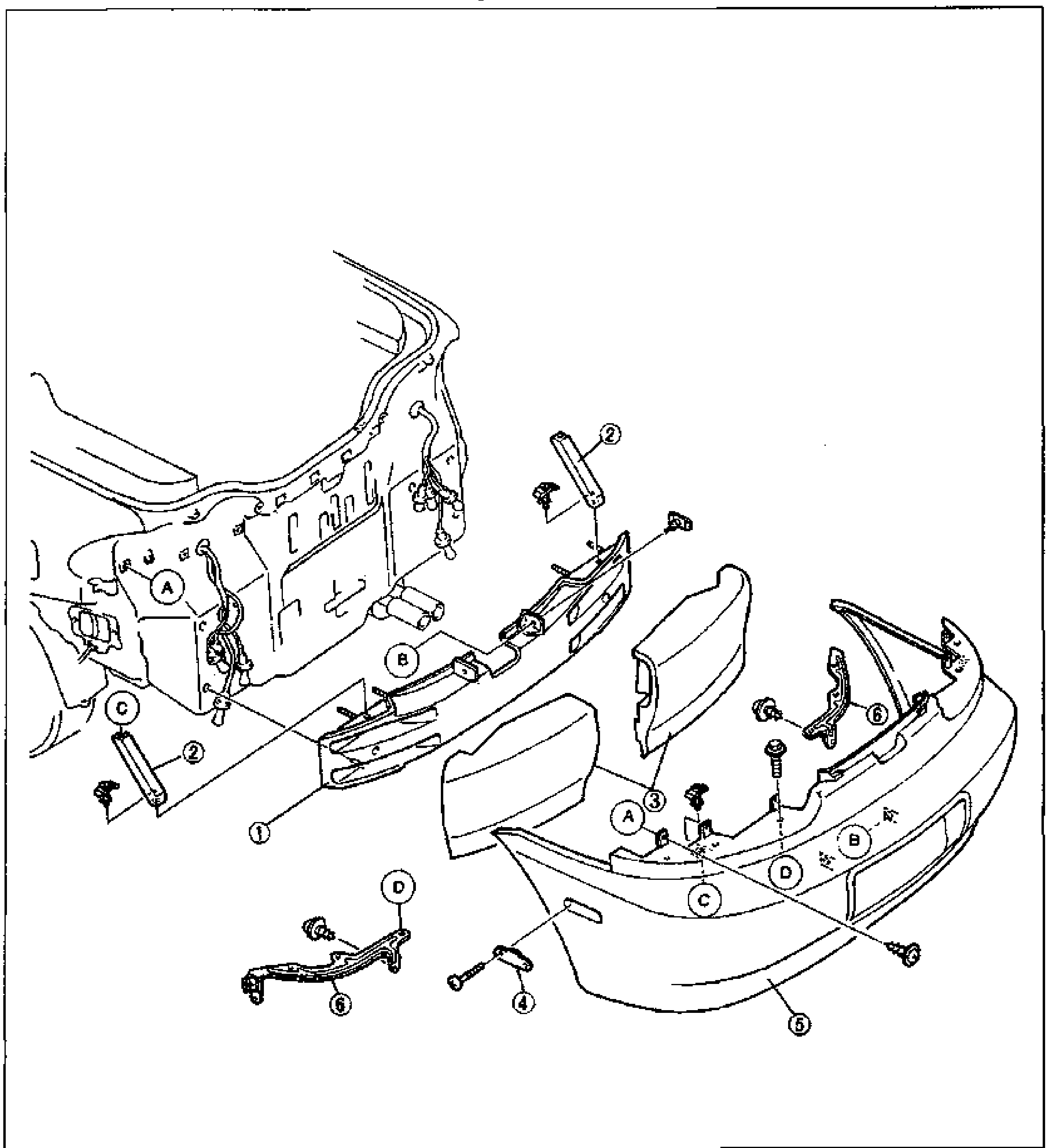
Rear Bumper
S-20Exploded view of the rear bumper assembly. Shows the rear body panel at left and the rear bumper fascia at right, with components separated and numbered balloons 1-6: rear bumper reinforcement, rear bumper bracket (x2), energy-absorbing foam, rear side marker light, rear bumper fascia, and rear bumper retainer. Letter callouts A-D mark attachment/fastener points. Bolts and clips are shown exploded along their mounting axes.
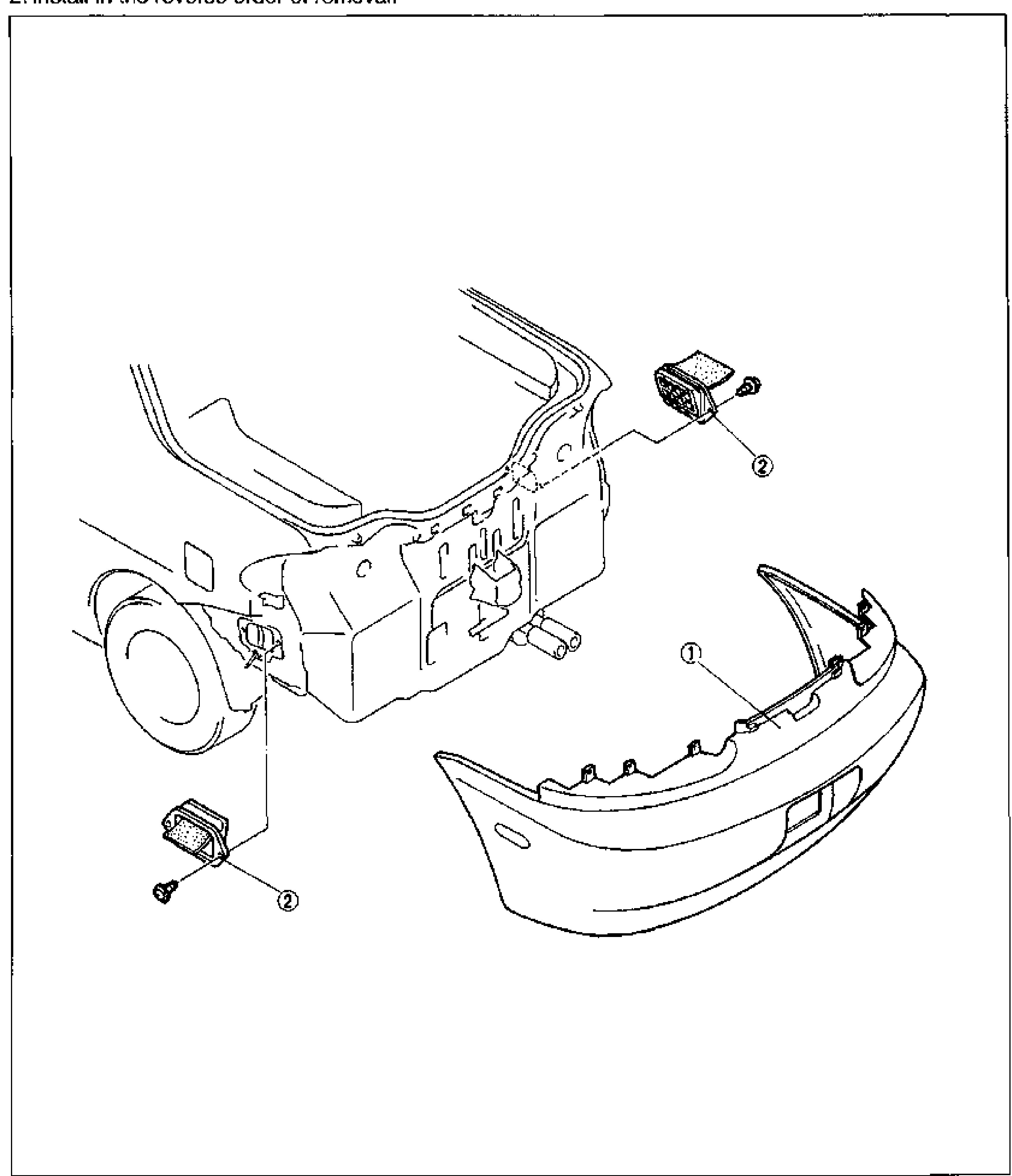
Extractor Chamber
S-21Exploded view of the extractor chamber components at the rear of the vehicle. Shows the rear body/quarter panel area with the rear bumper (1) separated at right, and two extractor chambers (2) shown removed with their retaining clips/bolts, one at upper area and one at lower left.
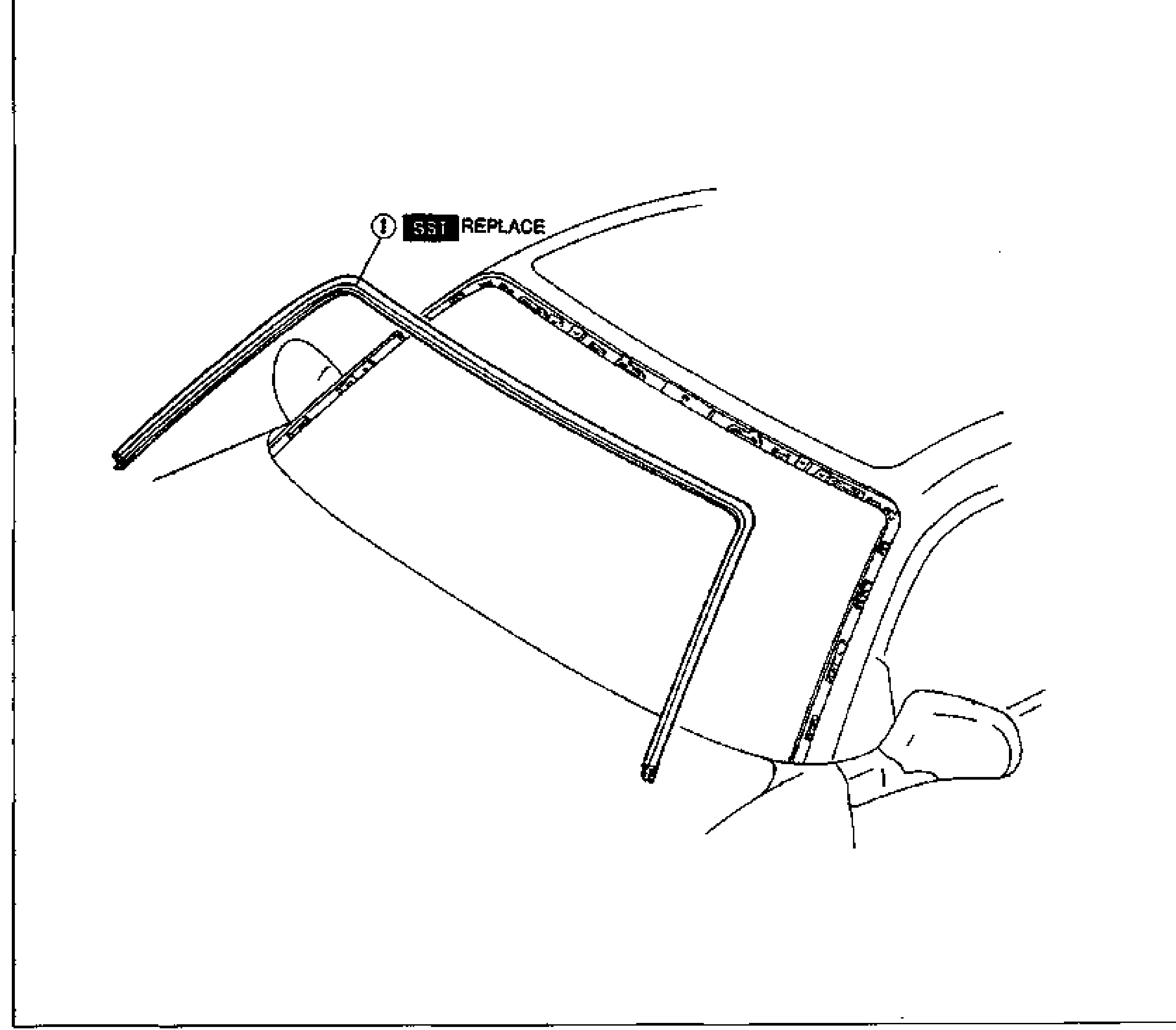
Molding
S-22Diagram of the windshield molding at the upper-left A-pillar/roof corner of the vehicle. Callout 1 with an 'SST' and 'REPLACE' marker points to the windshield molding strip running along the windshield perimeter; the side mirror and front fender are shown for orientation.
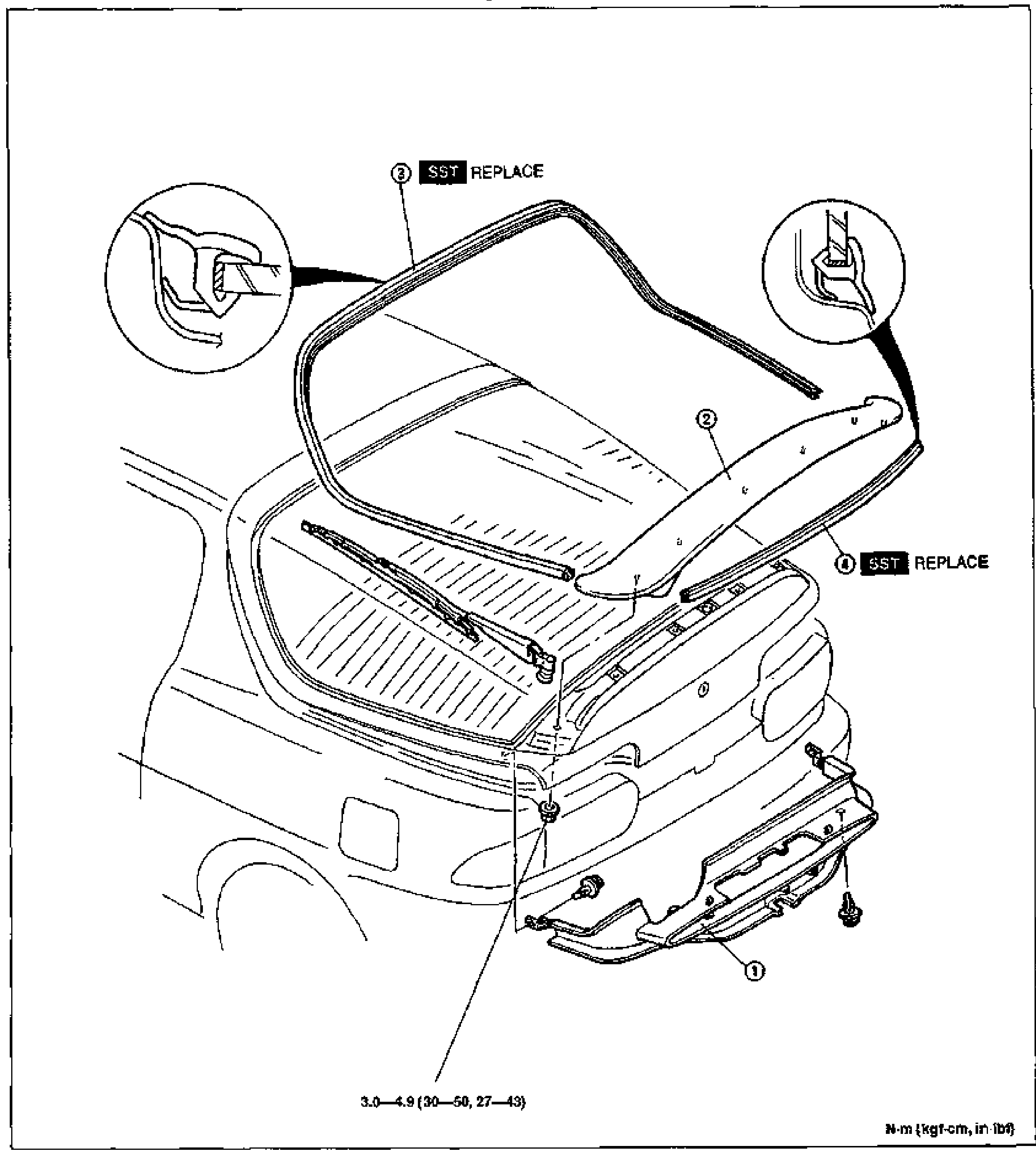
Molding — Liftgate Molding / Vertical Window Molding
S-25Exploded view of the liftgate and rear window area showing the liftgate molding and vertical window molding installation. Numbered balloons: 1 liftgate lower trim (lower right), 2 rear spoiler / liftgate area, 3 liftgate molding (marked SST REPLACE, top), 4 vertical window molding (marked SST REPLACE, right). Two inset detail circles at upper corners show molding cross-sections. A tightening-torque callout '3.0-4.9 (30-50, 27-43) N·m (kgf·cm, in·lbf)' is shown at bottom.
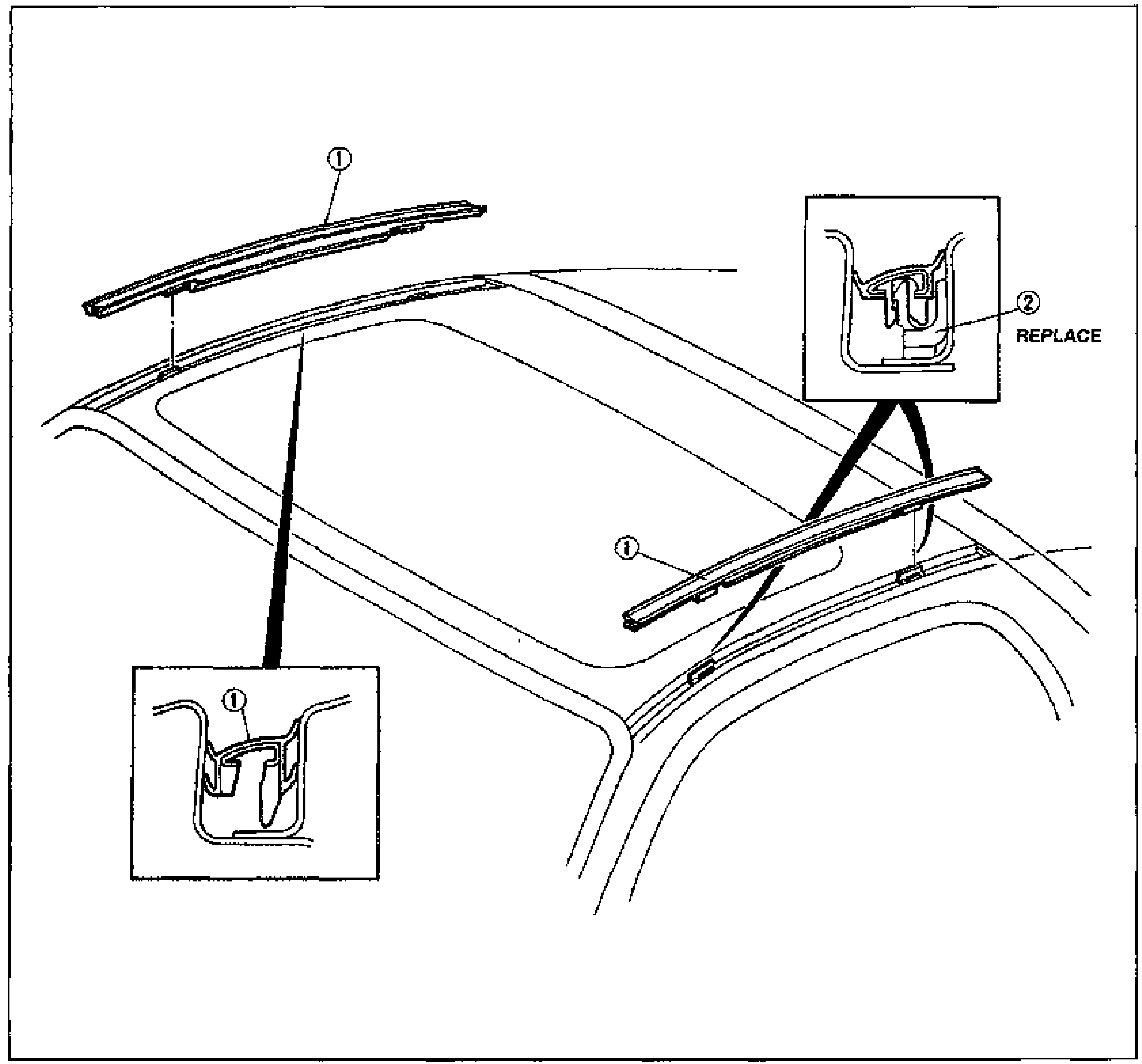
ROOF MOLDING
S-30Exploded view of the roof showing roof molding removal/installation. Callout 1 (Roof molding) points to two roof side moldings; two inset detail views show the molding cross-section and clip engagement. The upper-right inset (callout 2, Clip) is marked REPLACE. The lower-left inset shows the molding-to-clip cross section (callout 1).
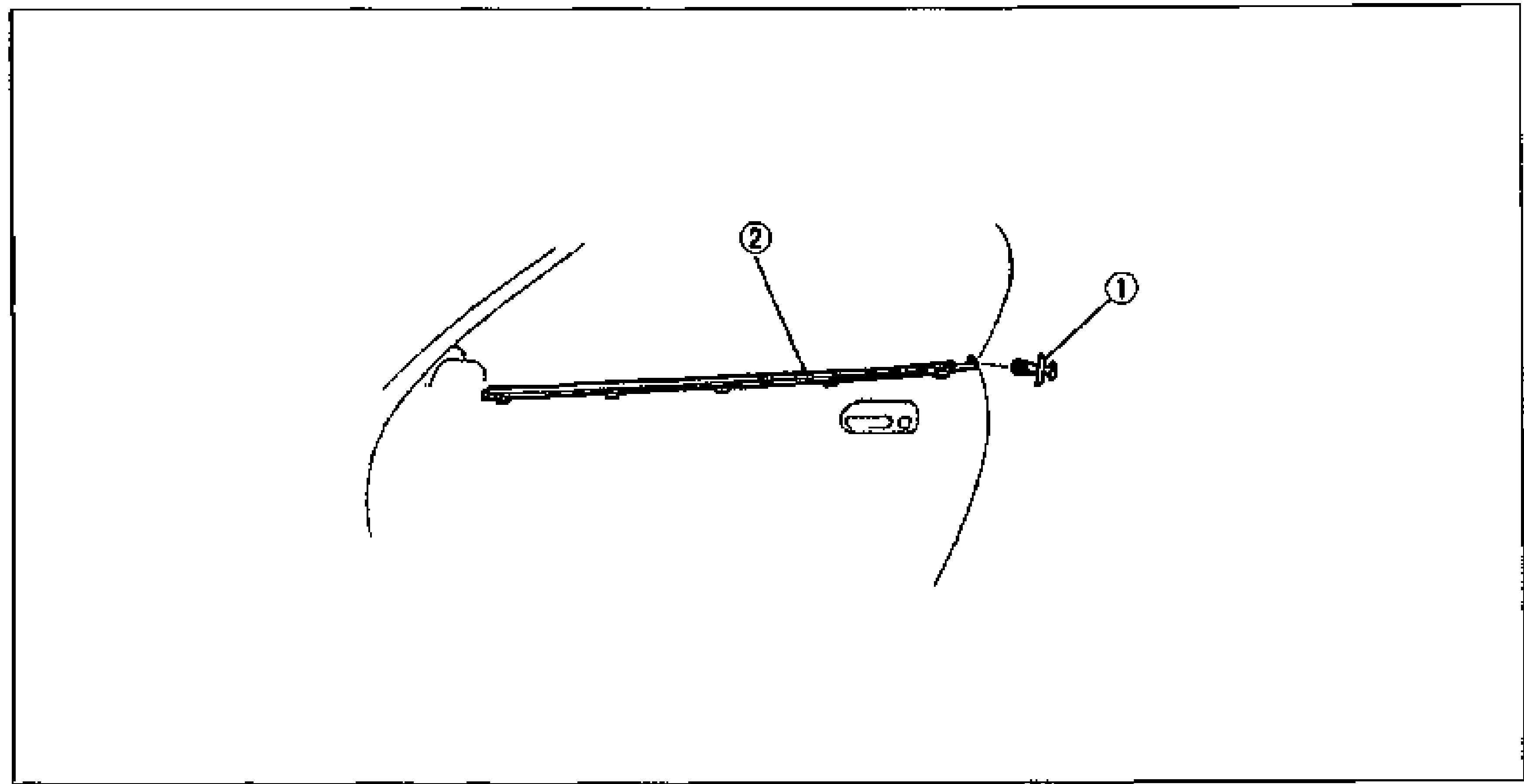
MOLDING
S-31Exploded view of beltline molding on the door. Callout 1 (Fastener) points to a clip/grommet on the right; callout 2 (Beltline molding) points to the long molding strip along the door belt line.
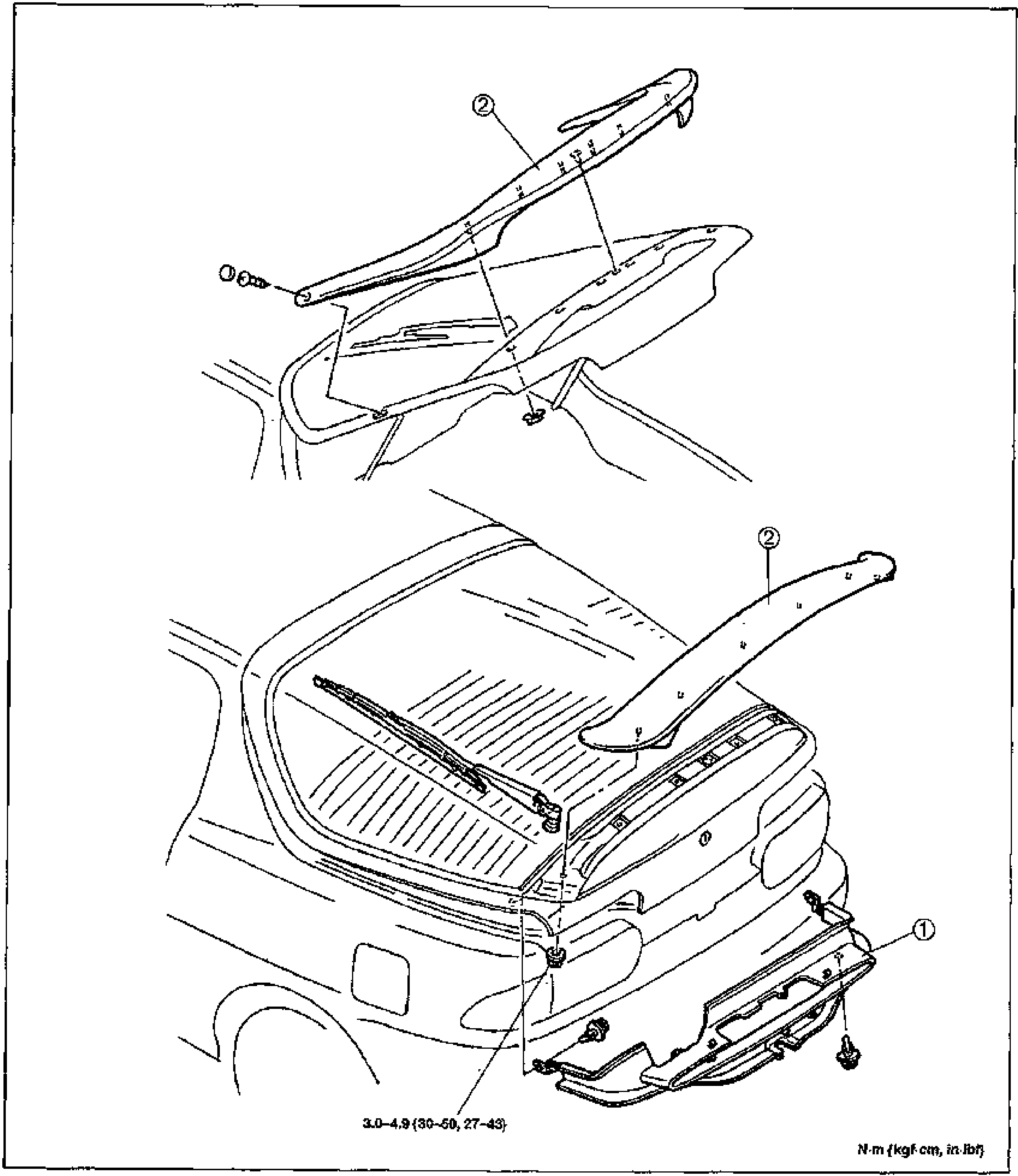
REAR SPOILER
S-32Exploded view of the rear spoiler and liftgate. Callout 2 (Rear spoiler) points to the spoiler shown lifted off the liftgate and again mounted on the rear of the body. Callout 1 (Liftgate lower trim) points to the lower trim panel at the rear bumper area. Torque value 3.0—4.9 N·m (30—50 kgf·cm, 27—43 in-lbf) shown at the bottom for the mounting fasteners.
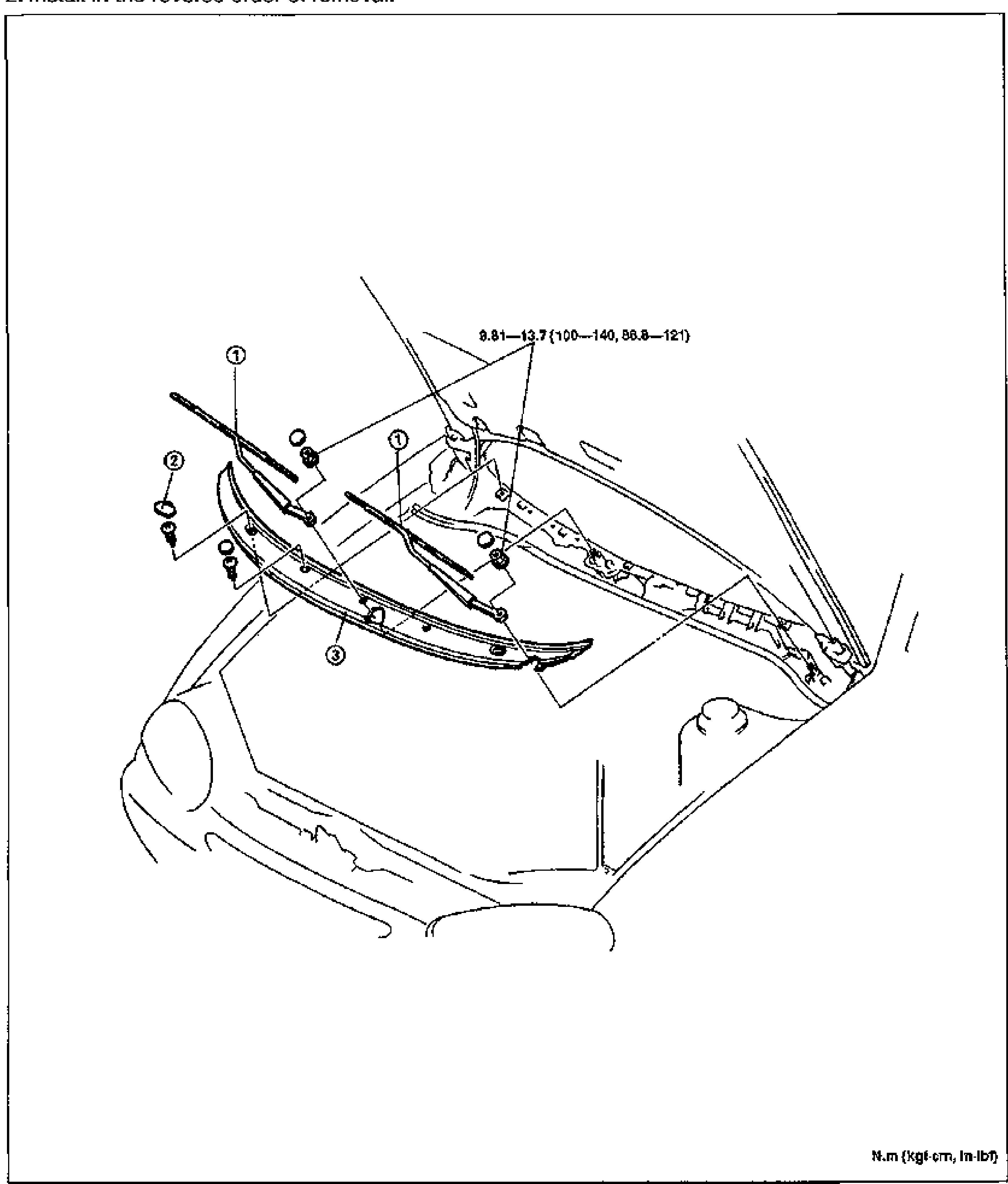
COWL GRILLE
S-33Exploded view of the cowl grille area at the base of the windshield with the front of the car visible. Callout 1 (Windshield wiper arm and blade), callout 2 (Cowl cap), and callout 3 (Cowl grille) are shown with their mounting hardware. Torque value 9.81—13.7 N·m (100—140 kgf·cm, 86.8—121 in-lbf) shown for the wiper-arm pivot nuts.
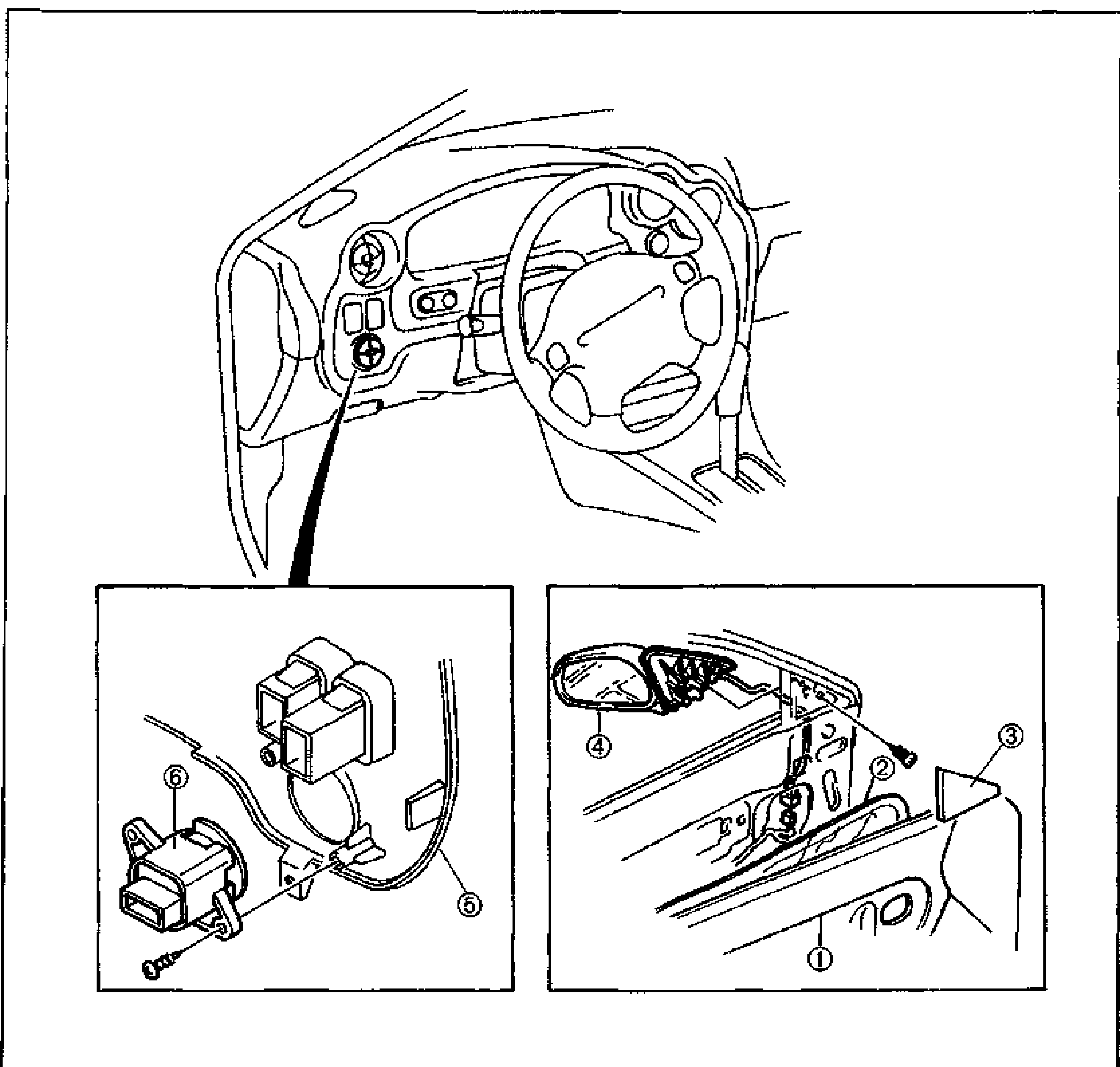
POWER OUTSIDE MIRROR
S-34Composite exploded view of the power outside mirror and switch. Top: interior view of the dash with steering wheel showing the mirror switch location. Bottom-left inset: power outside mirror switch (callout 6) and meter hood (callout 5) connector detail. Bottom-right inset: the door showing door trim (callout 1), inner garnish (callout 3), the power outside mirror (callout 4) and its mounting (callout 2).
POWER OUTSIDE MIRROR
S-34Composite exploded view of the power outside mirror and switch. Top: interior view of the dash with steering wheel showing the mirror switch location. Bottom-left inset: power outside mirror switch (callout 6) and meter hood (callout 5) connector detail. Bottom-right inset: the door showing door trim (callout 1), inner garnish (callout 3), the power outside mirror (callout 4) and its mounting (callout 2).
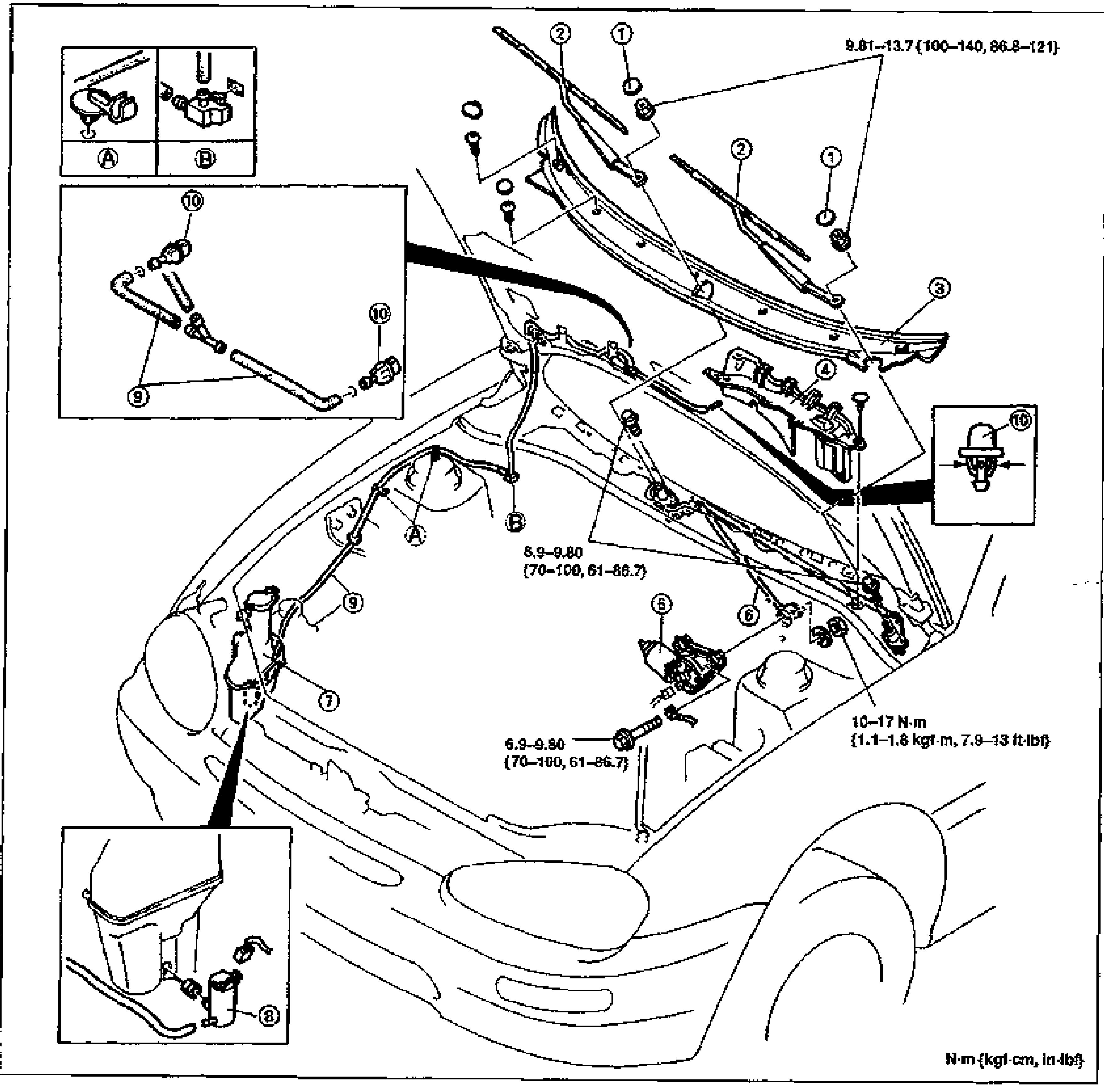
WINDSHIELD WIPER AND WASHER
S-36Large exploded view of the windshield wiper and washer system over the front of the car. Shows wiper arms and blades (1, 2), cowl grille (3), baffle (4), wiper motor (5), wiper link (6), washer tank (7), washer motor (8), washer pipe (9), and washer nozzle (10). Inset details A and B show clip/grommet attachments; another inset (top-left) shows the washer pipe/nozzle routing (9, 10). Torque values shown: 9.81—13.7 N·m (100—140 kgf·cm, 86.8—121 in-lbf) for the wiper arm pivot nuts; 8.9—9.80 N·m (70—100 kgf·cm, 61—86.7 in-lbf) and 6.9—9.80 N·m (70—100 kgf·cm, 61—86.7 in-lbf) for link/motor bolts; 10—17 N·m (1.1—1.8 kgf·m, 7.9—13 ft-lbf) for the wiper motor mounting.
WINDSHIELD WIPER AND WASHER
S-36Large exploded view of the windshield wiper and washer system over the front of the car. Shows wiper arms and blades (1, 2), cowl grille (3), baffle (4), wiper motor (5), wiper link (6), washer tank (7), washer motor (8), washer pipe (9), and washer nozzle (10). Inset details A and B show clip/grommet attachments; another inset (top-left) shows the washer pipe/nozzle routing (9, 10). Torque values shown: 9.81—13.7 N·m (100—140 kgf·cm, 86.8—121 in-lbf) for the wiper arm pivot nuts; 8.9—9.80 N·m (70—100 kgf·cm, 61—86.7 in-lbf) and 6.9—9.80 N·m (70—100 kgf·cm, 61—86.7 in-lbf) for link/motor bolts; 10—17 N·m (1.1—1.8 kgf·m, 7.9—13 ft-lbf) for the wiper motor mounting.
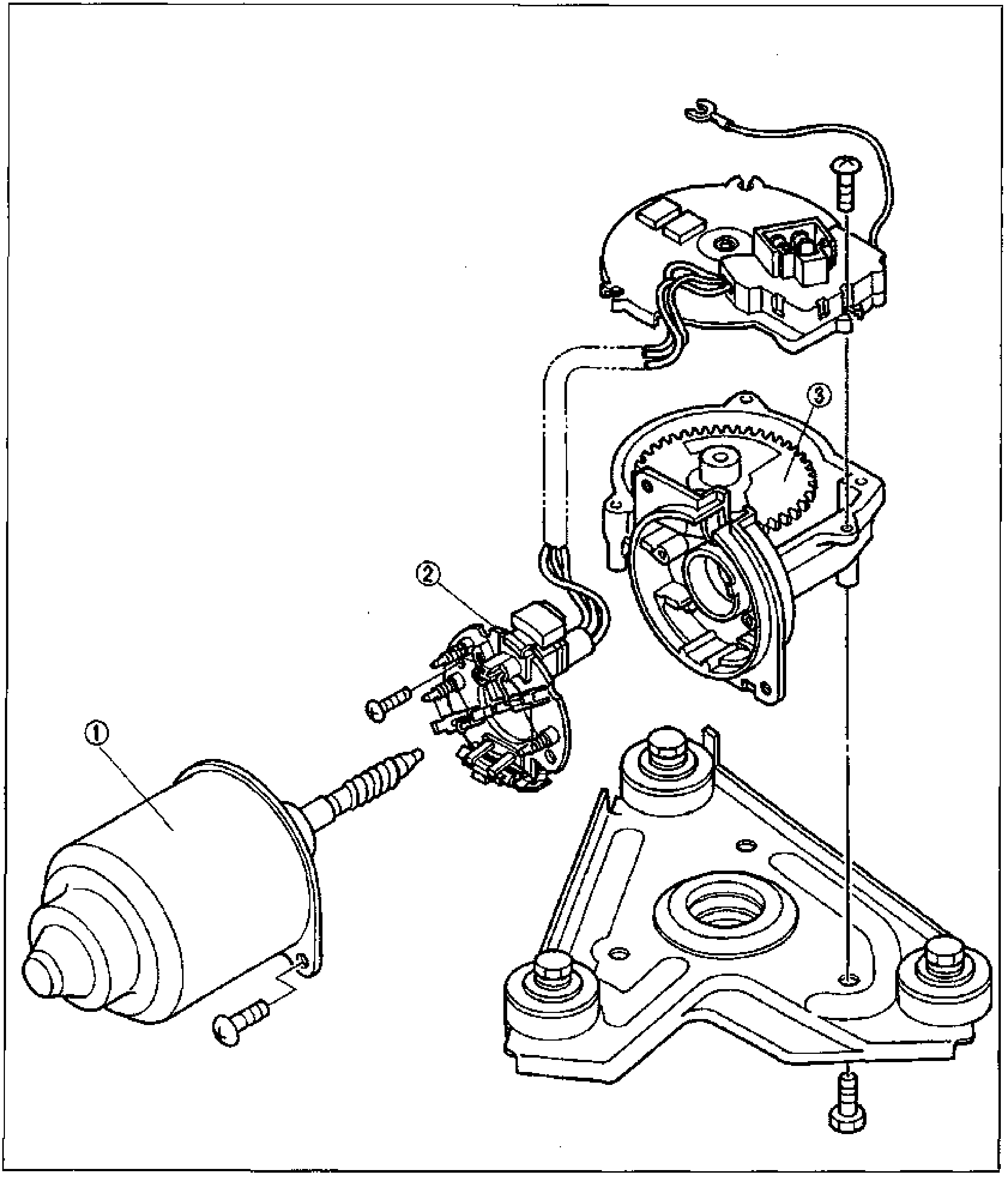
WINDSHIELD WIPER AND WASHER
S-38Exploded view of the windshield wiper motor disassembly. Callout 1 (Wiper motor) is the motor body/armature at lower left; callout 2 (Brush plate holder) is the brush plate assembly in the center; callout 3 (Motor gear assembly) is the gear housing and gear at upper right, with the mounting bracket and screws at the bottom.
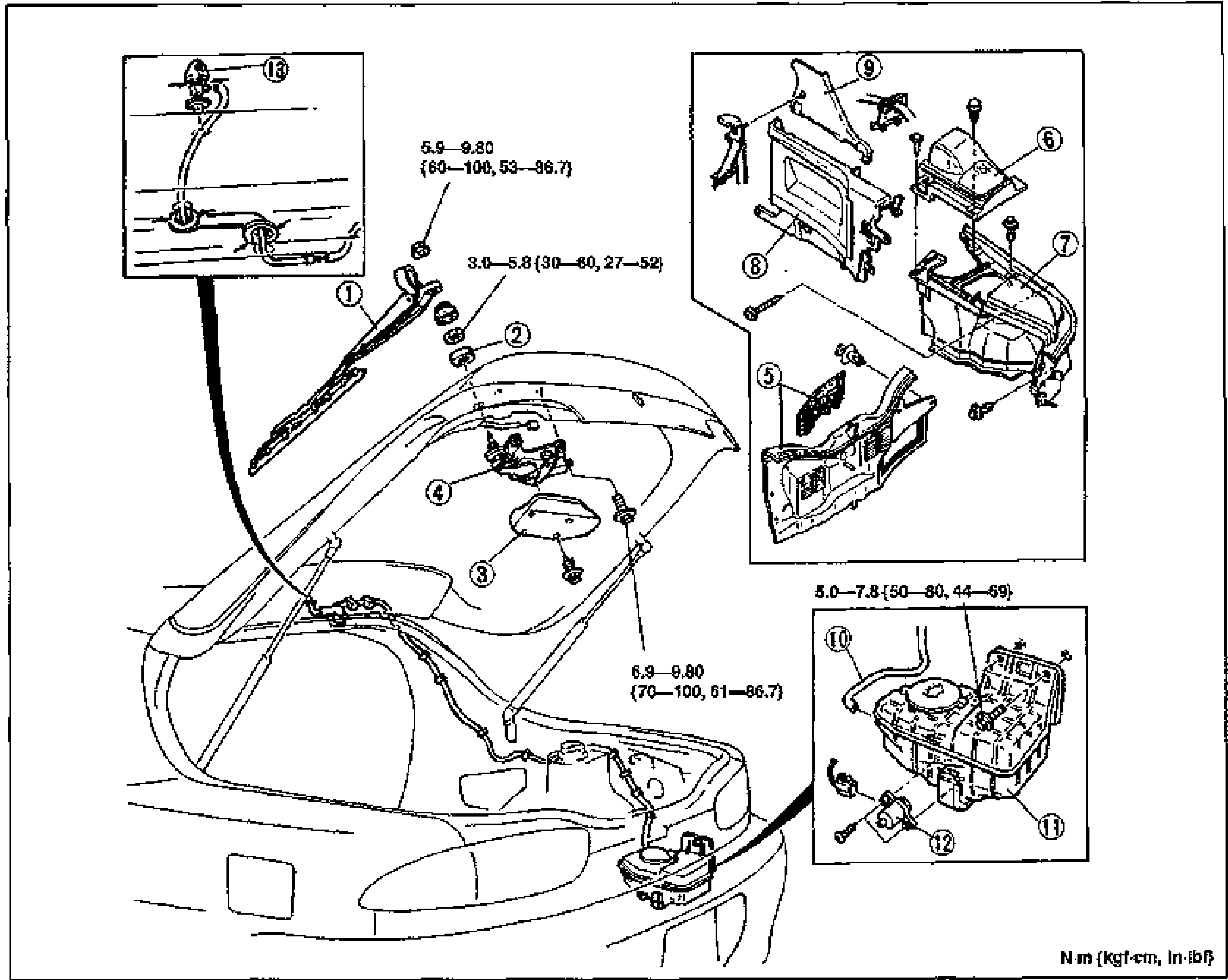
REAR WIPER AND WASHER
S-39Composite exploded view of the rear wiper and washer system on the liftgate/hatch. Main view (left/center) shows the rear of the car with rear wiper arm and blade (1), outer bushing (2), rear wiper cover (3) and rear wiper motor (4). Top-right inset shows trunk/rear interior trim panels: trunk end trim (5), rear speaker cover (6), trunk side trim (7), quarter trim (8), B-pillar trim (9). Bottom-right inset shows the rear washer pipe (10), rear washer tank (11) and rear washer motor (12). A top-left inset shows the rear washer nozzle (13). Torque values: 5.9—9.80 N·m (60—100 kgf·cm, 53—86.7 in-lbf); 3.0—5.8 N·m (30—60 kgf·cm, 27—52 in-lbf); 6.9—9.80 N·m (70—100 kgf·cm, 61—86.7 in-lbf); 5.0—7.8 N·m (50—80 kgf·cm, 44—69 in-lbf).
REAR WIPER AND WASHER
S-39Composite exploded view of the rear wiper and washer system on the liftgate/hatch. Main view (left/center) shows the rear of the car with rear wiper arm and blade (1), outer bushing (2), rear wiper cover (3) and rear wiper motor (4). Top-right inset shows trunk/rear interior trim panels: trunk end trim (5), rear speaker cover (6), trunk side trim (7), quarter trim (8), B-pillar trim (9). Bottom-right inset shows the rear washer pipe (10), rear washer tank (11) and rear washer motor (12). A top-left inset shows the rear washer nozzle (13). Torque values: 5.9—9.80 N·m (60—100 kgf·cm, 53—86.7 in-lbf); 3.0—5.8 N·m (30—60 kgf·cm, 27—52 in-lbf); 6.9—9.80 N·m (70—100 kgf·cm, 61—86.7 in-lbf); 5.0—7.8 N·m (50—80 kgf·cm, 44—69 in-lbf).
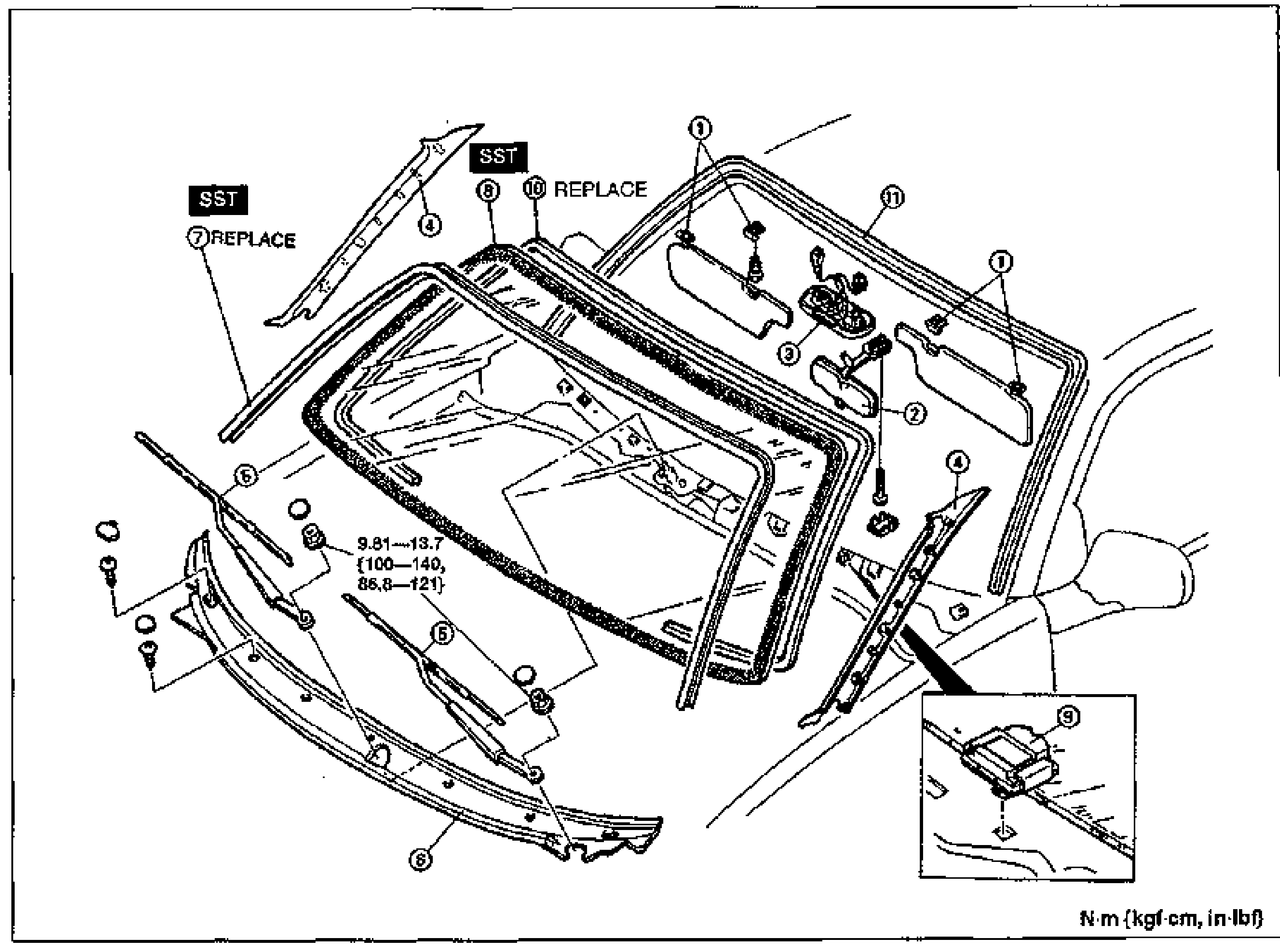
WINDSHIELD
S-41Exploded view of the windshield assembly and surrounding trim. Numbered balloon callouts identify sunvisor and adapter (1), rearview mirror (2), overhead console (3), A-pillar trim (4), windshield wiper arm and blade (5), cowl grille (6), windshield molding (7, marked SST/REPLACE), windshield glass (8, marked SST), spacer (9, in lower-right inset), dam (10, REPLACE), and protector (11). A tightening torque callout reads 9.81—13.7 N·m {100—140, 86.8—121}; unit note 'N·m (kgf·cm, in·lbf)' at bottom right.
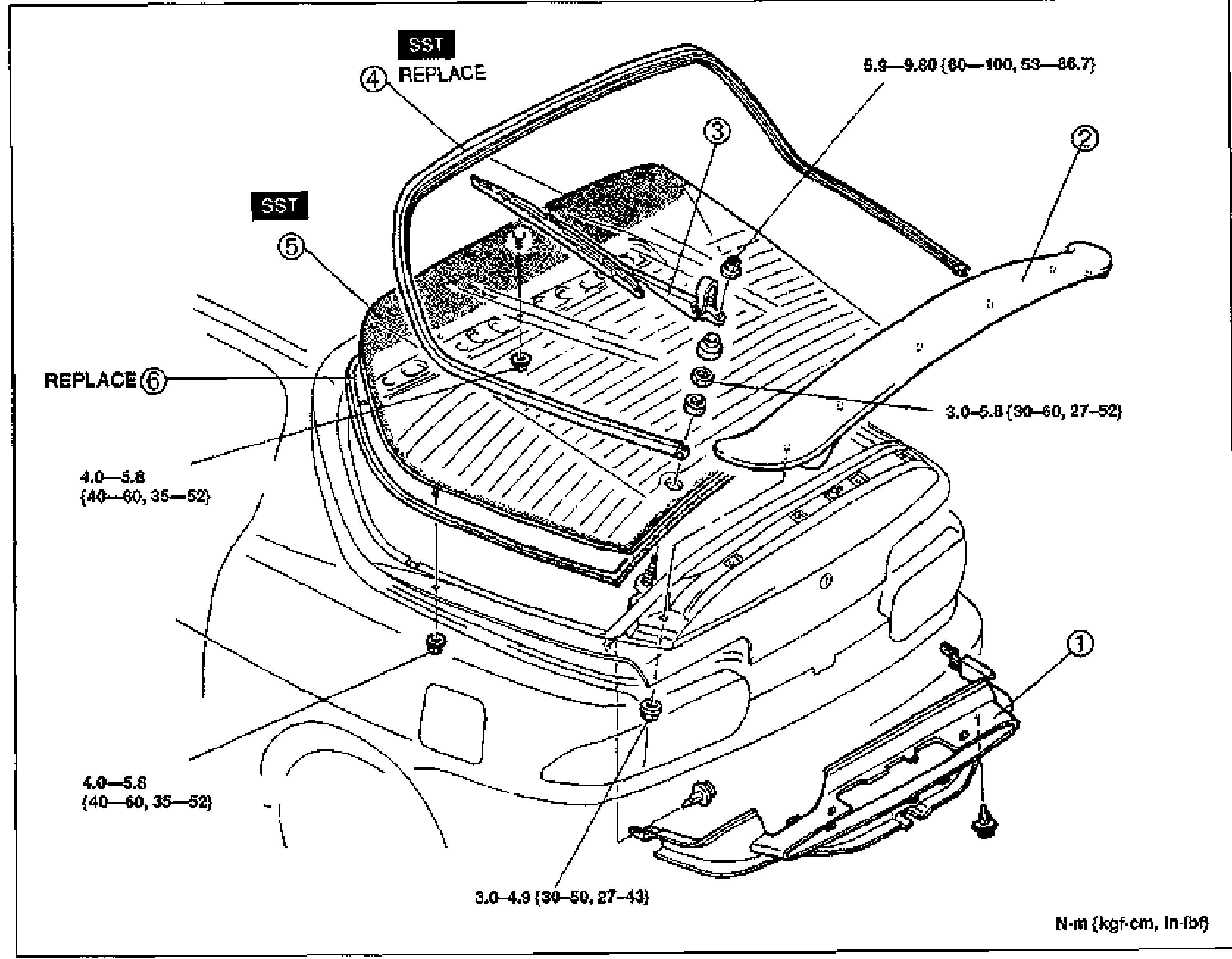
LIFTGATE GLASS
S-45Exploded view of the rear liftgate glass assembly and surrounding trim. Numbered balloon callouts identify liftgate lower trim (1), rear spoiler (2), rear wiper arm and blade (3, marked SST/REPLACE), liftgate molding (4), liftgate glass (5, marked SST), and dam (6, REPLACE). Tightening torque callouts: 5.9—9.80 {60—100, 53—86.7}, 3.0—5.8 {30—60, 27—52}, 4.0—5.8 {40—60, 35—52}, 3.0—4.9 {30—50, 27—43}. Unit note 'N·m (kgf·cm, in·lbf)'.
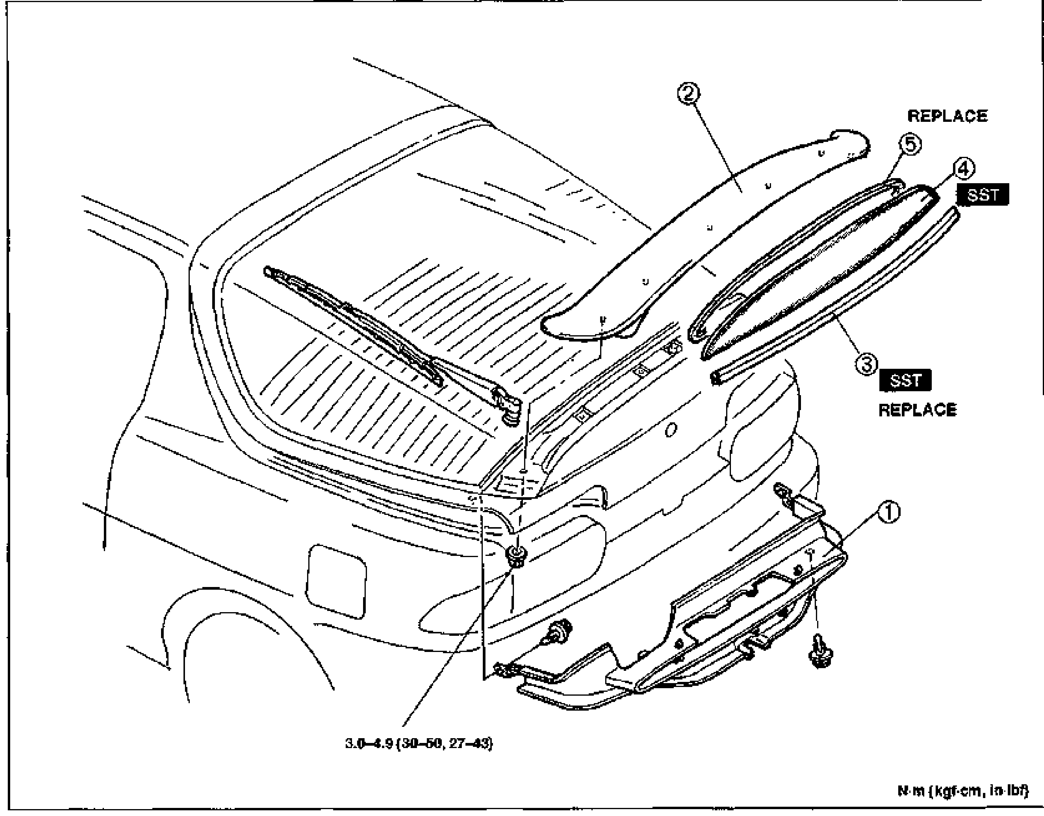
VERTICAL WINDOW GLASS
S-49Exploded view of the rear vertical window glass assembly and surrounding trim. Numbered balloon callouts identify liftgate lower trim (1), rear spoiler (2), vertical window molding (3, marked SST/REPLACE), vertical window glass (4, marked SST), and dam (5, REPLACE). Tightening torque callout 3.0—4.9 {30—50, 27—43}. Unit note 'N·m (kgf·cm, in·lbf)'.
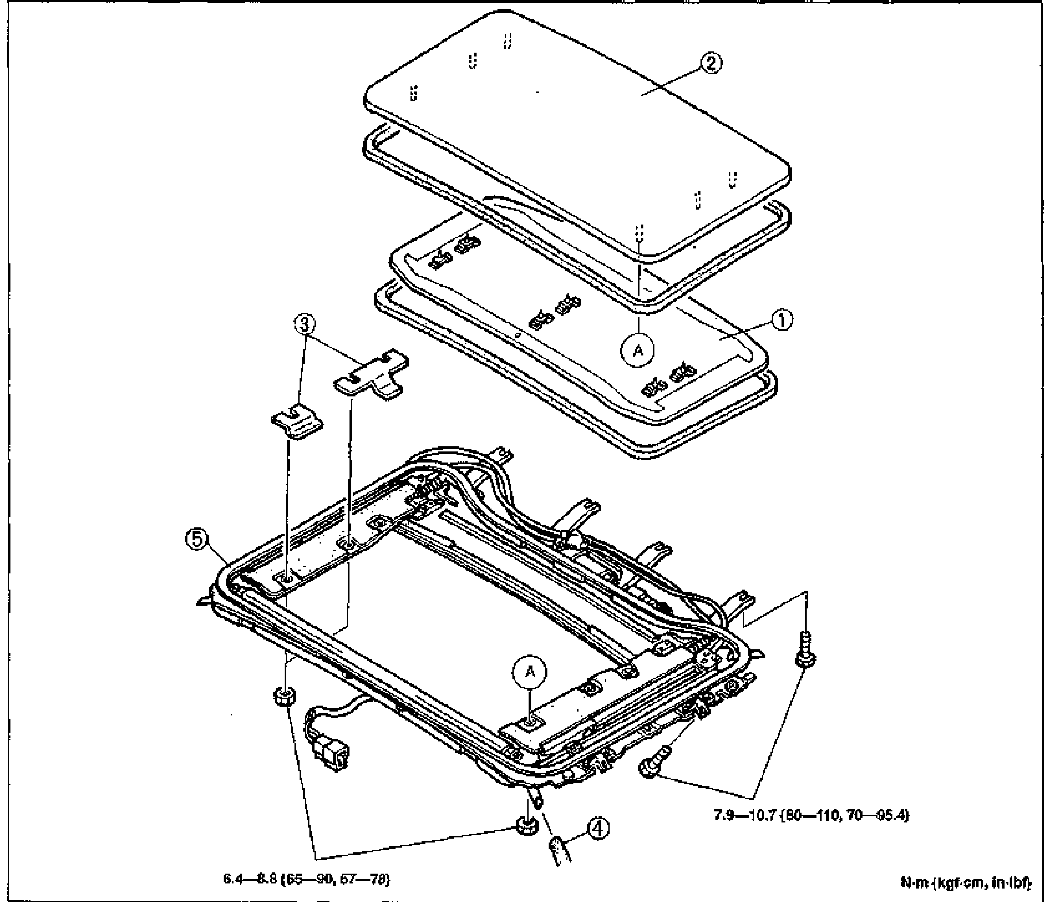
SLIDING SUNROOF
S-53Exploded view of the sliding sunroof assembly. From top: slide panel (2), sunroof trim (1), sunroof shim (3), drain hose (4), and the sunroof drive unit / frame (5) with attaching screws. Letter 'A' callouts mark alignment/attachment points. Torque specs printed at bottom: 6.4—8.8 N·m {65—90 kgf·cm, 57—78 in·lbf} and 7.9—10.7 N·m {80—110 kgf·cm, 70—95.4 in·lbf}. Units note: N·m {kgf·cm, in·lbf}.
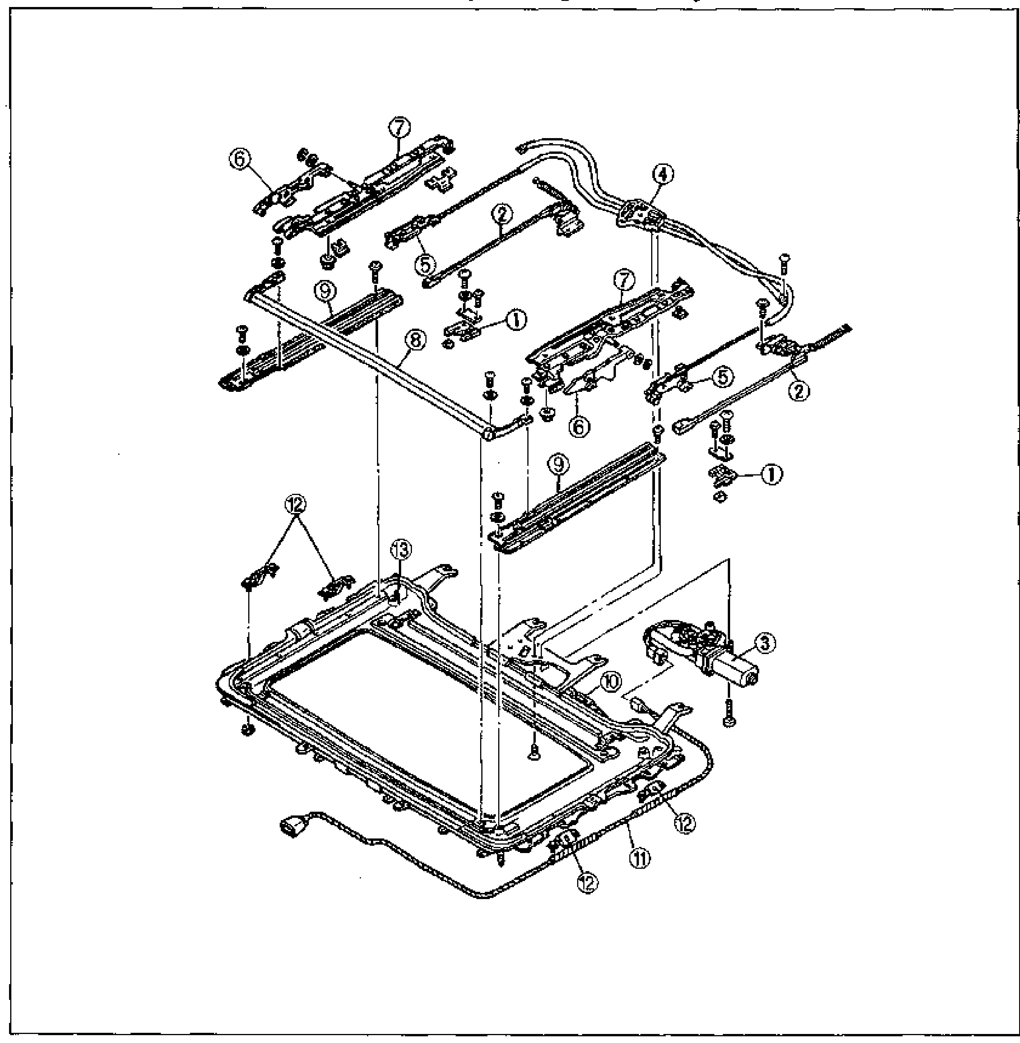
SLIDING SUNROOF
S-57Exploded view of the sunroof drive unit disassembly. Numbered balloon callouts 1-13 identify: cable holder, shutting, sunroof motor assembly, drive unit, rear guide, front guide, lower panel, wind deflector, guide rail, sunroof relay, harness assembly, set bracket, and sunroof frame. Components fan out from the sunroof frame at bottom with attaching screws.
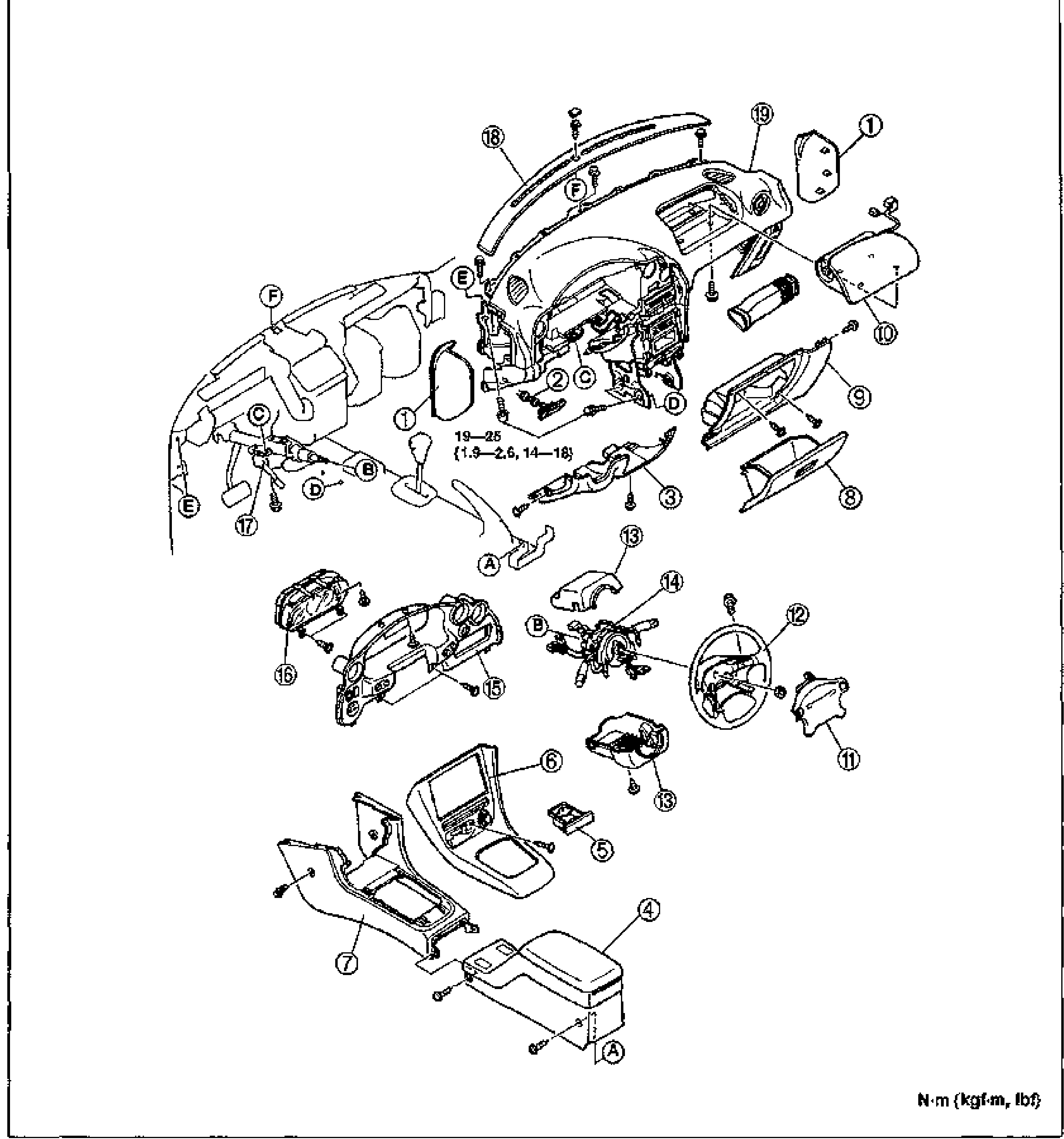
DASHBOARD AND CONSOLE — Component Removal / Installation
S-61Large exploded view of the dashboard and console assembly with numbered balloon callouts 1-19 and lettered removal-note callouts A-F. Shows the dash panel, instrument cluster, steering wheel, air bag module, glove box, console box and lid. A torque value 19—25 {1.9—2.6, 14—18} is noted near the center. Units labelled N·m {kgf·m, lbf}.
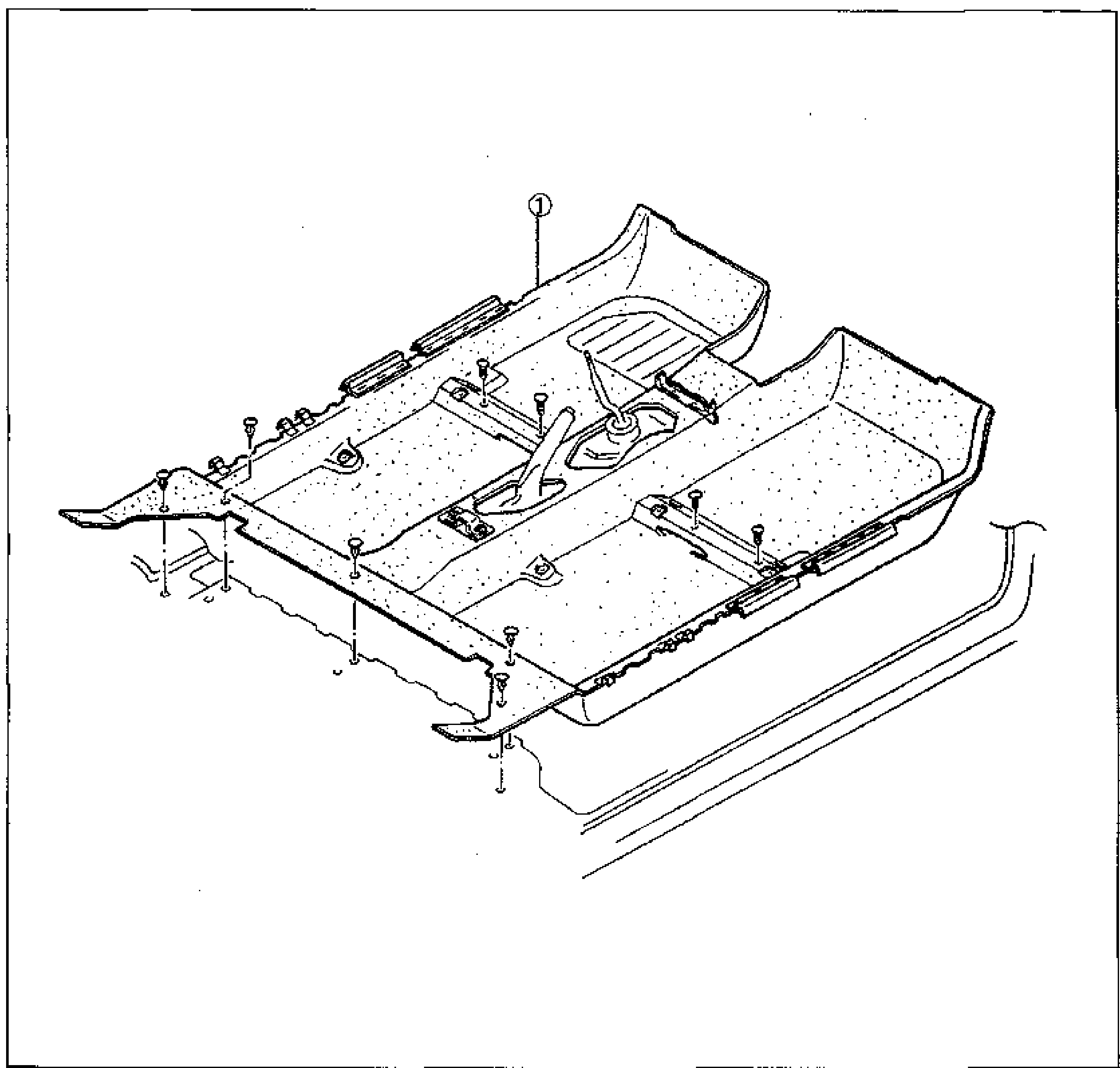
FLOOR COVERING — Components Removal / Installation
S-69Large exploded view of the cabin floor covering, showing the cabin carpet (callout 1) lifted off the floor pan with the shift lever opening, seat mounting holes and retaining screws/clips visible. The body sill is shown at lower right.
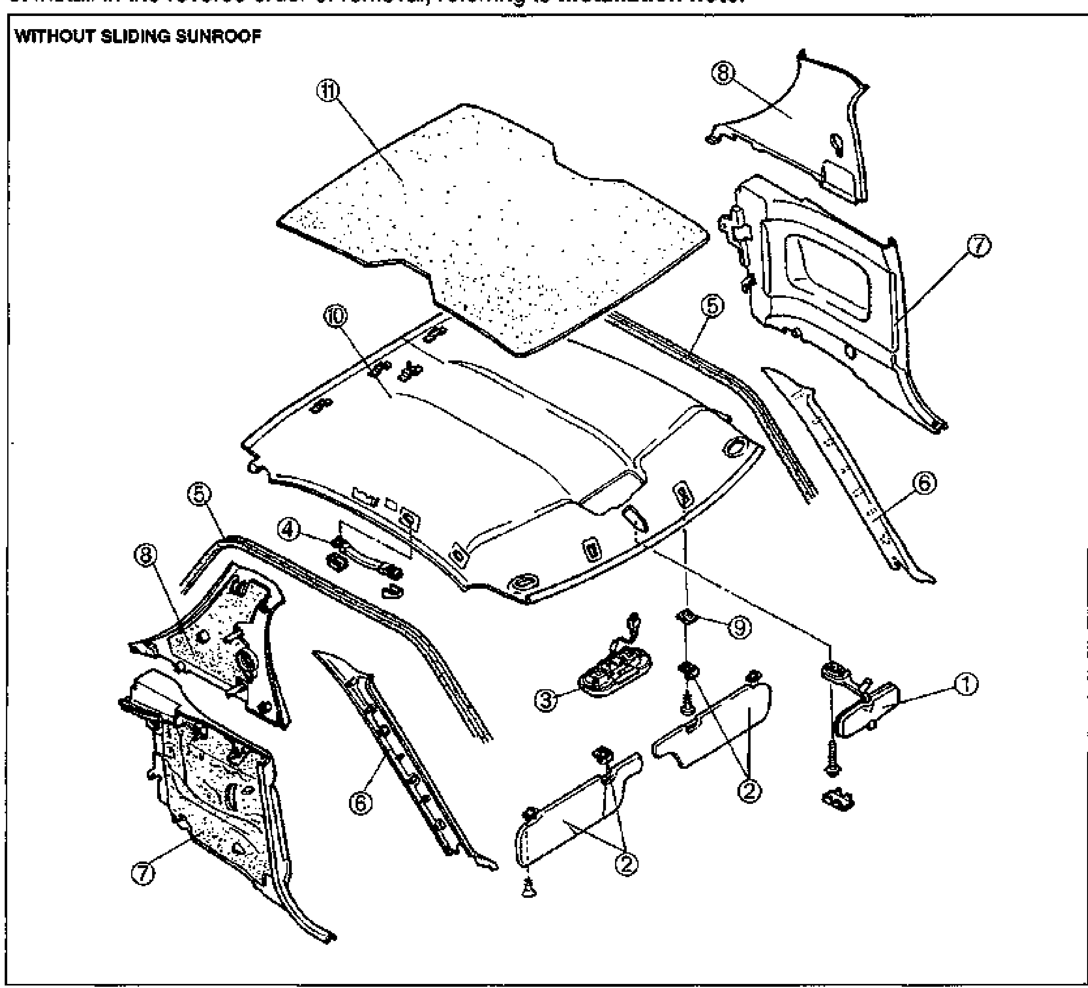
HEADLINER
S-70Exploded view of the headliner assembly and surrounding interior trim, labeled WITHOUT SLIDING SUNROOF. Numbered balloon callouts identify the rearview mirror, sunvisors, overhead console, assist handle, seaming welt, A-pillar trim, quarter trim, B-pillar trim, fastener, headliner, and insulator. Components float in their installed positions around the roof.
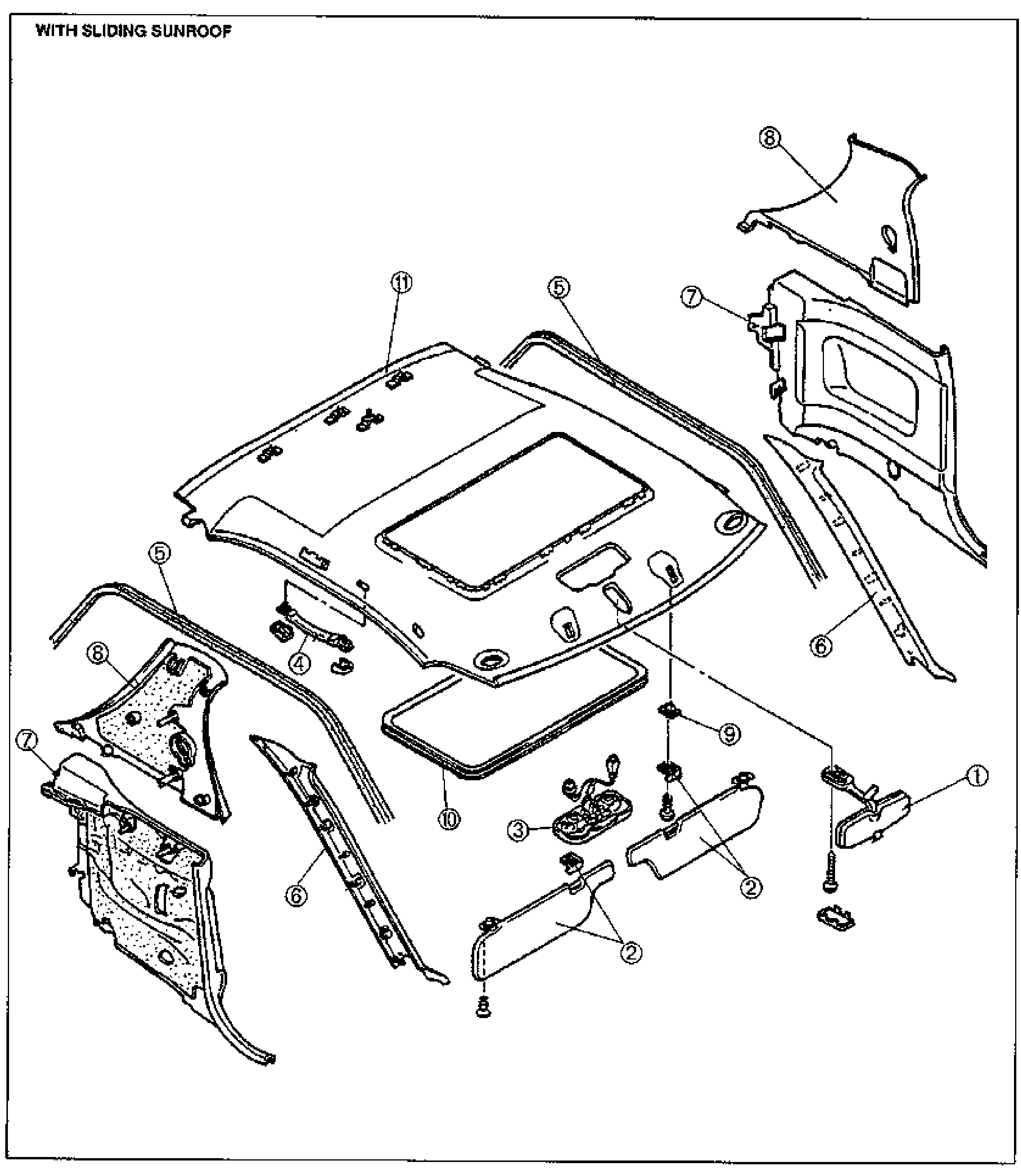
HEADLINER
S-71Exploded view of the headliner assembly and surrounding interior trim for the vehicle WITH SLIDING SUNROOF. The headliner has a sunroof opening cut out. Numbered balloon callouts identify the rearview mirror, sunvisors, overhead console, assist handle, seaming welt, A-pillar trim, quarter trim, B-pillar trim, fastener, sunroof seaming welt, and headliner.
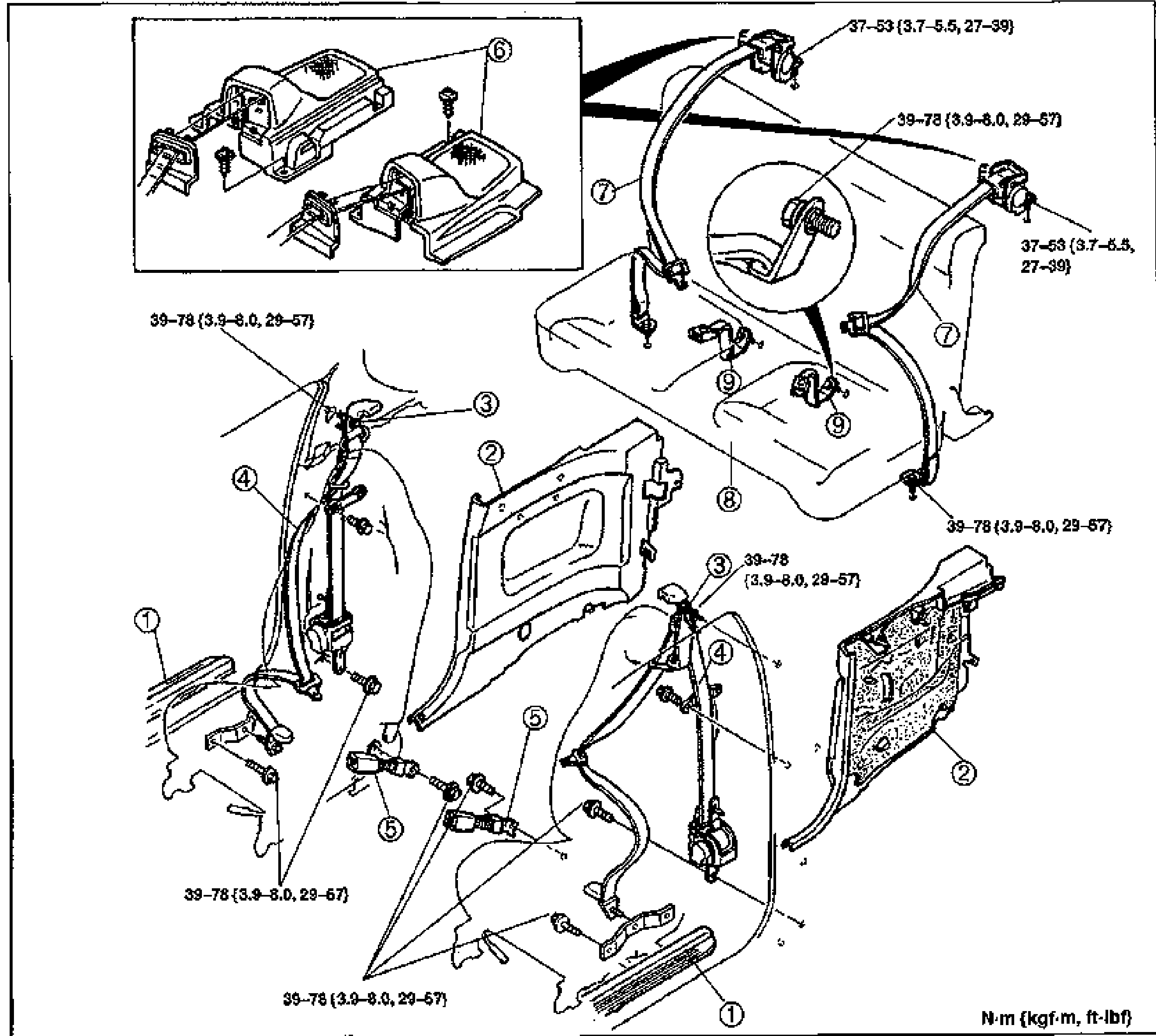
SEAT BELT
S-73Exploded view of front and rear seat belt assemblies with torque values in N·m (kgf·m, ft-lbf). Numbered balloon callouts identify the scuff plate, quarter trim, upper anchor, front seat belt retractor, front buckle, rear speaker cover, rear seat belt, rear seat cushion and rear buckle. An inset top-left magnifies the rear speaker cover (6). Torque tags: 37-53 N·m for anchor bolts and 39-78 N·m for retractor/buckle bolts.
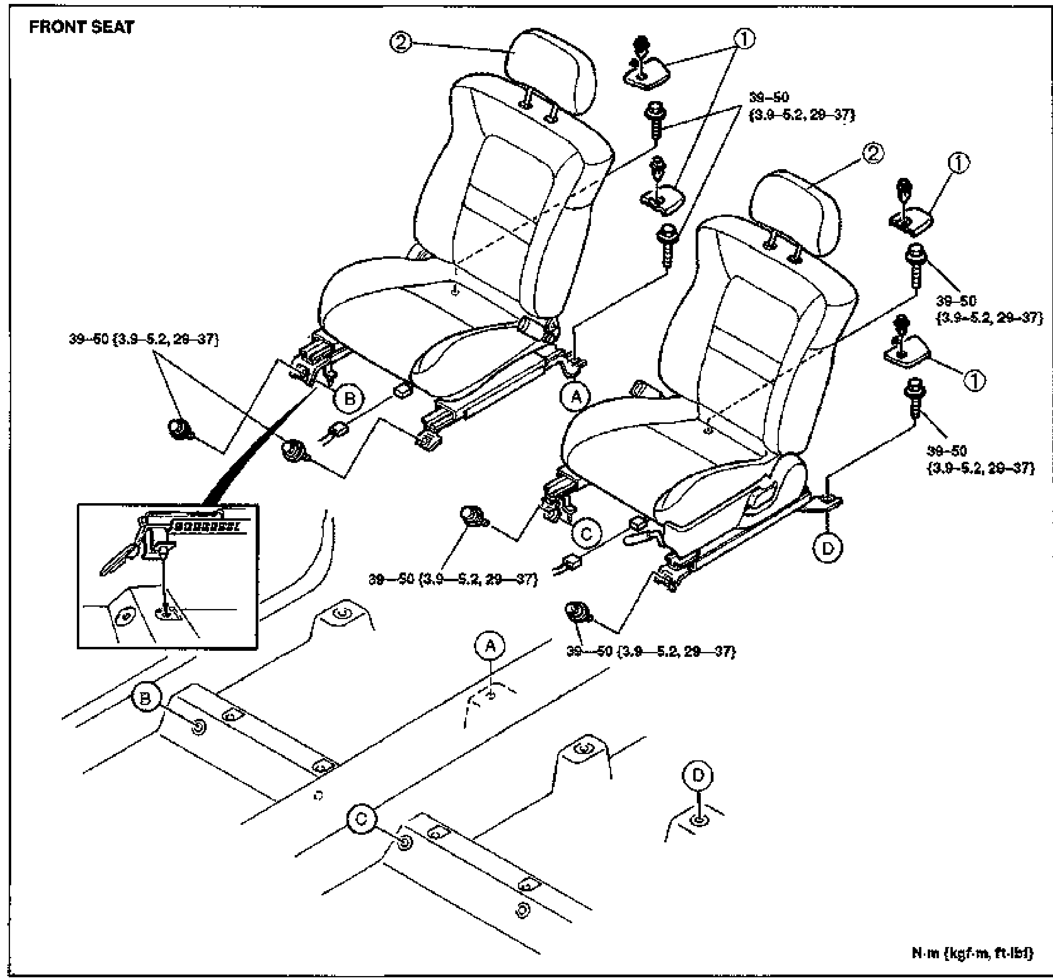
SEAT
S-75FRONT SEAT exploded view of both front seats with mounting bolts and torque values N·m (kgf·m, ft-lbf). Balloon callouts 1 (cover) and 2 (front seat) appear on each seat. Mounting bolt positions are lettered A, B, C, D and shown on the seat rails / floor. An inset bottom-left magnifies the seat track / catch detail. Torque tag 39-50 (3.9-5.2, 29-37) applies to the seat mounting bolts.
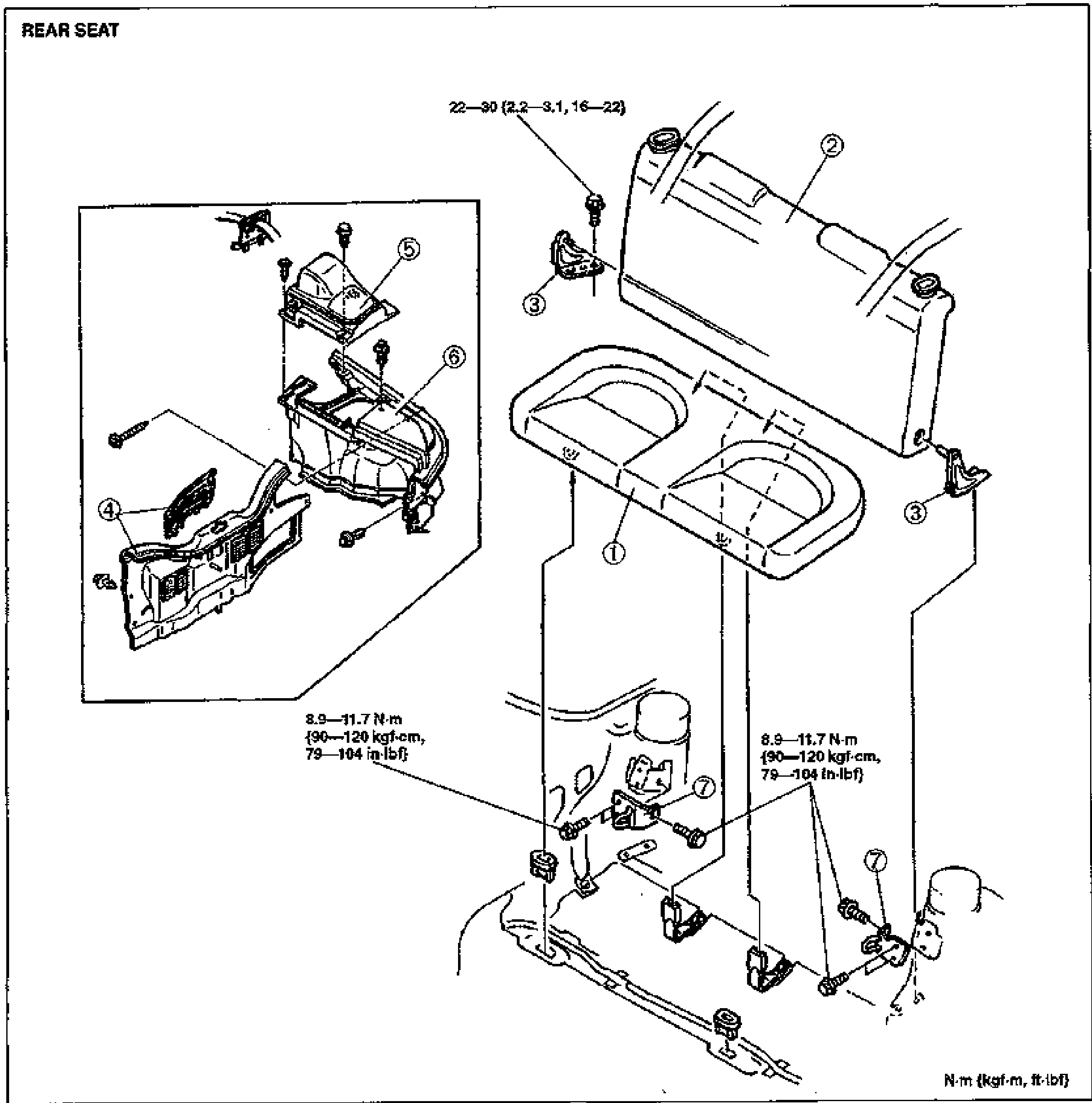
SEAT
S-76REAR SEAT exploded view with torque values N·m (kgf·m, ft-lbf). Right side shows the rear seat cushion (1), rear seat back (2) and rear seat back hinge (3) in installed position. Inset top-left magnifies the rear seat back striker hardware with callouts 4 (trunk end trim), 5 (rear speaker cover), 6 (trunk side trim). Callout 7 marks the rear seat back striker. Torque tags: 22-30 (2.2-3.1, 16-22) for the hinge bolt and 8.9-11.7 N·m (90-120 kgf·cm, 79-104 in·lbf) for the striker bolts.
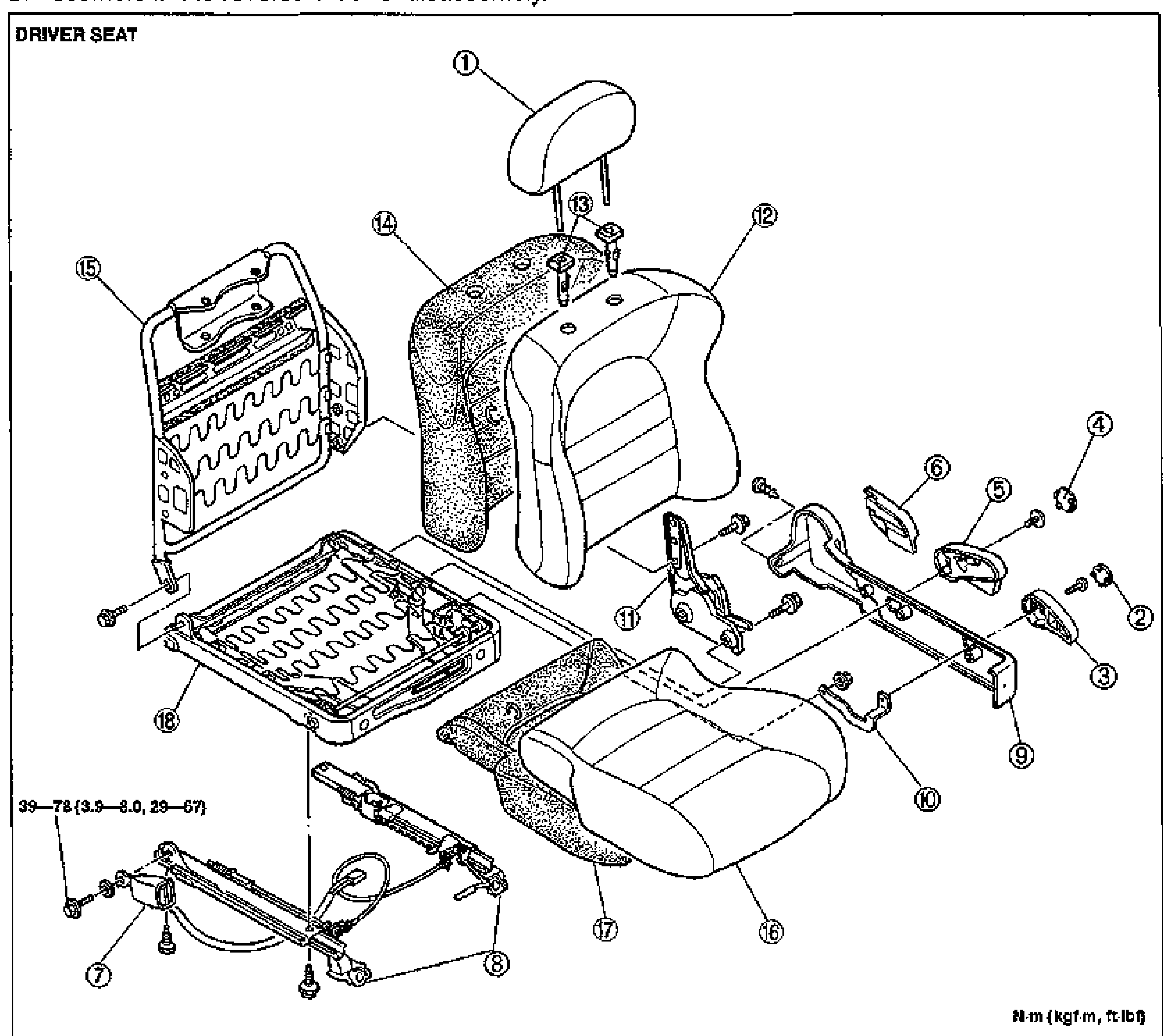
SEAT
S-77DRIVER SEAT disassembly/assembly exploded view with torque value N·m (kgf·m, ft-lbf). Eighteen numbered balloon callouts identify the headrest, tilt/lift/recliner knobs and caps, front buckle, slide adjuster, seat side cover, tilt lever, recliner knuckle, seat back trim/pad/frame, pole guide, seat cushion trim/pad/frame. Torque tag 39-78 (3.9-8.0, 29-57) applies to the slide adjuster bolt.
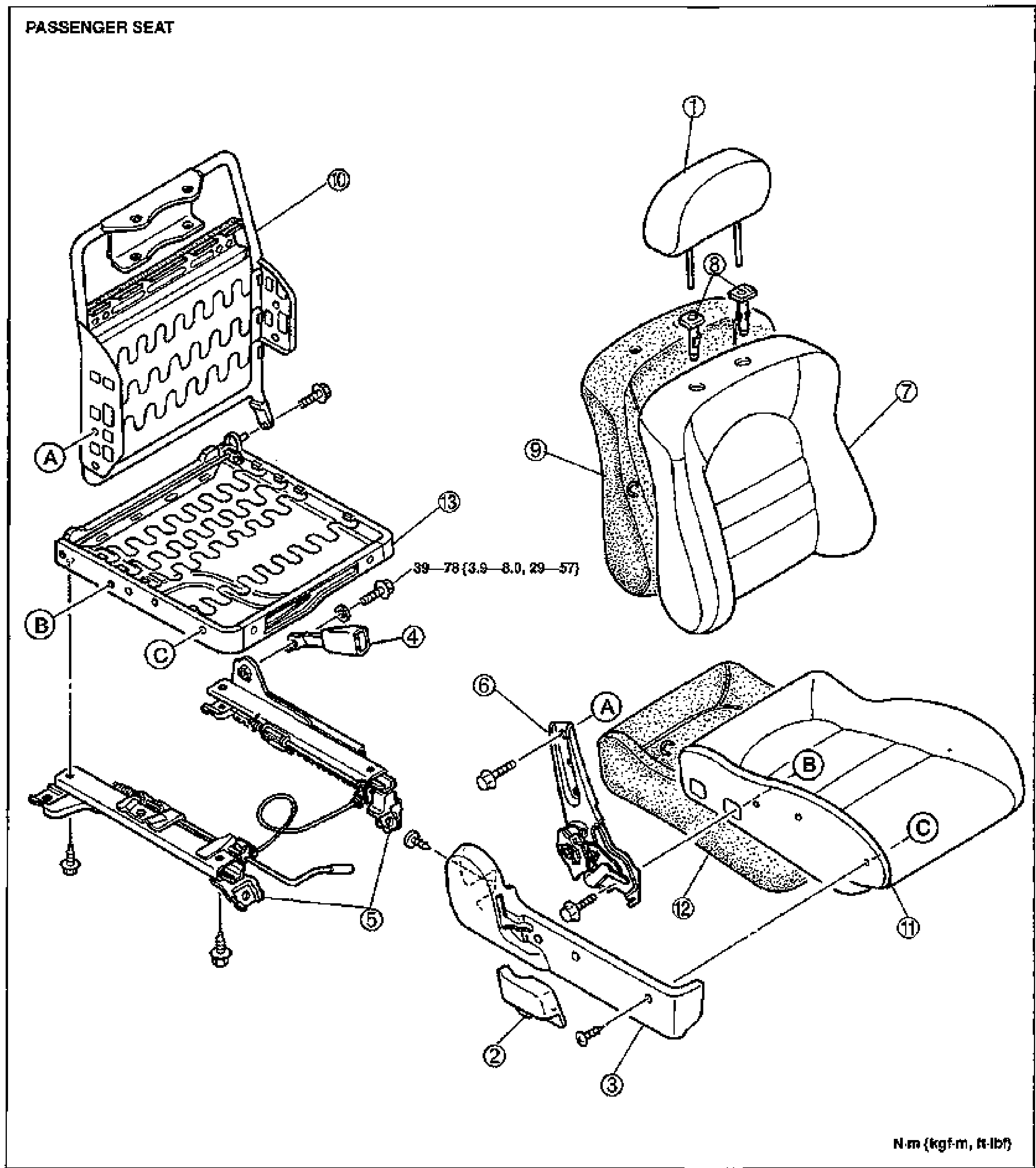
SEAT
S-78PASSENGER SEAT disassembly/assembly exploded view with torque value N·m (kgf·m, ft-lbf). Thirteen numbered balloon callouts identify the headrest, recliner knob, seat side cover, front buckle, slide adjuster, recliner knuckle, seat back trim, pole guide, seat back pad, seat back frame, seat cushion trim, seat cushion pad and seat cushion frame. Lettered points A, B, C mark fastening/locating positions. Torque tag 39-78 (3.9-8.0, 29-57) applies to the slide adjuster bolt.
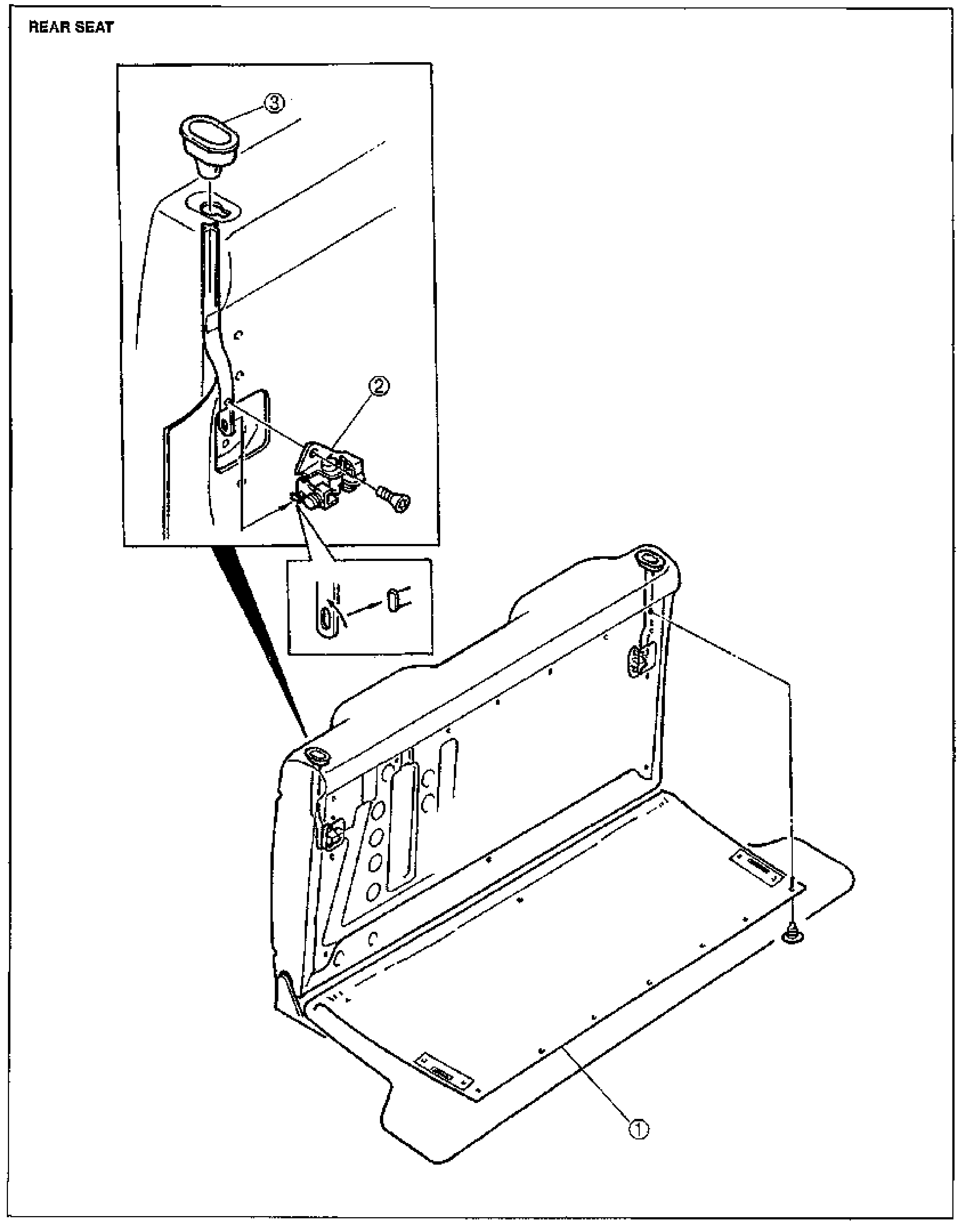
SEAT
S-79REAR SEAT (rear seat back) disassembly/assembly exploded view. The main illustration shows the rear seat back frame folded forward over the trunk carpet (1). An inset top-left magnifies the rear seat back catch lock (2) and its mounting, with the rear seat back catch knob (3) above; a further small detail shows the catch lock pawl. The catch lock is fastened with a TORX-head bolt.