Mazda MX-3 silhouetteMX-3

FRONT SUSPENSION (STRUT) — Front Crossmember parts legend & Removal Note

R-27parts diagram

Engine mounting member service references both section B1 and B2 (covering both B6 and K8 engines). Transverse member and insulator items are annotated (K8 DOHC).

Parts DiagramFig. page R-26 fig1
Parts diagram
#Part NameNotes
1Tie-rod end / Steering knuckleService section N
2Transverse member (K8 DOHC)
3Engine mounting memberService section B1, B2
4Front exhaust pipe
5Stabilizer nuts
6Insulator (K8 DOHC)
7Steering gear and linkageService section N
8Bolts and nuts
9Front lower arm assemblyRemoval / Inspection / Installation page R-18
10Bolts
11Nuts
12Front crossmemberRemoval Note below. Inspect for damage
13Stabilizer bolts
14Stabilizer brackets
15Stabilizer barRemoval Note page R-21, 23
16Stabilizer bushingsInstallation Note page R-21, 23

Removal Note

Front Crossmember

Front Crossmember removal

  1. 1
    Support the crossmember with a jack, and remove the bolts and nuts.
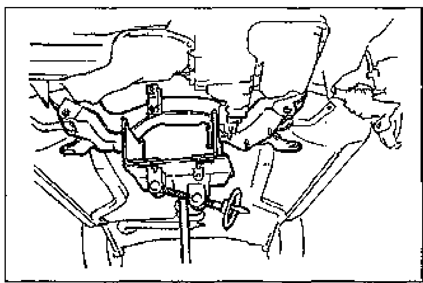
    Underside view of the front crossmember supported by a jack, with the bolts and nuts removed prior to lowering and removing the front crossmember.
  2. 2
    Remove the front crossmember.

Search Manual

Search pages, specs, and procedures