
AIR CONDITIONER — Magnetic Clutch Disassembly / Assembly
G-62parts diagramMAGNETIC CLUTCH
Disassembly / Assembly
- 1Disassemble in the order as shown in the figure.
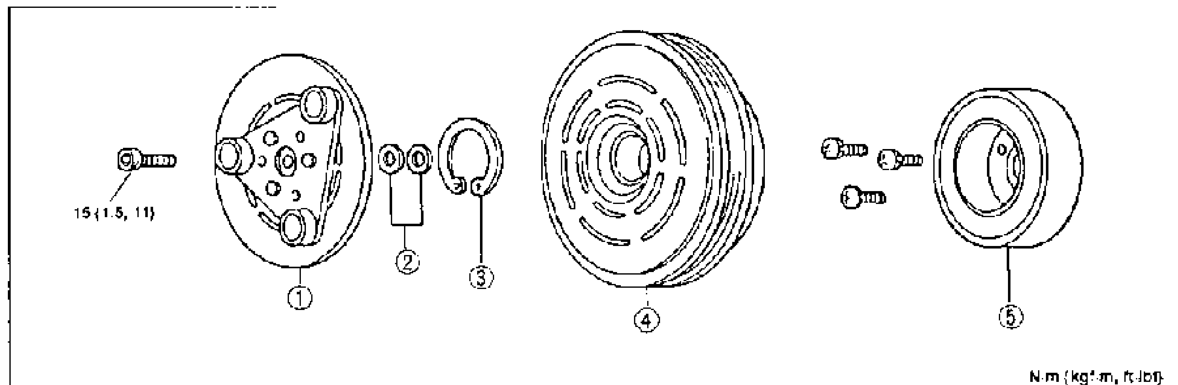
- 2Assemble in the reverse order of disassembly.
Parts DiagramFig. fig1
Assembly note
Pressure plate
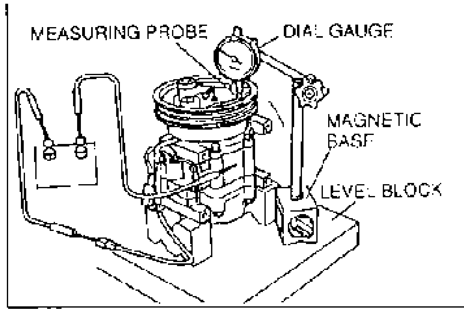
- 1Measure the clearance between the pressure plate and the rotor pulley. (1) Set the A/C compressor on a level block. (2) Fix a dial gauge on a magnetic base and set the measuring probe on the pressure plate surface. (3) Alternately apply and remove battery positive voltage as shown in the figure. The clearance is the difference in the dial gauge readings. (4) Compare the measured clearance with the specified clearance below.
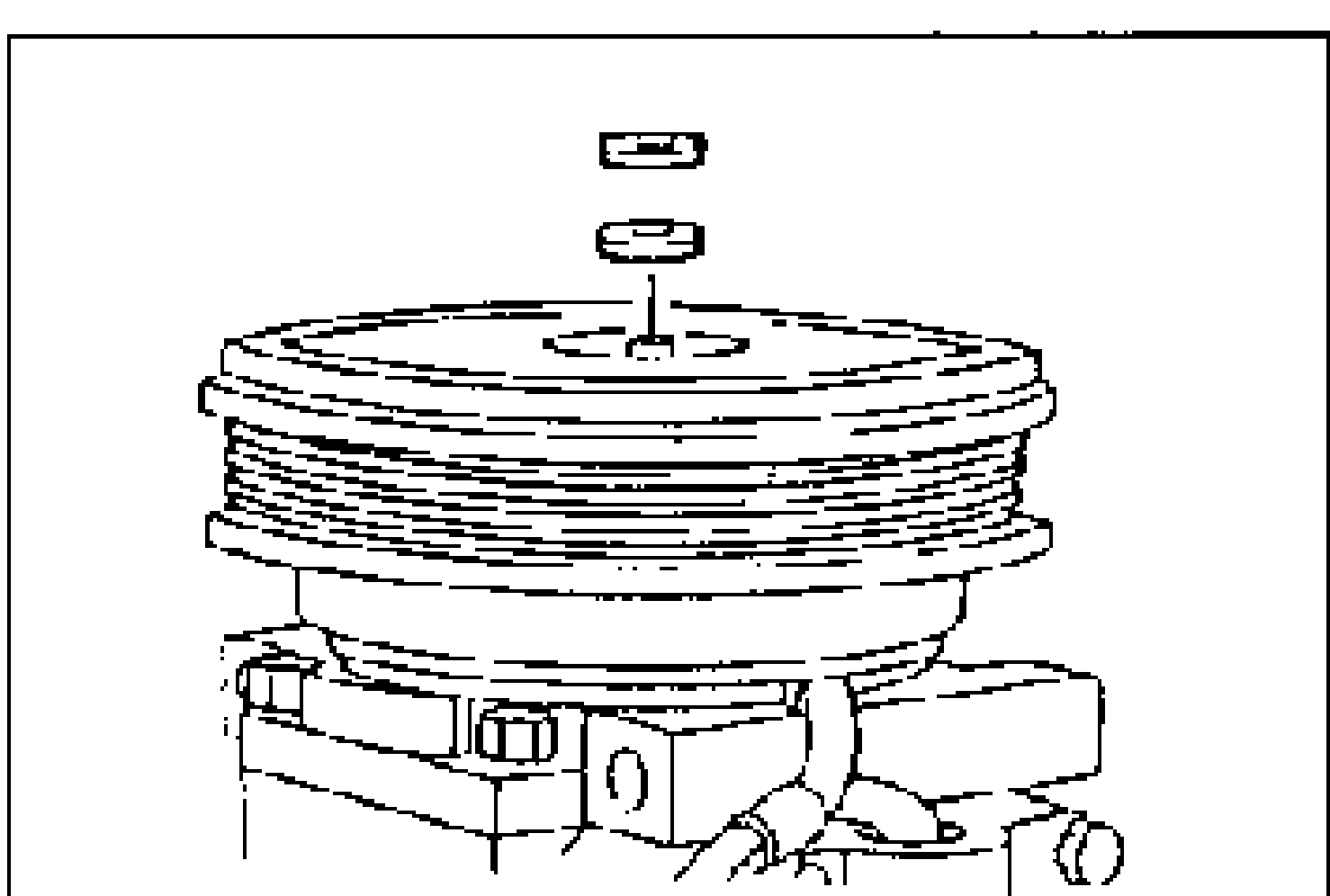
- 2If not as specified, install shims to adjust the clearance.
| Specification | Value |
|---|---|
| Clearancebetween pressure plate and rotor pulley | 0.4—0.5mm {0.016—0.020 in} |
Clearancebetween pressure plate and rotor pulley
0.4—0.5mm {0.016—0.020 in}
Shim
B455 61 L15
Thickness mm {in}0.2 {0.008}
B456 61 L15
Thickness mm {in}0.5 {0.020}
Inspection
Stator
- 1Set the ohmmeter to the × 1,000Ω range.
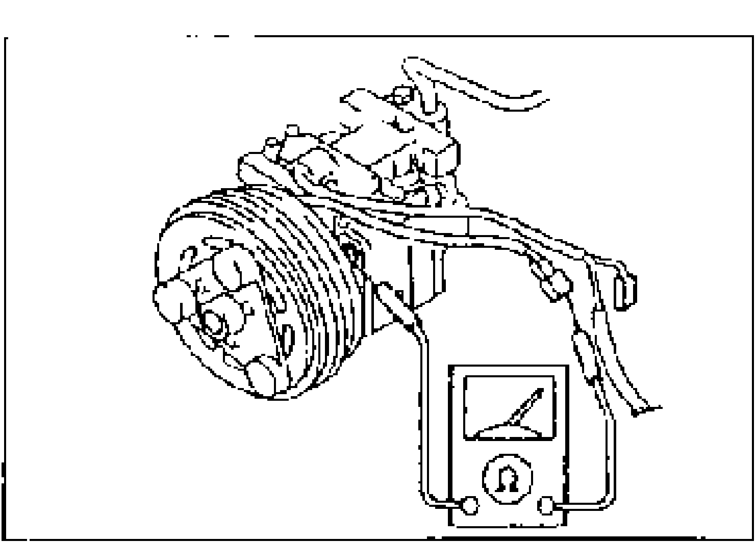
- 2Verify that there is continuity between the stator terminal and the A/C compressor body.
- 3If there is no continuity, replace the stator.