Mazda MX-3 silhouetteMX-3

REAR SHOCK ABSORBER AND SPRING — Removal / Installation

R-29parts diagram

Removal / Installation

  1. 1
    Jack up the rear of the vehicle and support it with safety stands.
  2. 2
    Remove the wheels.
  3. 3
    Remove the rear speaker cover and rear seat belt. (Refer to section S.)
  4. 4
    Remove in the order as shown in the figure.
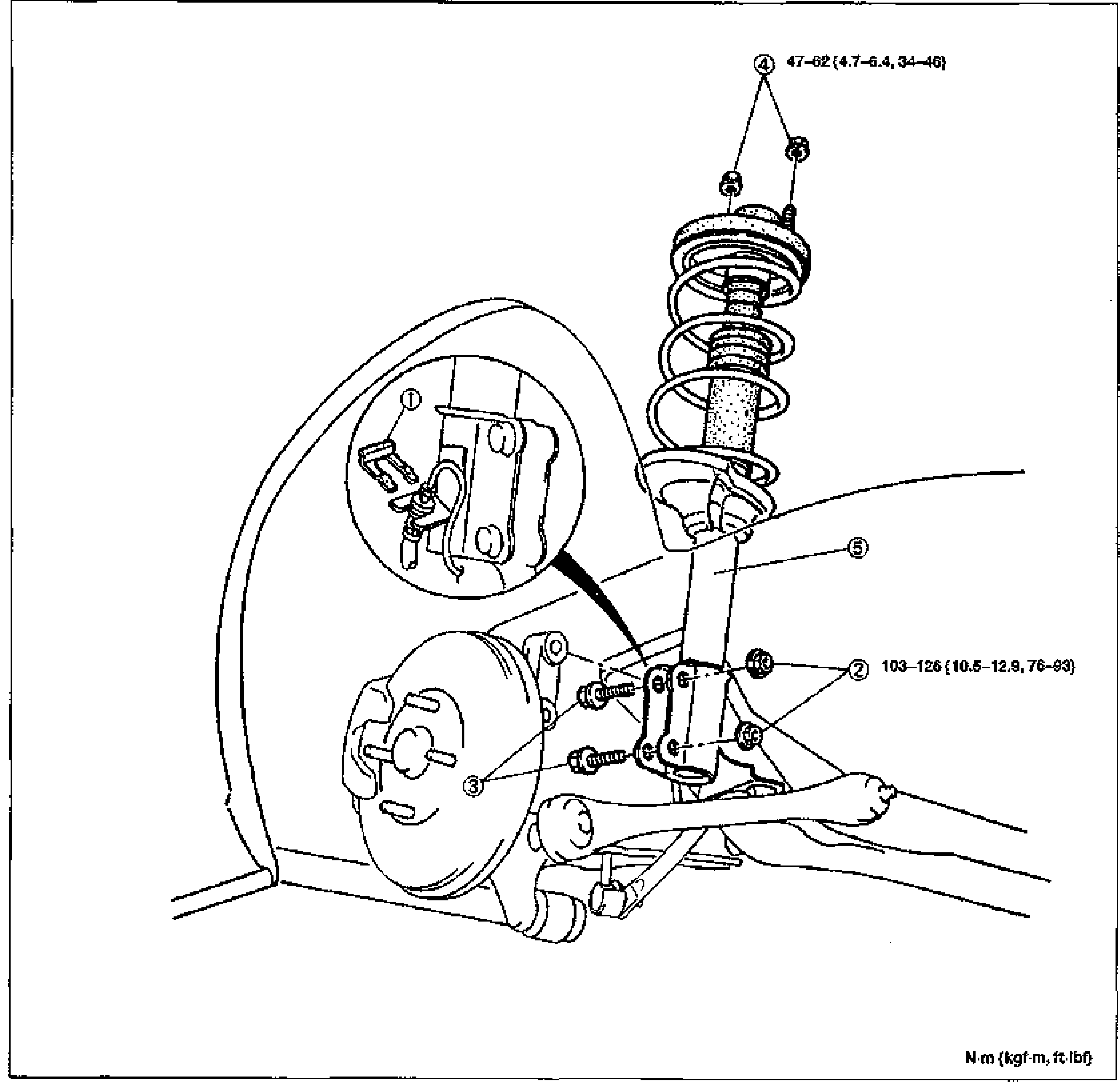
    Exploded view of the rear shock absorber and coil spring assembly with surrounding rear suspension (knuckle, brake drum/backing plate, lower arm). Numbered balloon callouts 1-5 with tightening torque values. Tightening torques shown: callout 4 nut 47-62 N·m {4.7-6.4 kgf·m, 34-46 ft·lbf}; callout 2 nut 103-126 N·m {10.5-12.9 kgf·m, 76-93 ft·lbf}. Torque legend N·m {kgf·m, ft·lbf} at bottom-right. Inset detail (top-left circle) shows the clip (1).
  5. 5
    Install in the reverse order of removal.
  6. 6
    Install the rear speaker cover and rear seat belt. (Refer to section S.)
  7. 7
    Install the wheels. (Tightening torque: 89-117 N·m {9.0-12.0 kgf·m, 66-86 ft·lbf})
  8. 8
    After installation, measure the rear wheel alignment, if necessary. (Refer to page R-9.)
Parts DiagramFig. fig1
#Part NameNotes
1Clip
2NutTightening torque 103-126 N·m {10.5-12.9 kgf·m, 76-93 ft·lbf}
3Bolt
4NutTightening torque 47-62 N·m {4.7-6.4 kgf·m, 34-46 ft·lbf}
5Shock absorber and springDisassembly / Inspection / Assembly ... page R-30

Search Manual

Search pages, specs, and procedures