Mazda MX-3 silhouetteMX-3

CLUTCH MASTER CYLINDER

H-11parts diagram

Overhaul

  1. 1
    Disassemble in the order shown in the figure, referring to Disassembly Note.
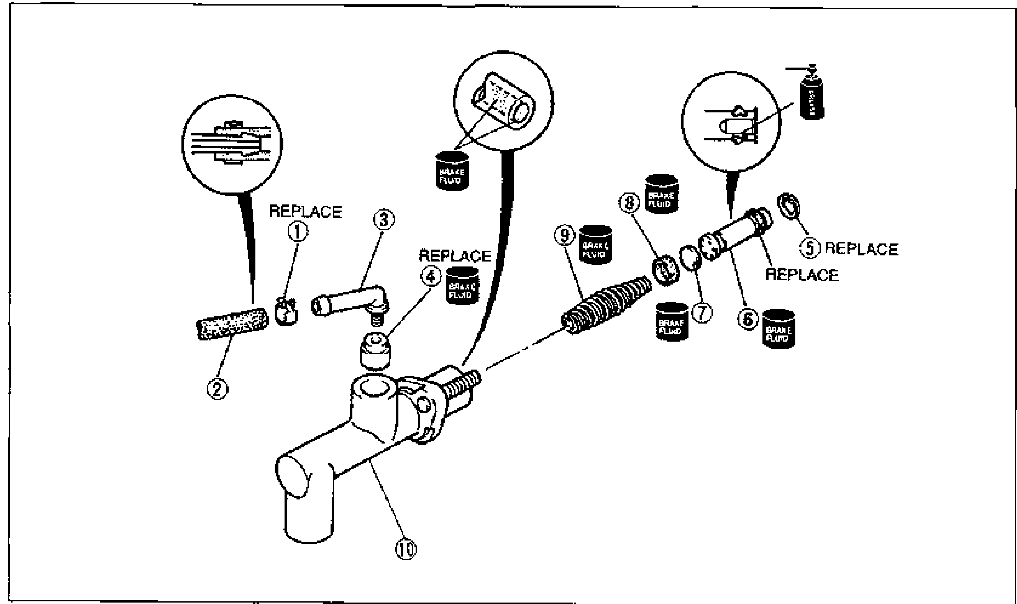
    Exploded view of the clutch master cylinder for overhaul. Numbered balloons 1-10 identify the clip, hose, joint, bushing, snap ring, piston and secondary cup assembly, spacer, primary cup, return spring and master cylinder body, shown in disassembly order along the cylinder bore axis. Inset detail circles show the clip engagement, bushing/joint and snap-ring fitting. Brake-fluid (clutch fluid) application symbols mark several internal parts; items (1), (4) and (5) marked REPLACE.
  2. 2
    Inspect all parts and repair or replace as necessary.
    Using compressed air can cause dirt and other particles to fly out, causing injury to the eyes. Wear protective eye wear whenever using compressed air.
  3. 3
    Wipe all parts, and clean all parts, passages, and inner parts with compressed air.
  4. 4
    Assemble in the reverse order of disassembly, referring to Assembly Note.
Parts DiagramFig. fig1
#Part NameNotes
1ClipReplace
2Hose
3Joint
4BushingReplace
5Snap ringReplace; Disassembly Note: below; Assembly Note: page H-12
6Piston and secondary cup assemblyDisassembly Note: page H-12; Assembly Note: page H-12; Inspect for wear, scoring and cracks
7Spacer
8Primary cupInspect for wear and cracks
9Return spring
10Master cylinder bodyInspect cylinder bore for scoring and corrosion

Disassembly Note

Snap ring

While holding the piston down with a cloth-wrapped pin punch, remove the snap ring.

See also

Search Manual

Search pages, specs, and procedures