
STARTING SYSTEM — STARTER Adjustment of pinion gap, No load test, Disassembly / Assembly
G-37prose procedureNo-load test specs differ by engine/transaxle: B6 DOHC, K8 DOHC (MTX), K8 DOHC (ATX). Disassembly exploded view is for K8 DOHC (MTX).
Adjustment of pinion gap
- 1Disconnect the wiring from terminal M.
- 2When the battery is connected between terminal S and the starter body, the pinion will be ejected and then stop. Measure the clearance (pinion gap) between the pinion and the stopper.Applying power continuously for more than 10 seconds will damage the starter.
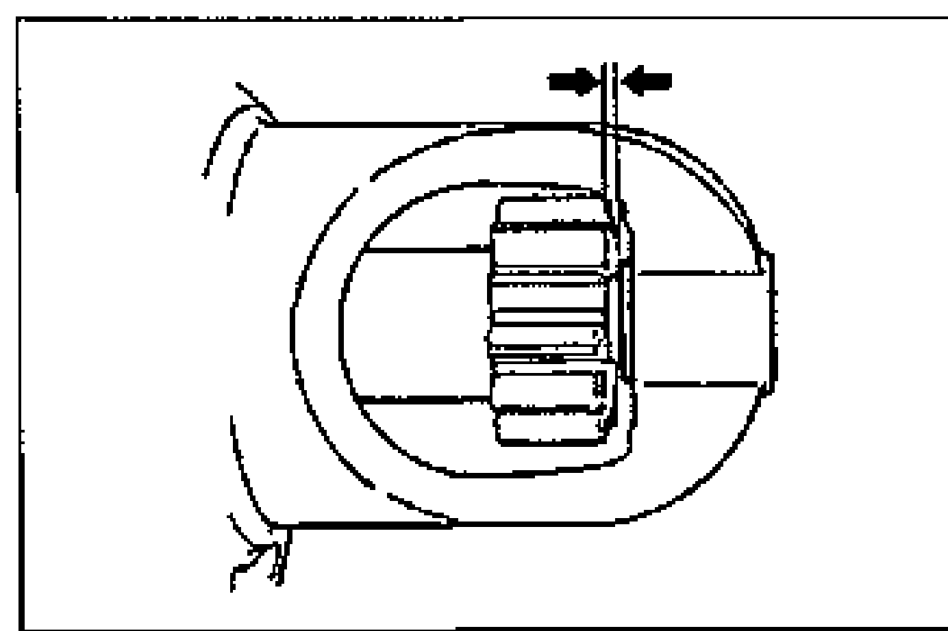
- 3If the pinion gap is not within the specification, make adjustment by increasing or decreasing the number of washers between the magnetic switch and the drive housing. (The gap becomes smaller as the number of washers is increased.)
CAUTION
Applying power continuously for more than 10 seconds will damage the starter.
| Specification | Value |
|---|---|
| Pinion gap | 0.5-2.0mm {0.020-0.078 in} |
Pinion gap
0.5-2.0mm {0.020-0.078 in}
No load test
- 1Connect the circuit as shown.
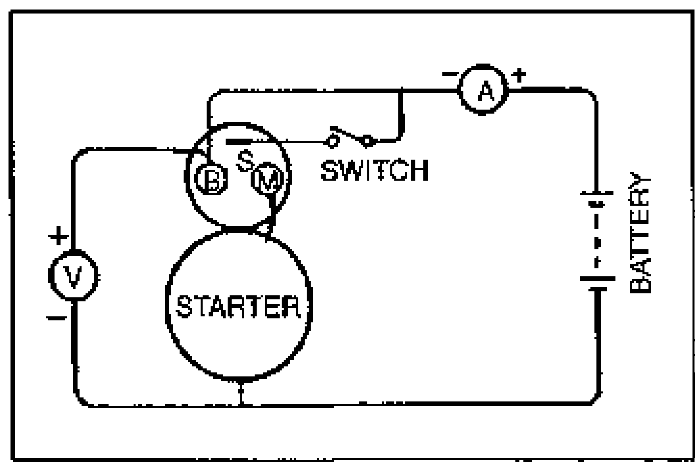
- 2Measure voltage, current, and speed as shown.
No load test specifications
Voltage (V)
B6 DOHC11
K8 DOHC (MTX)11
K8 DOHC (ATX)11
Current (A)
B6 DOHCbelow 50
K8 DOHC (MTX)below 90
K8 DOHC (ATX)below 70
Speed (rpm)
B6 DOHC5000 or higher
K8 DOHC (MTX)3000 or higher / 2900 or higher *1
K8 DOHC (ATX)2000 or higher / 2200 or higher *1
NOTE
*1: cold area
Disassembly / Assembly
- 1Disassemble in the order shown in the figure, referring to Disassembly Note.
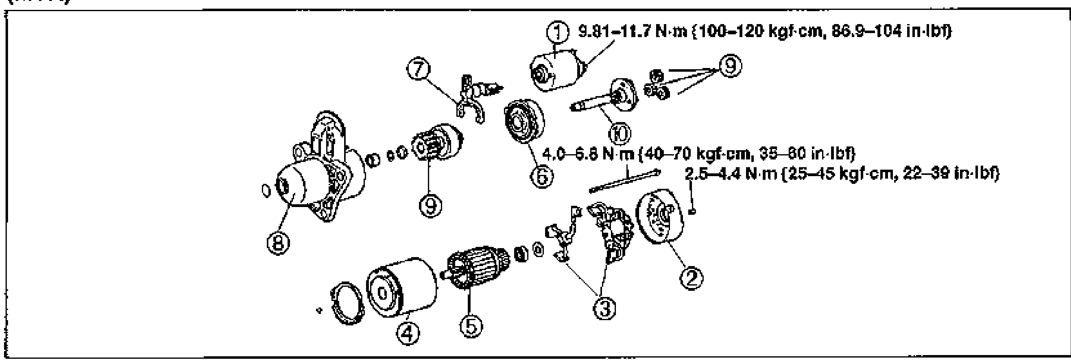
- 2Inspect all parts and repair or replace as necessary.
- 3Assemble in the reverse order of disassembly, referring to Assembly Note.
K8 DOHC (MTX)
Parts DiagramFig. fig3