Mazda MX-3 silhouetteMX-3

FRONT BUMPER

S-17parts diagram

COMPONENTS

Removal / Installation

  1. 1
    Disconnect the negative battery cable.
  2. 2
    Remove in the order shown in the figure. (Refer to the 1995 MX-3 Body Electrical Troubleshooting Manual, section E, when removing the front combination lights and front side marker lights.)
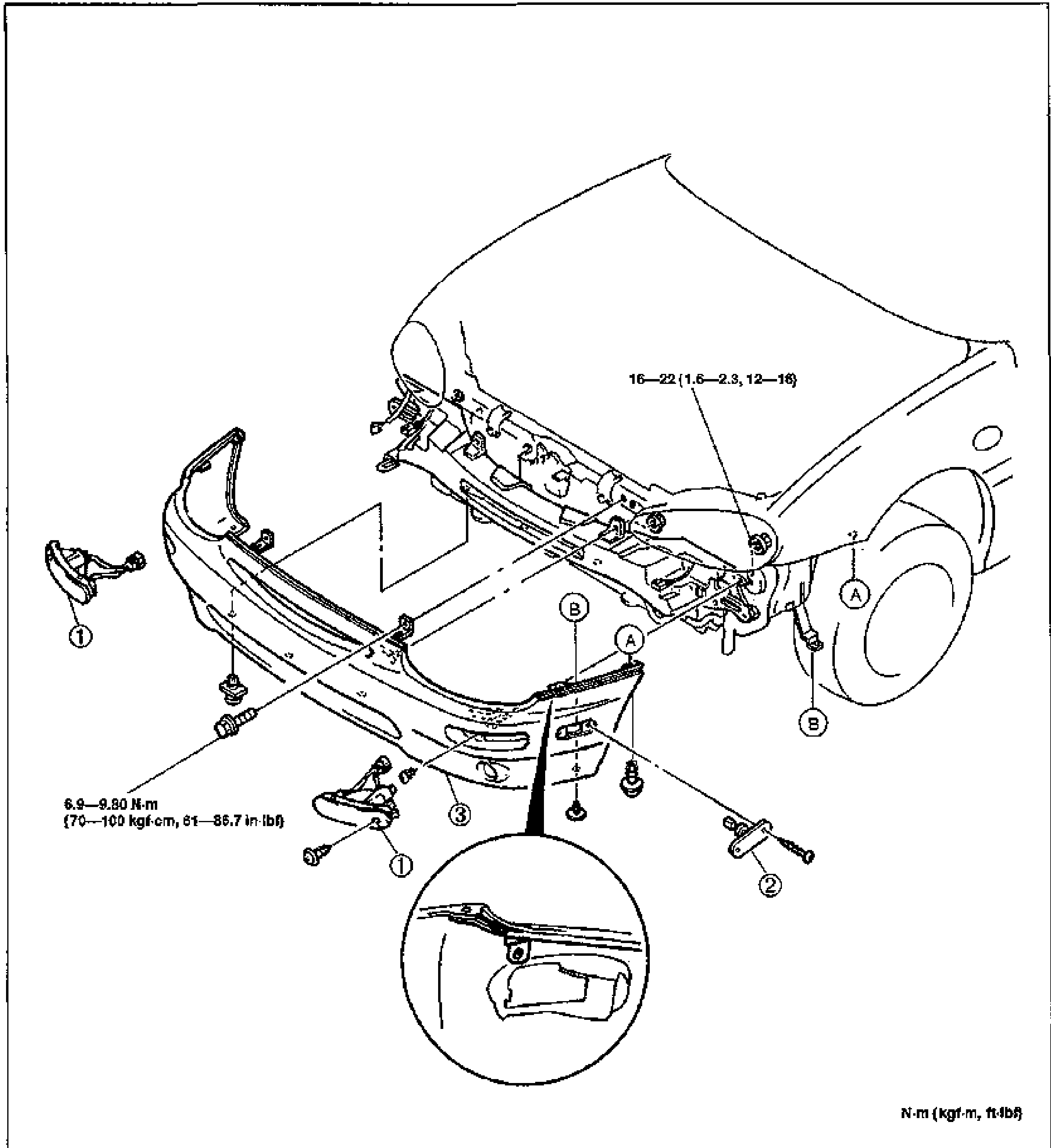
    Exploded view of the front bumper assembly on the front of the vehicle (hood/fender shown). Numbered balloon callouts 1-3 mark the front combination light, front side marker light and front bumper. Letter callouts A and B mark fastener locations. A circular detail inset at bottom shows a bumper bracket clip. Torque values: 16-22 N·m {1.6-2.3 kgf-m, 12-16 ft-lbf} at bracket bolts and 6.9-9.80 N·m {70-100 kgf-cm, 61-86.7 in-lbf} at the light mounting bolts. Units note at bottom right: N·m {kgf-m, ft-lbf}.
  3. 3
    Install in the reverse order of removal.
Parts DiagramFig. fig1
#Part NameNotes
1Front combination light
2Front side marker light
3Front bumperDisassembly / Assembly ... page S-18

See also

1995 MX-3 Body Electrical Troubleshooting Manual, section E

Search Manual

Search pages, specs, and procedures