Mazda MX-3 silhouetteMX-3

HEATER CONTROL UNIT - Disassembly / Assembly

G-44parts diagram

Diagram shows the LOGIC TYPE heater control unit.

Disassembly / Assembly

  1. 1
    Disassemble in the order shown in the figure.
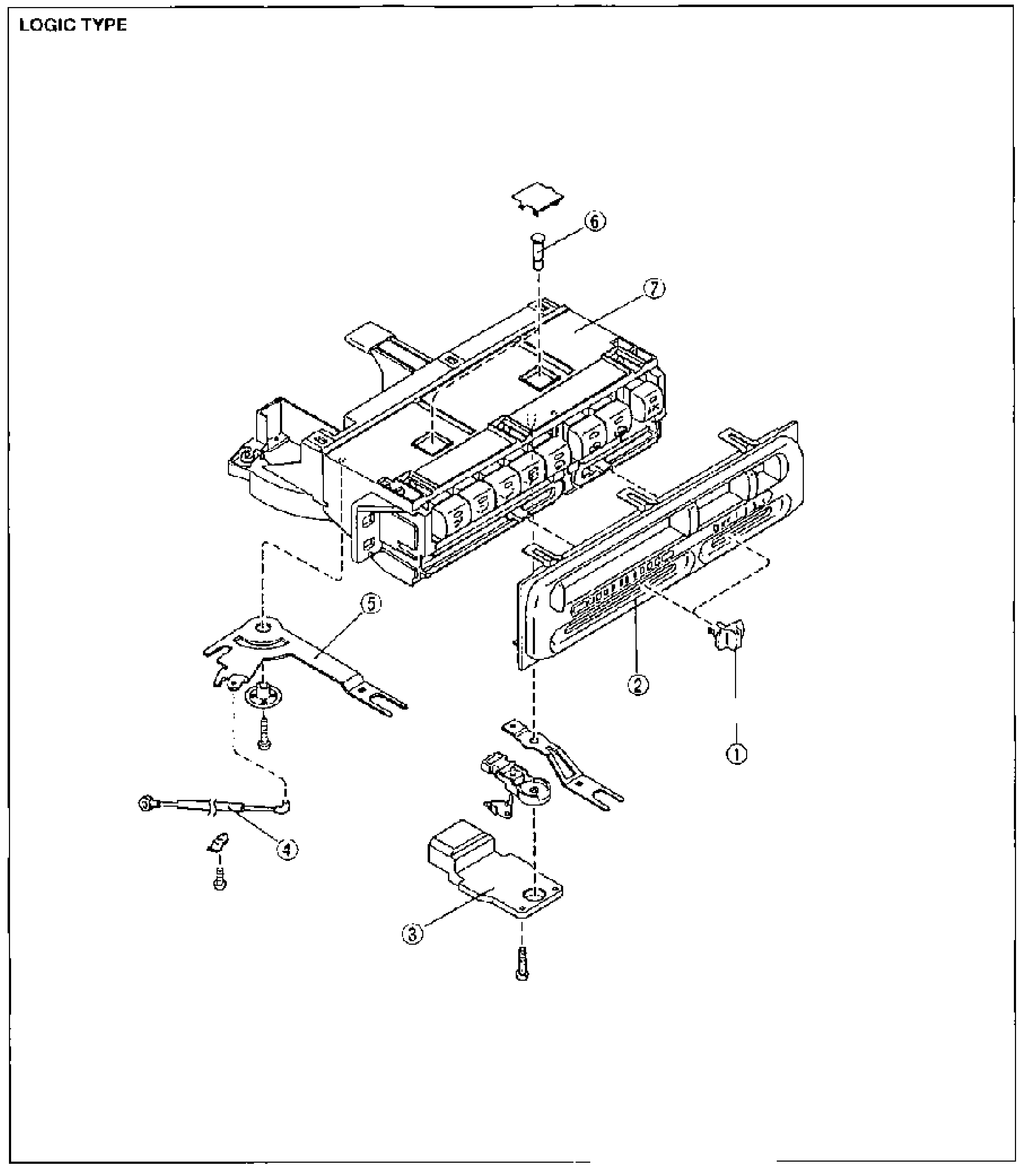
    Full-page exploded view of the LOGIC TYPE heater control unit disassembly. Balloon callouts: 1 = knob, 2 = switch panel, 3 = fan switch, 4 = air mix wire, 5 = temperature control lever, 6 = bulb, 7 = heater control unit (main body). Screws shown at mating points.
  2. 2
    Assemble in the reverse order of disassembly.
Parts DiagramFig. fig1
#Part NameNotes
1Knob
2Switch panel
3Fan switchInspection ... page G-46
4Air mix wireAdjustment ... page G-48
5Temperature control lever
6Bulb
7Heater control unitInspection ... page G-46

Search Manual

Search pages, specs, and procedures