
ANTI-LOCK BRAKE SYSTEM
P-72parts diagramABS RELAY
Removal / Inspection / Installation
- 1Disconnect the negative battery cable.
- 2Remove in the order shown in the figure.
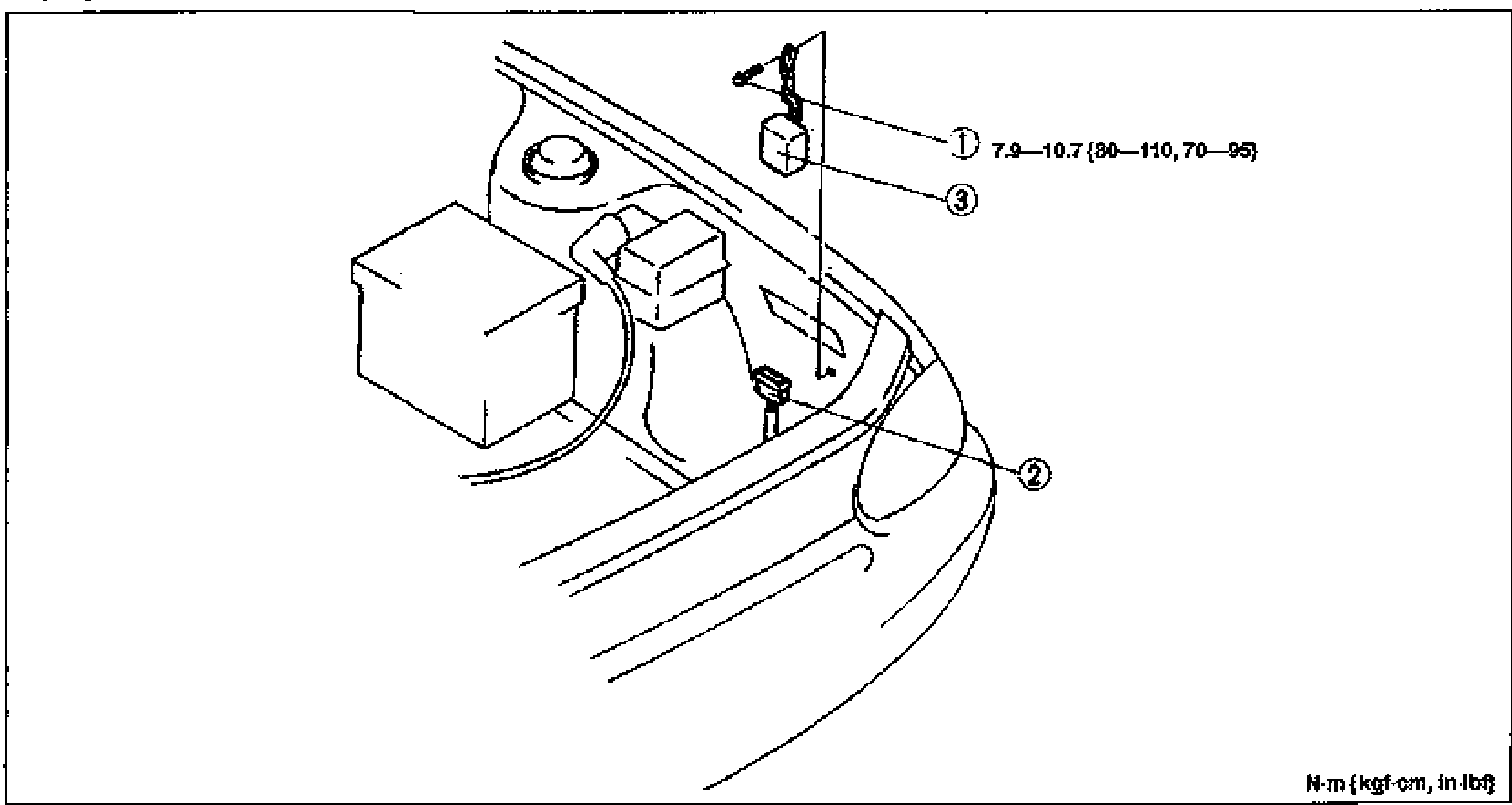
- 3Install in the reverse order of removal.
- 4Connect the negative battery cable, verify whether the diagnostic trouble code is canceled. (Refer to page P-56.)
Parts DiagramFig. fig1
Inspection - ABS relay (Fail-safe relay)
- 1Measure resistance between terminals (c) and (d) of the ABS relay connector.
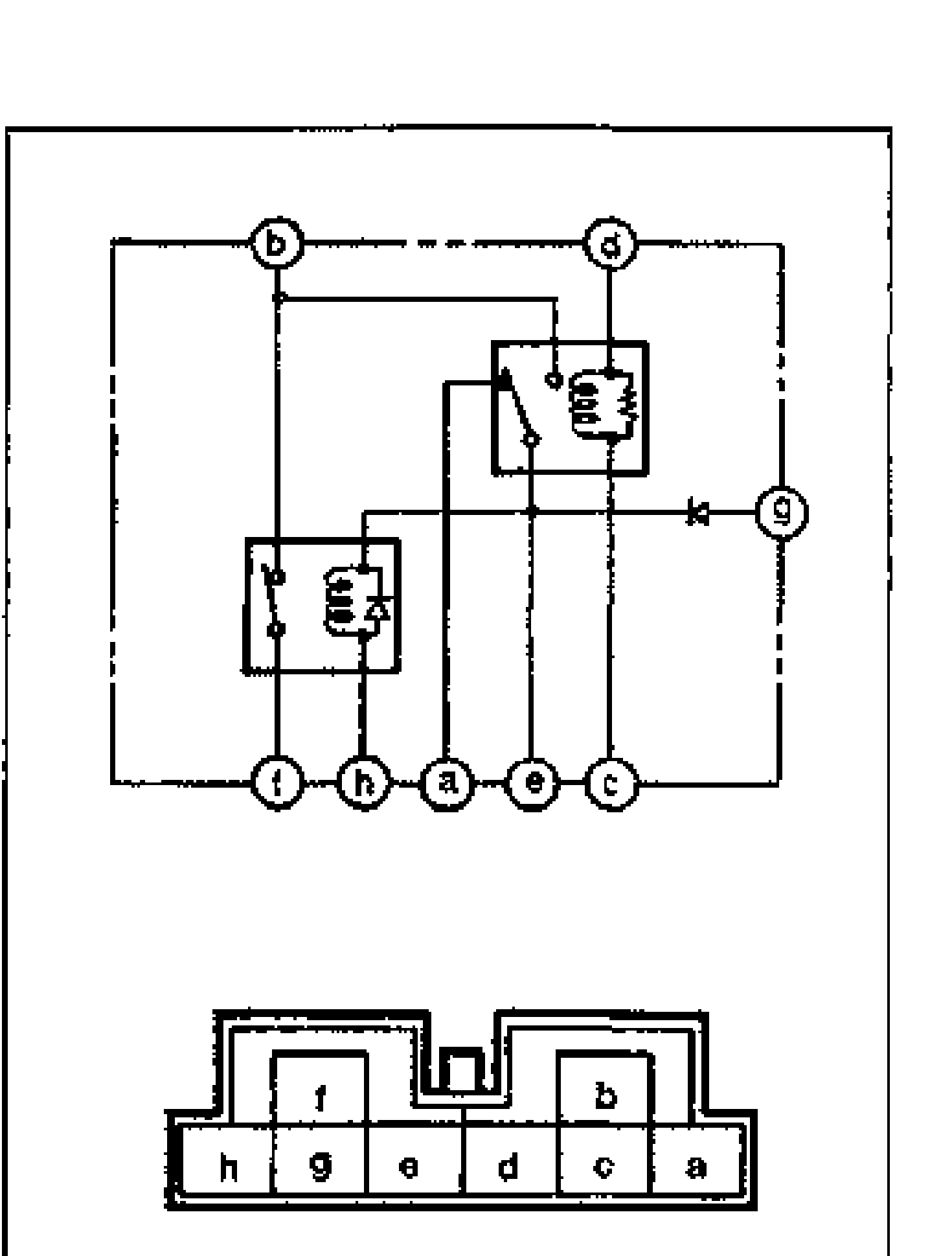
- 2Check continuity between terminals (a) and (e) and between (b) and (e).
- 3Apply 12V to terminals (d) and (c). Check for continuity between terminals (b) and (e) and between (a) and (e).
| Specification | Value |
|---|---|
| Resistancebetween terminals (c) and (d) | 60-100Ω |
Resistancebetween terminals (c) and (d)
60-100Ω
Continuity (no voltage applied)
a-e
ContinuityYes
b-e
ContinuityNo
Continuity (12V applied between d and c)
b-e
ContinuityYes
a-e
ContinuityNo