
FUEL INJECTOR
F2-115parts diagramExploded view shows the V6 (K8-ZE) twin fuel distributor (right and left bank) arrangement.
Inspection (On-vehicle)
- 1Warm up the engine and run it at idle.
- 2Listen for the operational sound of each fuel injector by using a screwdriver or a soundscope.The best way to judge the performance of a fuel injector is to compare its sound with the sound of other fuel injectors.
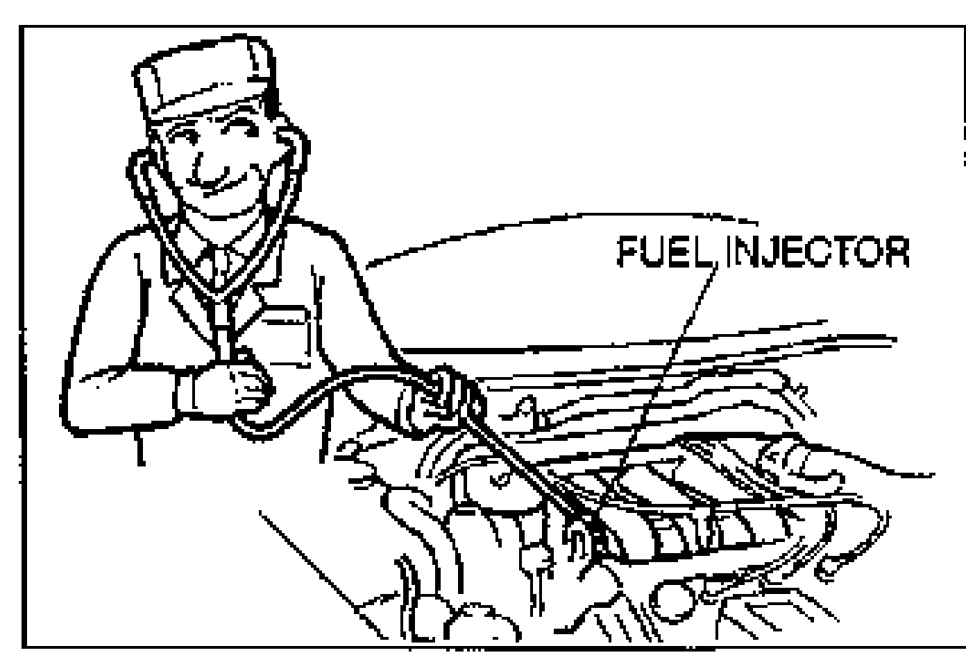
NOTE
The best way to judge the performance of a fuel injector is to compare its sound with the sound of other fuel injectors.
Removal / Installation
WARNING
Fuel line spills and leaks are dangerous. Fuel can ignite and cause serious injuries or death and damage. Fuel can also irritate skin and eyes. To prevent this, always complete the "Fuel Line Safety Procedures" on page F2-106.
Removal / Installation
- 1Remove in the order shown in the figure.
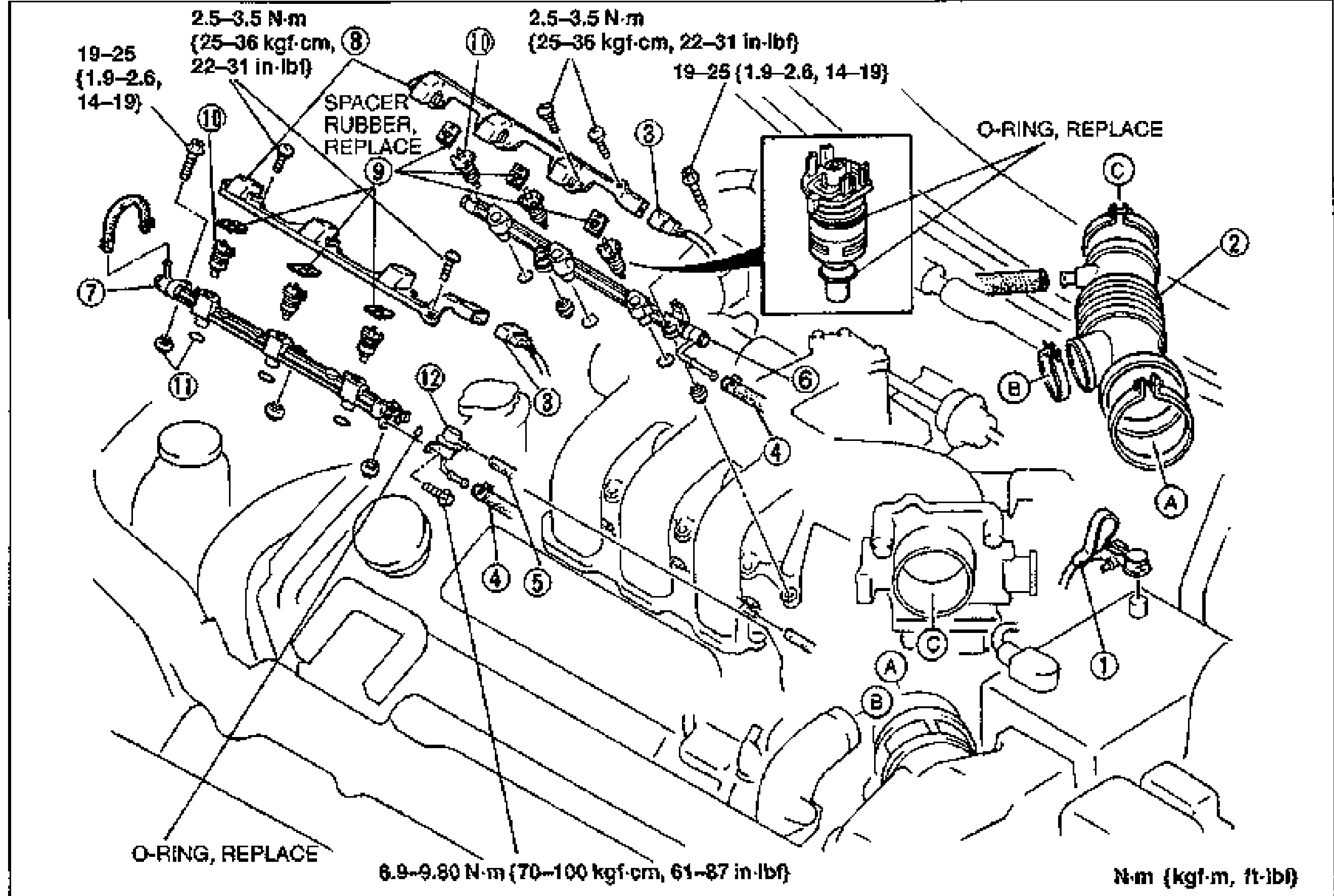
- 2Install in the reverse order of removal, referring to Installation Note.
Parts DiagramFig. fig2
| Specification | Value |
|---|---|
| Tightening torque (item 8/10 bolts) | 2.5 - 3.5N·m |
| Tightening torque (fuel distributor) | 19 - 25N·m |
| 8.9 - 9.80N·m |
Tightening torque (item 8/10 bolts)
2.5 - 3.5N·m
Tightening torque (fuel distributor)
19 - 25N·m
8.9 - 9.80N·m