
CHARGING SYSTEM - GENERATOR Removal / Installation (B6 DOHC)
G-12parts diagramGenerator removal/installation shown for B6 DOHC engine.
GENERATOR - Removal / Installation
WARNING
When the battery cables are connected, touching the vehicle body with generator terminal B will generate sparks. This can cause personal injury, fire, and damage to the electrical components. Always disconnect the battery before performing the following operation.
CAUTION
Reversing the battery connections or using high-voltage testers will damage the rectifier.
Do not start the engine while the connector is disconnected from terminals L and S. It can damage the generator.
NOTE
Battery positive voltage is always present at generator terminal B when the battery is connected.
Removal / Installation
- 1Disconnect the negative battery cable.
- 2Remove in the order shown in the figure.
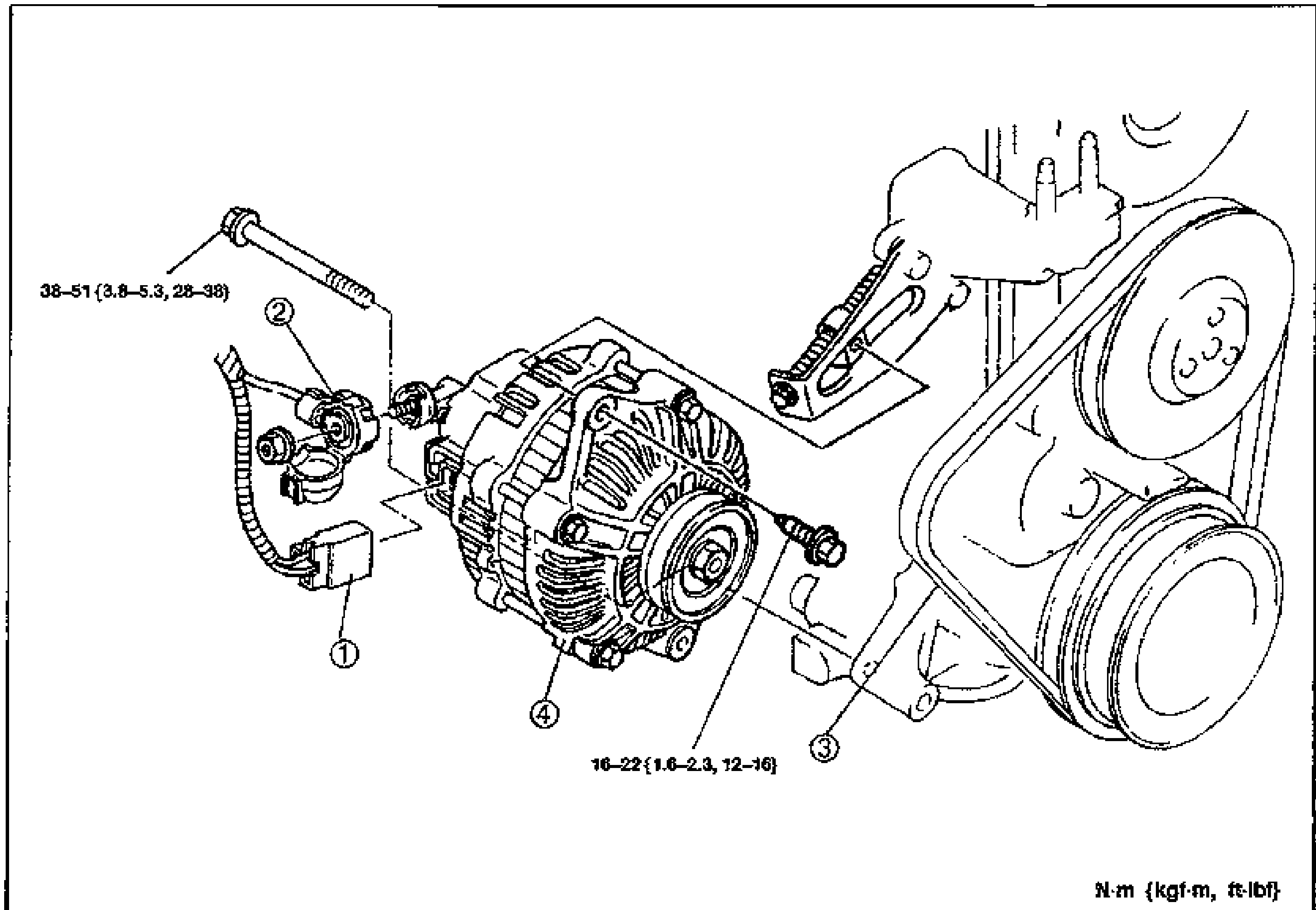
- 3Inspect all parts and repair or replace as necessary.
- 4Install in the reverse order of removal.
B6 DOHC
Parts DiagramFig. fig1