KNOCK SENSOR
F2-156parts diagramCONTROL SYSTEM
KNOCK SENSOR
Removal / Installation
WARNING
Fuel line spills and leaks are dangerous. Fuel can ignite and cause serious injuries or death and damage. Fuel can also irritate skin and eyes. To prevent this, always complete the "Fuel Line Safety Procedures" on page F2-106.
Knock Sensor Removal / Installation
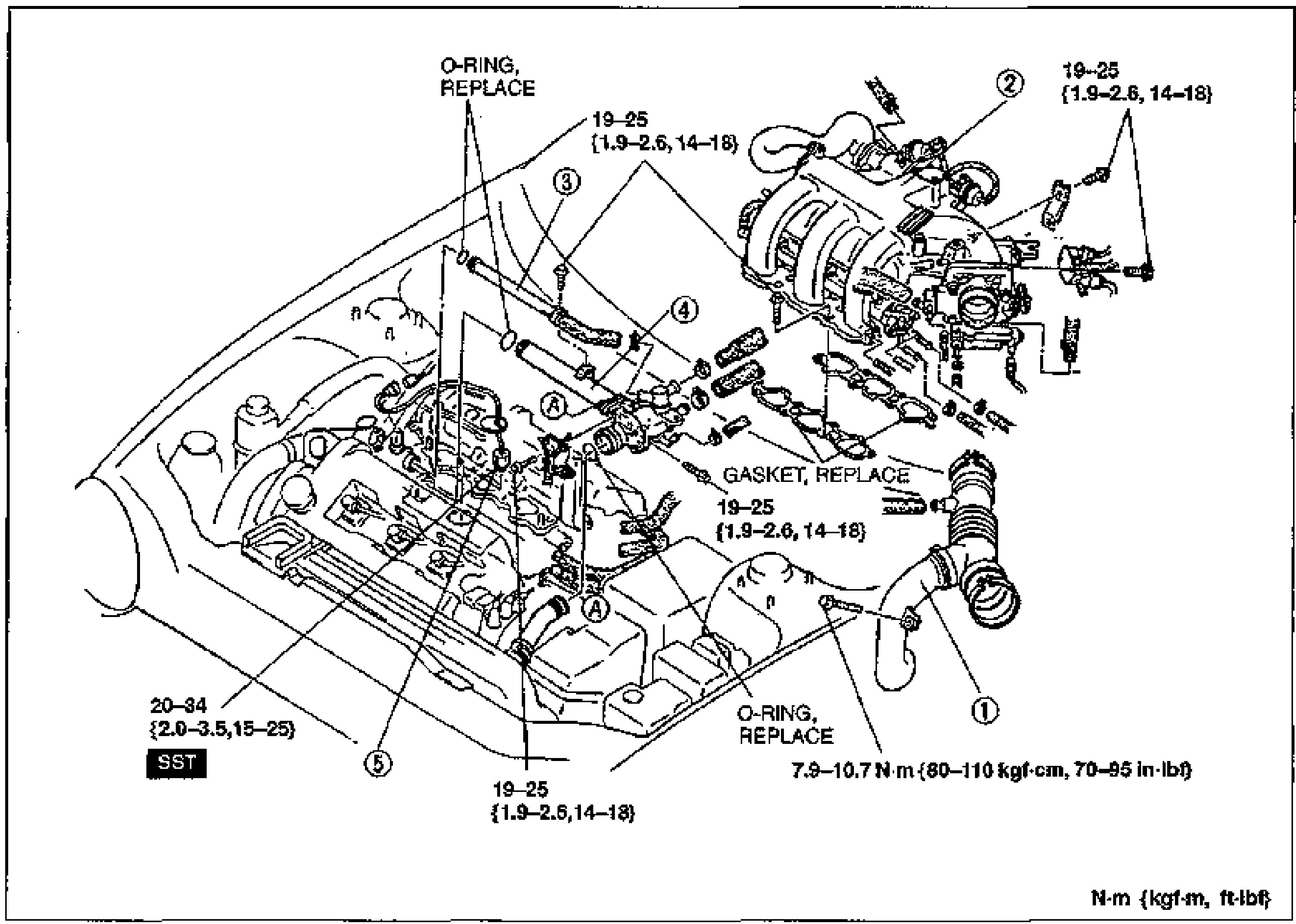
- 1Remove in the order shown in the figure, referring to Removal Note.
- 2Inspect the fuel tank components visually and repair or replace as necessary.
- 3Install in the reverse order of removal, referring to Installation Note.
Parts DiagramFig. fig1
Removal / Installation Note
Engine coolant
Removal / Installation Note - Engine coolant
- 1Drain the engine coolant into a container before removing the intake manifold.
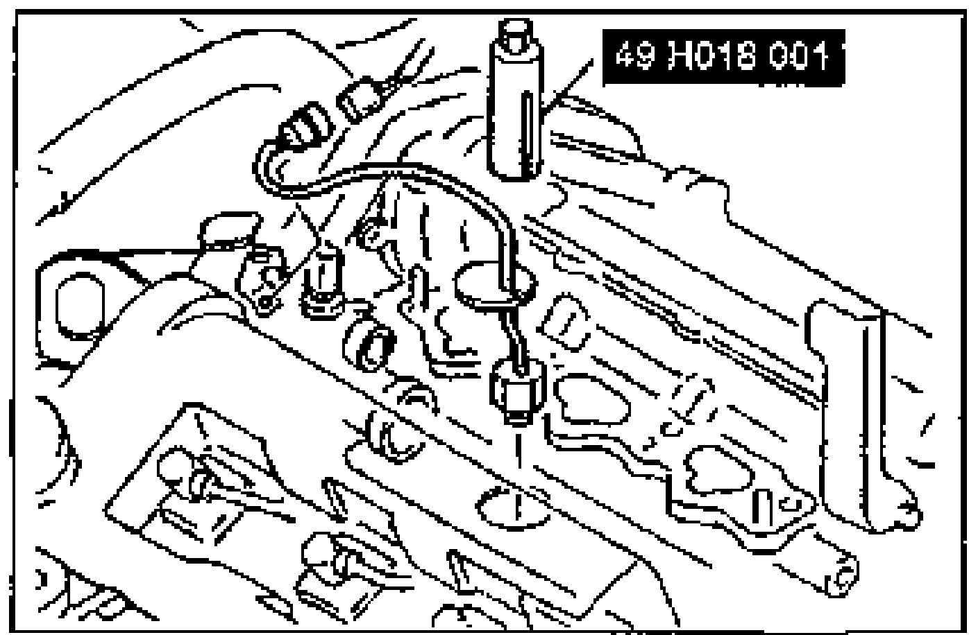
- 2Use the SST to remove / install the knock sensor.