Mazda MX-3 silhouetteMX-3

DRIVE SHAFT

M-22parts diagram

Dust cover parts 1 and 2 are specific to K8 DOHC; the exploded view shows separate dust cover/bracket geometry for K8 DOHC and B6 DOHC.

Disassembly / Inspection / Assembly

  1. 1
    Disassemble in the order shown in the figure, referring to Disassembly Note.
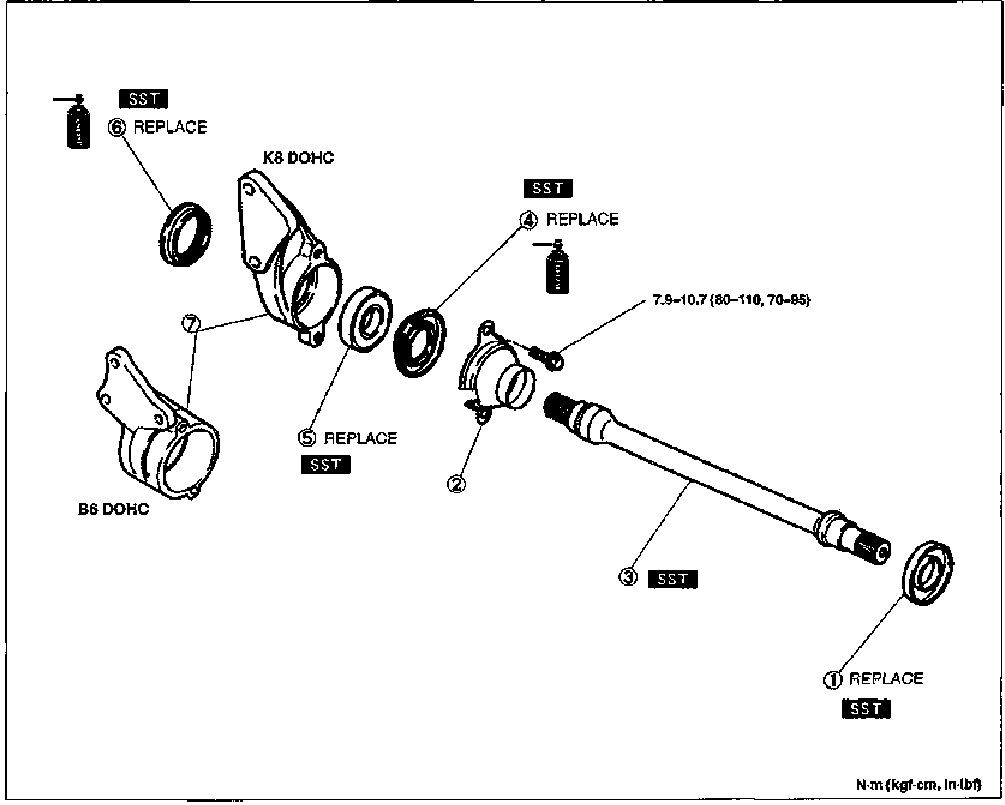
    Exploded view of the joint shaft disassembly/inspection/assembly with numbered balloon callouts 1-7. Shows the dust cover differential side for K8 DOHC and B6 DOHC variants, dust seals, bearing, joint shaft, and bracket. Several parts are marked REPLACE and SST. A bolt torque of 7.9-10.7 N·m {80-110 kgf·cm, 70-95 in·lbf} is annotated. Units: N·m {kgf·cm, in·lbf}.
  2. 2
    Inspect all parts and repair or replace as necessary.
  3. 3
    Assemble in the reverse order of disassembly, referring to Assembly Note.
Parts DiagramFig. fig1
#Part NameNotes
1Dust cover (differential side, K8 DOHC)Disassembly Note below; Assembly Note page M-24
2Dust cover (bracket side, K8 DOHC)
3Joint shaftInspect splines for damage and wear; Disassembly Note page M-23; Assembly Note page M-24
4Dust seal (differential side)Disassembly Note page M-23; Assembly Note page M-24
5BearingDisassembly Note page M-23; Assembly Note page M-23
6Dust seal (drive shaft side)Assembly Note page M-23
7Bracket

Disassembly Note

Dust cover (differential side, K8 DOHC)

While holding the joint shaft, press out the dust cover by using the SST.

Search Manual

Search pages, specs, and procedures