Mazda MX-3 silhouetteMX-3

REAR BUMPER

S-19parts diagram

COMPONENTS

Removal / Installation

  1. 1
    Disconnect the negative battery cable.
  2. 2
    Remove in the order shown in the figure. (Refer to the 1995 MX-3 Body Electrical Troubleshooting Manual, section E, when removing the rear combination lights.)
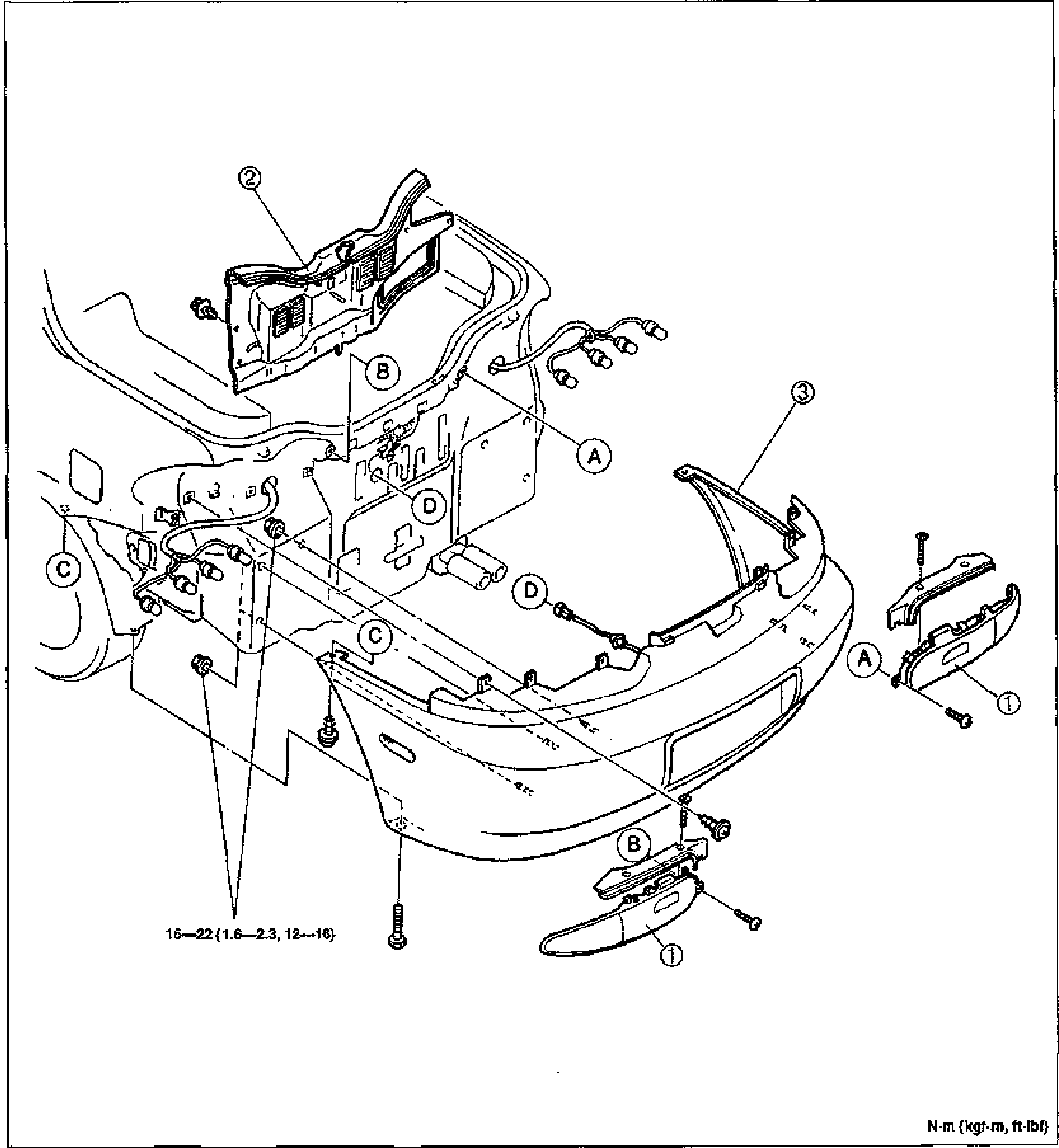
    Exploded view of the rear bumper assembly on the rear of the vehicle. Numbered balloon callouts 1-3 mark the rear combination light, trunk end trim and rear bumper. Letter callouts A, B, C, D mark fastener and clip attachment points around the bumper and rear body. Torque value 16-22 N·m {1.6-2.3 kgf-m, 12-16 ft-lbf} called out at bumper mounting bolts. Units note at bottom right: N·m {kgf-m, ft-lbf}.
  3. 3
    Install in the reverse order of removal.
Parts DiagramFig. fig1
#Part NameNotes
1Rear combination light
2Trunk end trimRemoval / Installation ... page S-65
3Rear bumperDisassembly / Assembly ... page S-20

See also

1995 MX-3 Body Electrical Troubleshooting Manual, section E

Search Manual

Search pages, specs, and procedures