Mazda MX-3 silhouetteMX-3

ENGINE SPEED SENSING POWER STEERING — Boot Removal / Installation

N-17parts diagram

BOOT

Removal / Installation

  1. 1
    Remove in the order shown in the figure, referring to Removal Note.
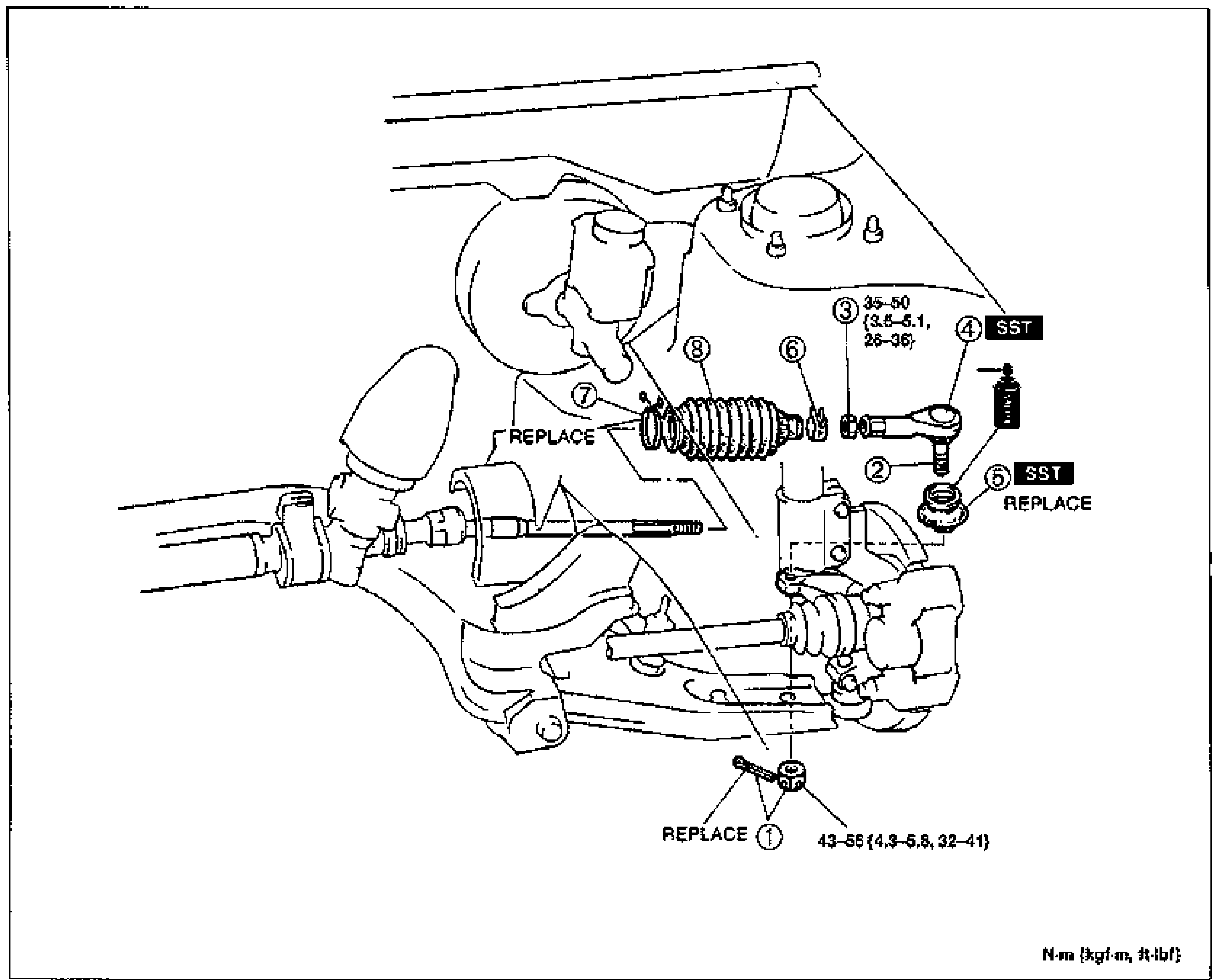
    Exploded view of the front suspension / steering tie-rod and boot assembly. Numbered balloon callouts (1-8) identify the cotter pin & nut, tie-rod end ball joint, locknut, tie-rod end, tie-rod end boot, boot band, boot wire, and rack boot. Tightening torque annotations appear at callout 3 (35-50 N·m {3.6-5.1 m-kgf, 26-36 ft-lbf}) and at callout 1 (43-58 N·m {4.3-5.9 m-kgf, 32-41 ft-lbf}). 'SST' tool boxes are shown at callouts 4 and 5. 'REPLACE' labels mark the cotter pin (1), rack boot (7) and tie-rod end boot (5). Units note: N·m {kgf·m, ft-lbf}.
  2. 2
    Install in the reverse order of removal, referring to Installation Note.
  3. 3
    Check the front wheel alignment. (Refer to Section R.)
Parts DiagramFig. fig1
#Part NameNotes
1Cotter pin, nutREPLACE; tightening torque 43-58 N·m {4.3-5.9 m-kgf, 32-41 ft-lbf}
2Tie-rod end ball jointRemoval Note: below
3LocknutRemoval Note: page N-18; tightening torque 35-50 N·m {3.6-5.1 m-kgf, 26-36 ft-lbf}
4Tie-rod endSST
5Tie-rod end bootRemoval Note: page N-18; Installation Note: page N-18; SST; REPLACE
6Boot band
7Boot wire
8Rack bootREPLACE

Removal Note

Tie-rod end ball joint

Disconnect the tie-rod end ball joint by using the SST.

Search Manual

Search pages, specs, and procedures