
ANTI-LOCK BRAKE SYSTEM
P-71parts diagramInstallation Note - ABS hydraulic unit
- 1Clamp the harness to point A of the bracket.
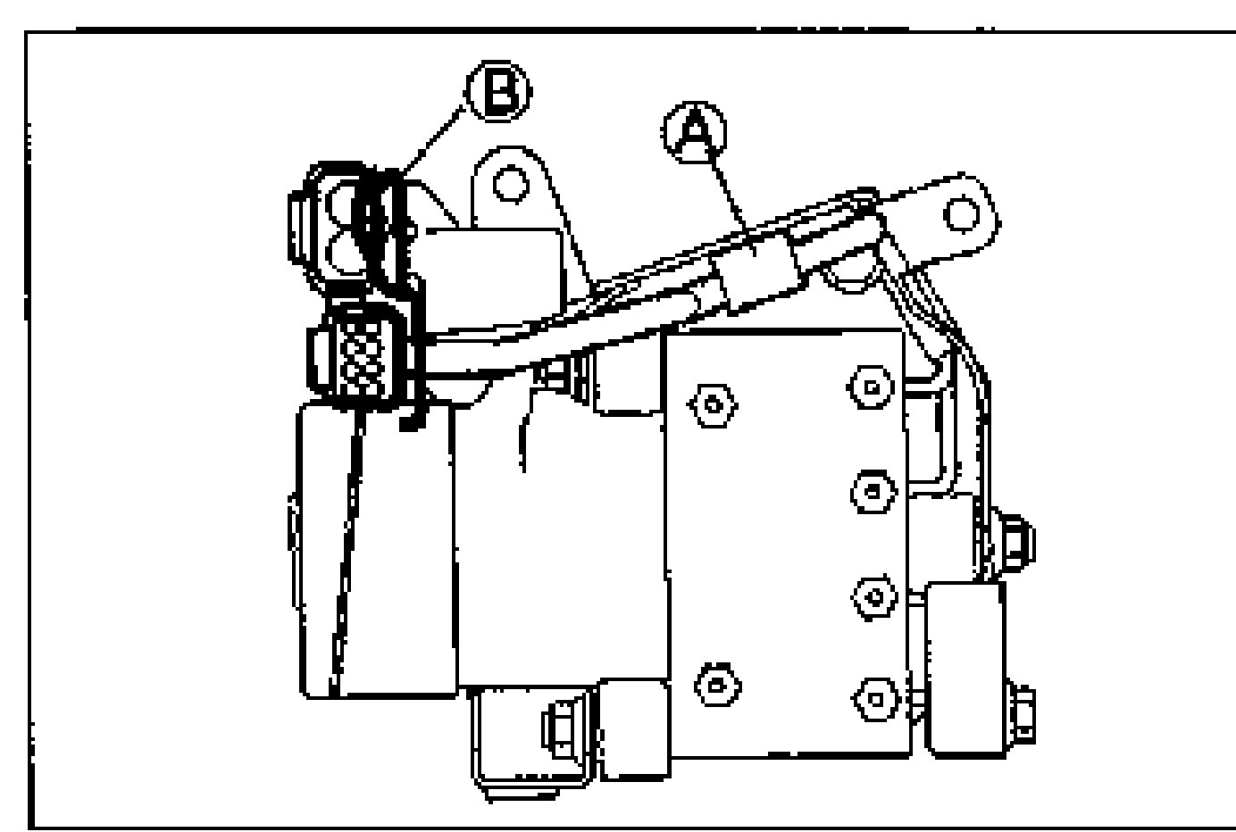
- 2Install the band around point B of the bracket and the harness, and tighten the band until it contacts the bracket.
- 3Cut off the rest of the band end so that the rest of band notches are less than seven.
Brake pipes
Tighten the brake pipe by using the SST.
| Specification | Value |
|---|---|
| brake pipe | 13 - 22N·m |
brake pipe
13 - 22N·m
ABS CONTROL MODULE
Removal / Installation
- 1Disconnect the negative battery cable.
- 2Remove the passenger seat.
- 3Roll back the carpet.
- 4Remove in order shown in the figure.
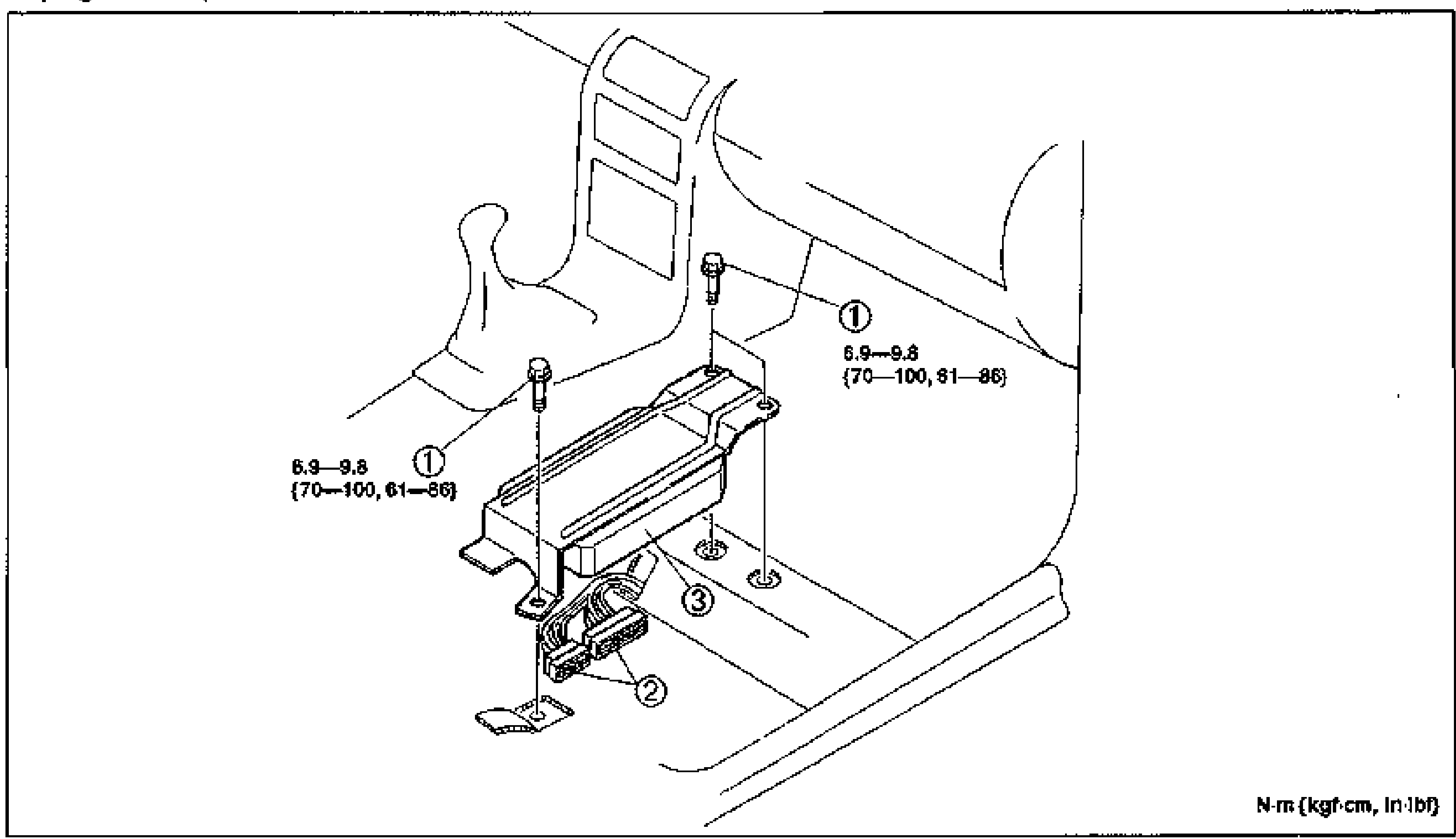
- 5Install in the reverse order of removal.
- 6Connect the negative battery cable, verify whether the diagnostic trouble code is canceled. (Refer to page P-56.)
Parts DiagramFig. fig3