Mazda MX-3 silhouetteMX-3

Conventional Brake System — Caliper Disassembly / Inspection / Assembly

P-35parts diagram

CALIPER

Disassembly / Inspection / Assembly

Caliper Disassembly / Inspection / Assembly

  1. 1
    Disassemble in the order shown in the figure, referring to Disassembly Note.
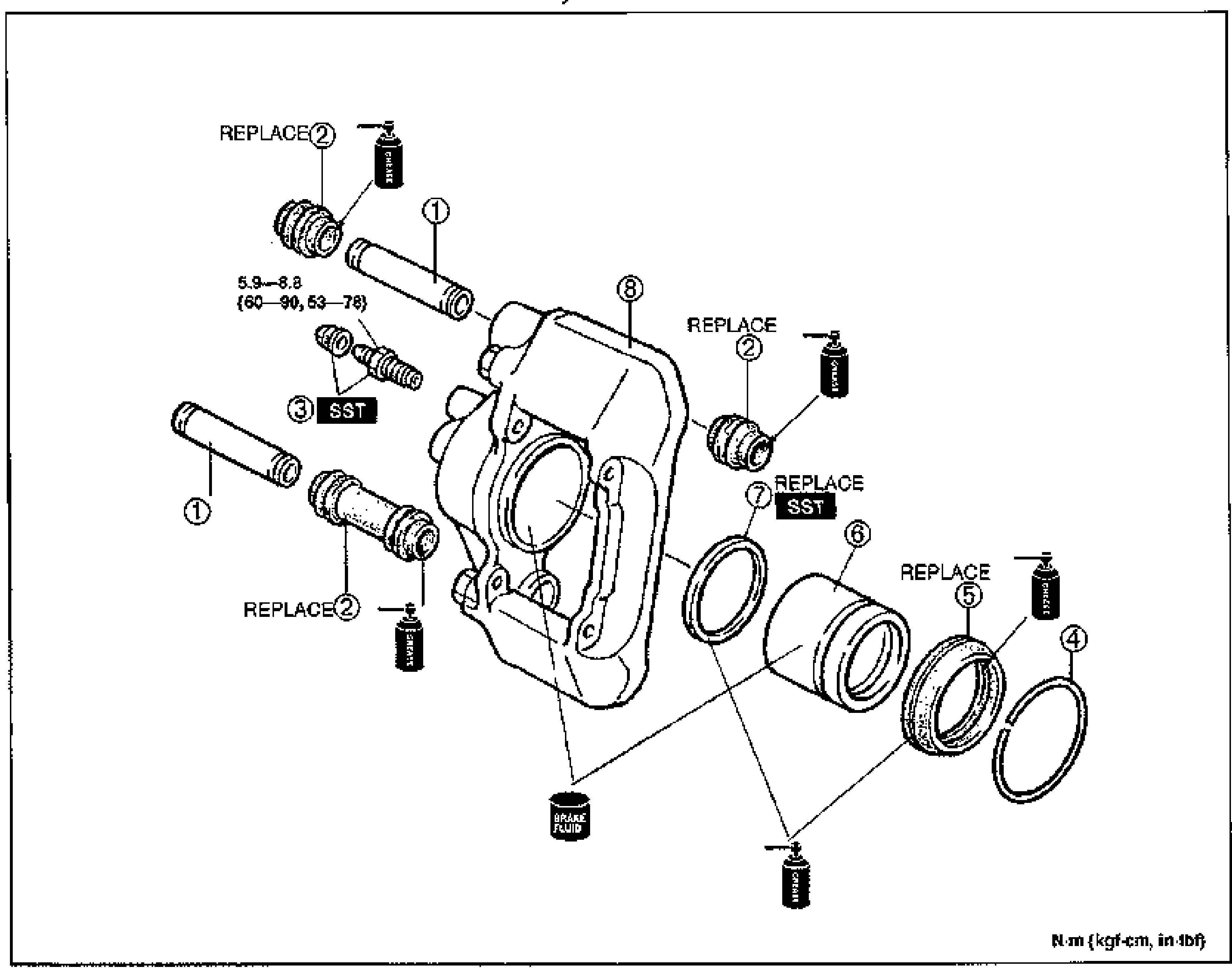
    Exploded view of the brake caliper assembly with numbered balloon callouts 1-8: sleeve pins, boots (marked REPLACE), rubber cap and bleeder screw (marked SST), retaining ring, dust seal, piston, piston seal (marked REPLACE, SST) and caliper body. Grease and brake-fluid application icons are shown at several joints. Tightening torque label points to the sleeve pin: 5.9-8.8 N·m {60-90, 53-78}. Unit note bottom-right: N·m (kgf·cm, in-lbf).
  2. 2
    Inspect all parts and repair or replace as necessary.
  3. 3
    Assemble in the reverse order of disassembly.
Parts DiagramFig. fig1
#Part NameNotes
1Sleeve pin
2Boot
3Rubber cap and bleeder screwbelow
4Retaining ring
5Dust seal
6PistonDisassembly Note ... page P-36; Inspect for damage, wear and rust
7Piston sealDisassembly Note ... page P-36
8Caliper bodyInspect for damage, wear and rust

Disassembly Note

Rubber cap and bleeder screw

Remove the rubber cap and remove the bleeder screw from the brake caliper by using the SST.

See also

Search Manual

Search pages, specs, and procedures