Mazda MX-3 silhouetteMX-3

CONVENTIONAL BRAKE SYSTEM - Brake Pedal Removal / Inspection / Installation

P-11parts diagram

Figure includes MTX (manual transmission) and ATX (automatic transmission) brake pedal pad variants.

Removal / Inspection / Installation

  1. 1
    Remove in the order shown in the figure.
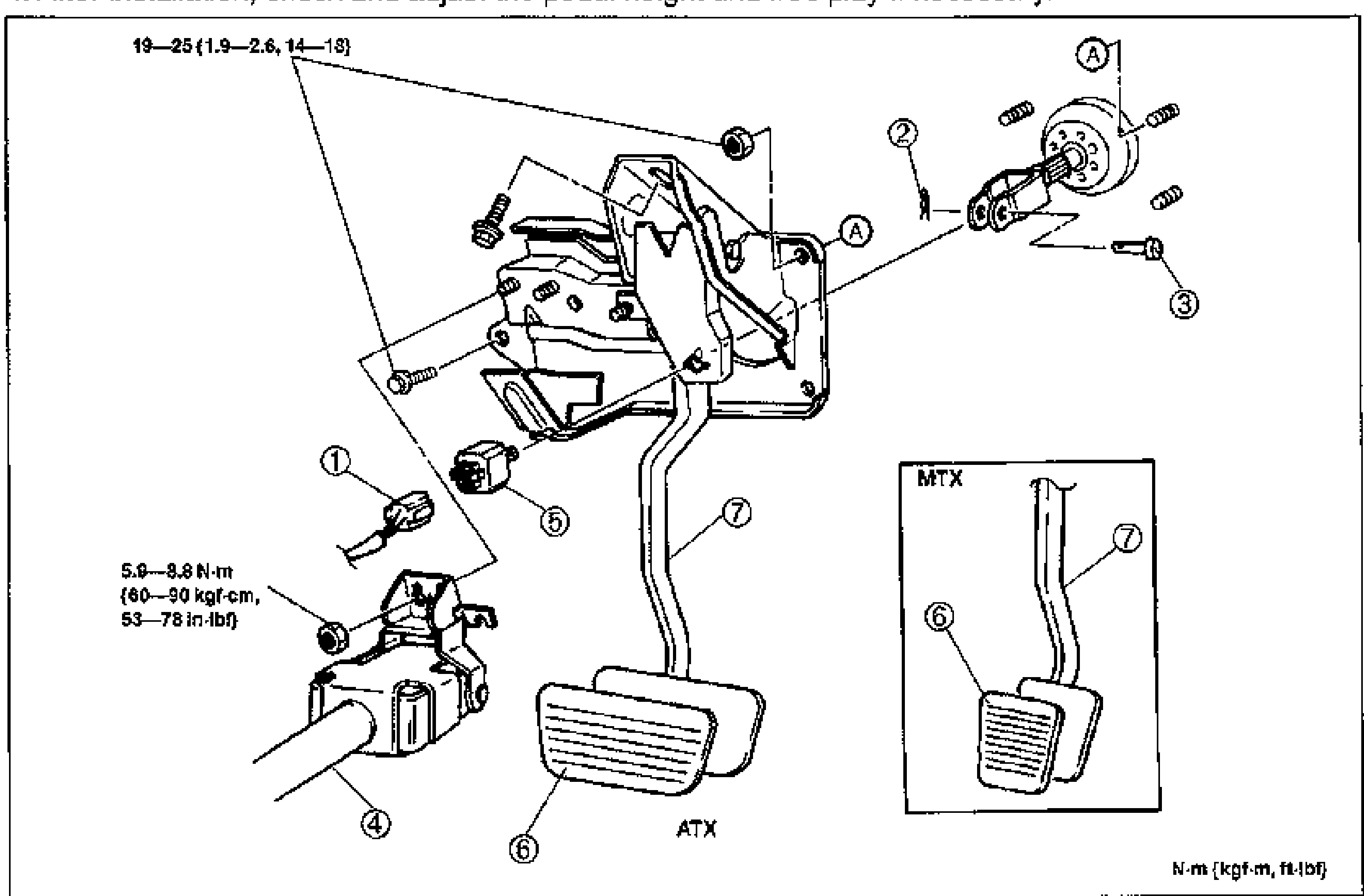
    Exploded view of the brake pedal assembly. Shows the brake pedal, brake switch and connector, snap pin, clevis pin, steering shaft, and pad. Numbered balloon callouts 1-7 with tightening torques. An MTX inset (top-right box) shows the manual-transmission pedal pad variant vs the ATX (automatic) layout. Torque units: N·m (kgf·m, ft-lbf).
  2. 2
    Inspect all parts and repair or replace as necessary.
  3. 3
    Install in the reverse order of removal.
  4. 4
    After installation, check and adjust the pedal height and free play if necessary.
Parts DiagramFig. fig1
#Part NameNotes
1Brake switch connector
2Snap pin
3Clevis pin
4Steering shaftService: section N; 5.9-8.8 N·m (60-90 kgf-cm, 53-78 in-lbf)
5Brake switchInspection: below; 19-25 N·m (1.9-2.6, 14-18)
6PadInspect for wear
7Brake pedalInspect for bending and damage

Inspection

Brake switch

Brake switch Inspection

  1. 1
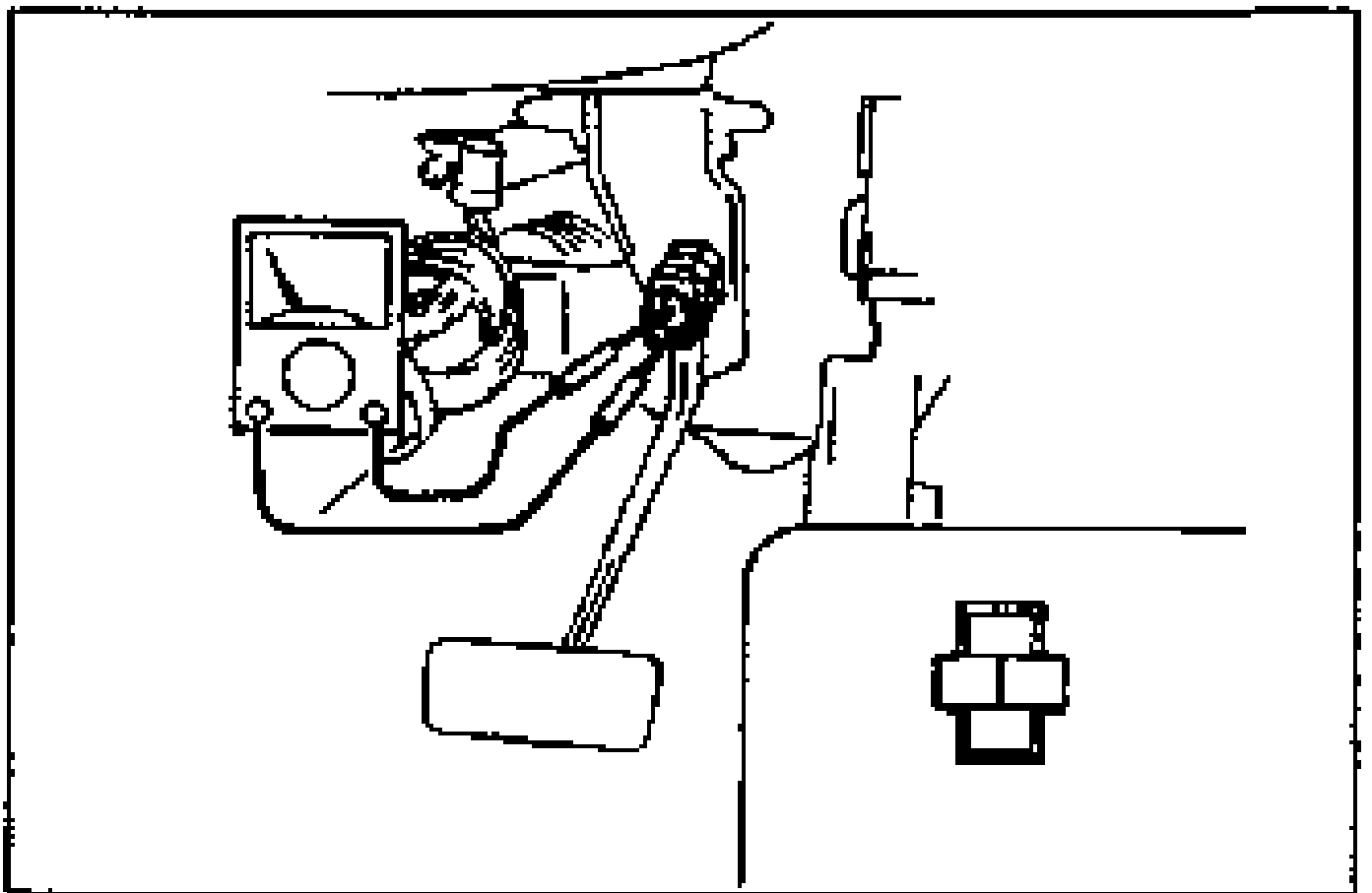
    Disconnect the brake switch connector.
    Brake switch inspection diagram showing an ohmmeter connected between the terminals of the brake switch mounted at the pedal bracket.
  2. 2
    Connect an ohmmeter between the terminals of the brake switch.
  3. 3
    Confirm continuity between the terminals when the brake pedal is depressed.

See also

Search Manual

Search pages, specs, and procedures