Mazda MX-3 silhouetteMX-3

Conventional Brake System — Removal / Installation (Caliper)

P-33parts diagram

Removal / Installation

Caliper

Caliper Removal / Installation

  1. 1
    Remove in the order shown in the figure.
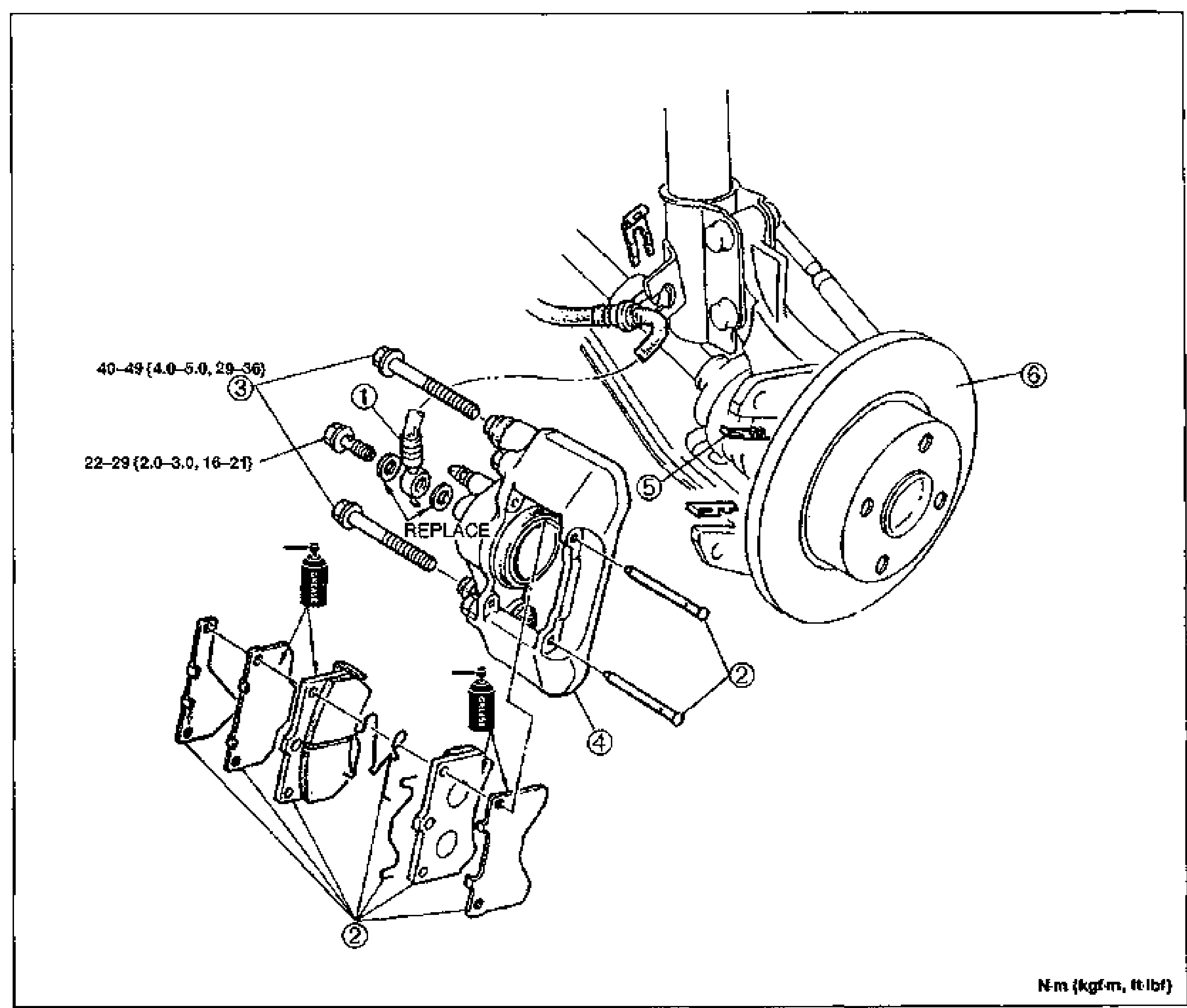
    Exploded view of the rear disc brake caliper assembly mounted to the knuckle/hub. Shows numbered balloon callouts 1-6 for the flexible hose, disc pad assembly, mounting bolts, caliper body (marked REPLACE), guide plate and disc plate (rotor). Tightening torque labels point to the upper bolt (40-49 N·m {4.0-5.0, 29-36}) and lower bolt (22-29 N·m {2.0-3.0, 16-21}). Unit note bottom-right: N·m (kgf·m, ft-lbf).
  2. 2
    Install in the reverse order of removal.
  3. 3
    Take the following steps after installation: Add fluid and bleed the air. (Refer to page P-7.) Check for fluid leakage. (Refer to page P-9.) Depress the brake pedal a few times and check that the rear brakes do not drag while rotating the wheel.
Parts DiagramFig. fig1
#Part NameNotes
1Flexible hose
2Disc pad assemblyInspection ... page P-34
3Bolt
4CaliperDisassembly / Inspection / Assembly ... page P-35
5Guide plate
6Disc plateInspection ... page P-34

Search Manual

Search pages, specs, and procedures