Mazda MX-3 silhouetteMX-3

FUEL SYSTEM

F2-112parts diagram

Disassembly / Assembly

Fuel Pump Disassembly / Assembly

  1. 1
    Remove the rear seat cushion.
  2. 2
    Disassemble in the order shown in the figure.
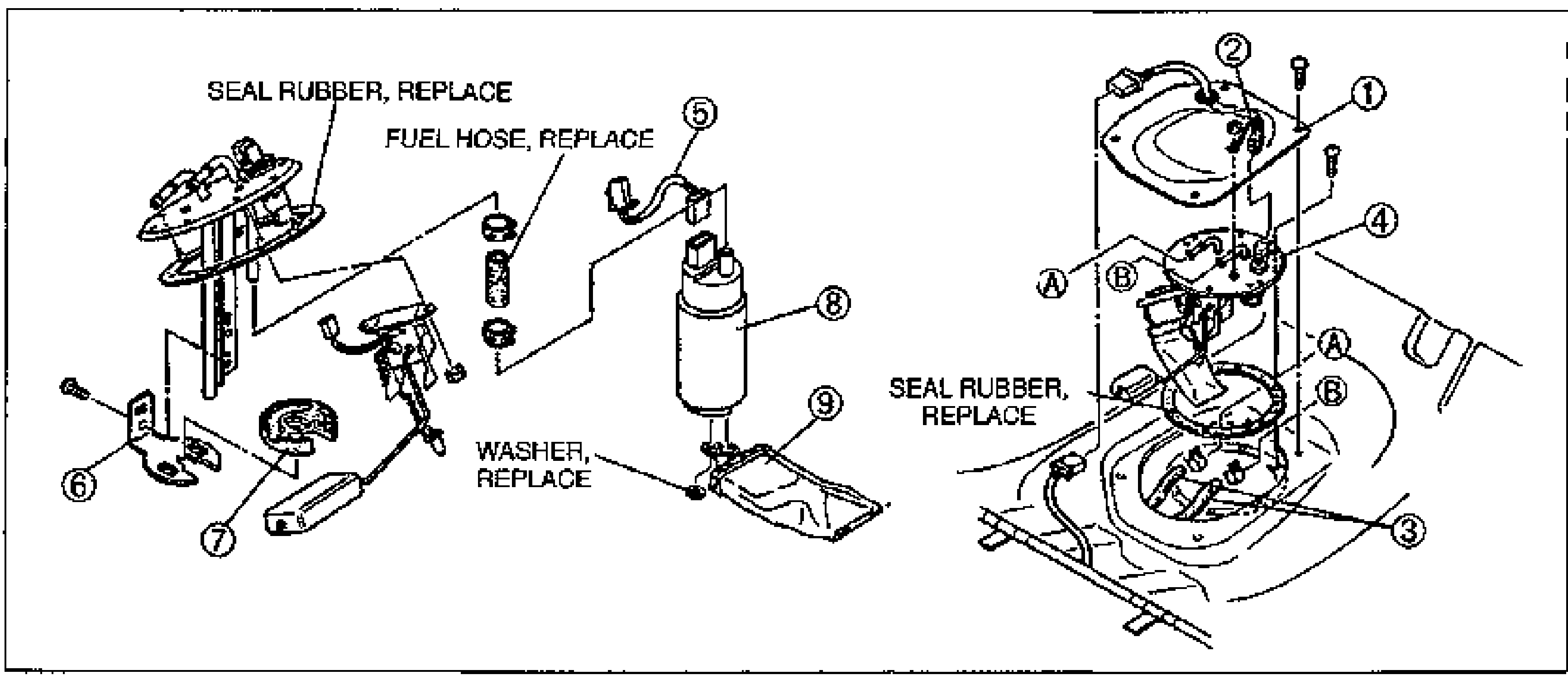
    Fuel pump disassembly exploded view. Left side shows the fuel pump cover assembly with balloons 6 (bracket) and 7 (rubber mount), with callouts SEAL RUBBER, REPLACE and FUEL HOSE, REPLACE. Center shows the fuel pump (8), fuel pump connector (5) and fuel filter low-pressure side (9) with a WASHER, REPLACE callout. Right shows the fuel pump cover (1), fuel gauge sender unit connector (2), fuel hose (3) and fuel gauge (4) with another SEAL RUBBER, REPLACE callout and circled A/B reference markers.
  3. 3
    Assemble in the reverse order of disassembly, referring to Assembly Note.
Parts DiagramFig. fig1
#Part NameNotes
1Fuel pump cover
2Fuel gauge sender unit connector
3Fuel hose
4Fuel gauge
5Fuel pump connector
6Bracket
7Rubber mount
8Fuel pump
9Fuel filter (Low pressure side)

Assembly Note

  1. 1
    Do not apply excessive side force when pushing the fuel hose onto the fuel pump nipple.
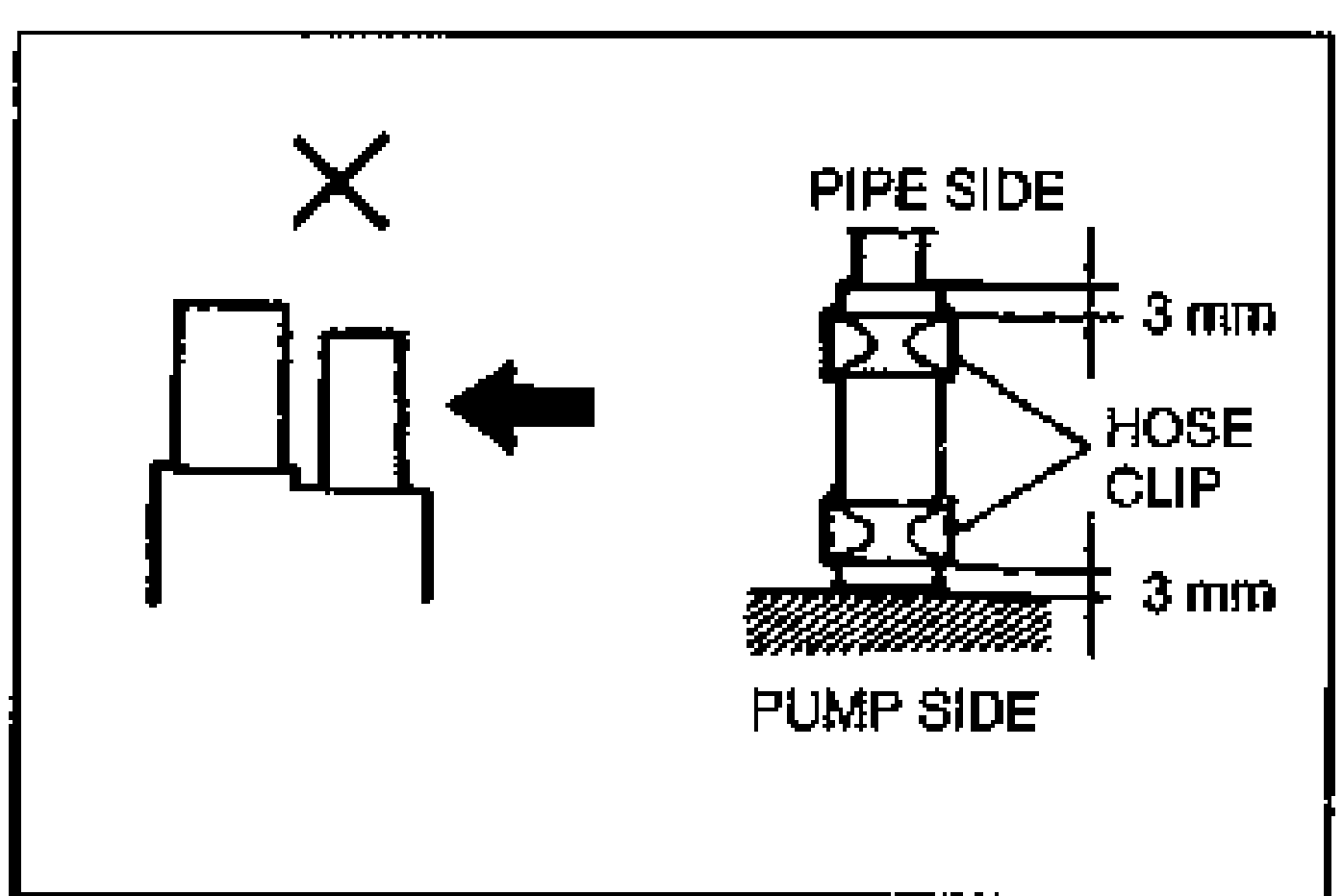
    Assembly Note detail. Left: an X (do-not) showing misaligned hose ends. Right: correct hose clip orientation with a HOSE CLIP positioned 3 mm from the PIPE SIDE and 3 mm from the PUMP SIDE, with an arrow indicating push direction.
  2. 2
    Install the clamps as shown.

FUEL PUMP

Fuel Pump Assembly Note

  1. 1
    After installing the fuel pump to the bracket, pull the pump down so that it is tight against the bracket.
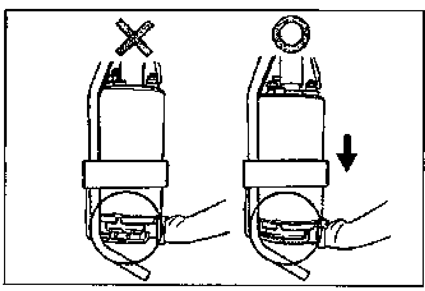
    Fuel pump assembly detail. Left: an X (do-not) showing the pump not seated against the bracket. Right: correct condition with an arrow showing the pump pulled down tight against the bracket.

See also

page F-106

Search Manual

Search pages, specs, and procedures