
FUEL SYSTEM
F2-108parts diagramFUEL TANK
Removal / Inspection / Installation
WARNING
Fuel vapor is hazardous. It can very easily ignite, causing serious injury and damage. Always keep sparks and flames away from fuel.
Fuel line spills and leaks are dangerous. Fuel can ignite and cause serious injuries or death and damage. Fuel can also irritate skin and eyes. To prevent this, always complete the "Fuel Line Safety Procedures" on page F2-106.
Repairing a fuel tank that has not been properly steam cleaned can be dangerous. Explosion or fire may cause death or serious injury. Always properly steam clean a fuel tank before repairing it.
Fuel Tank Removal / Inspection / Installation
- 1Remove in the order shown in the figure.
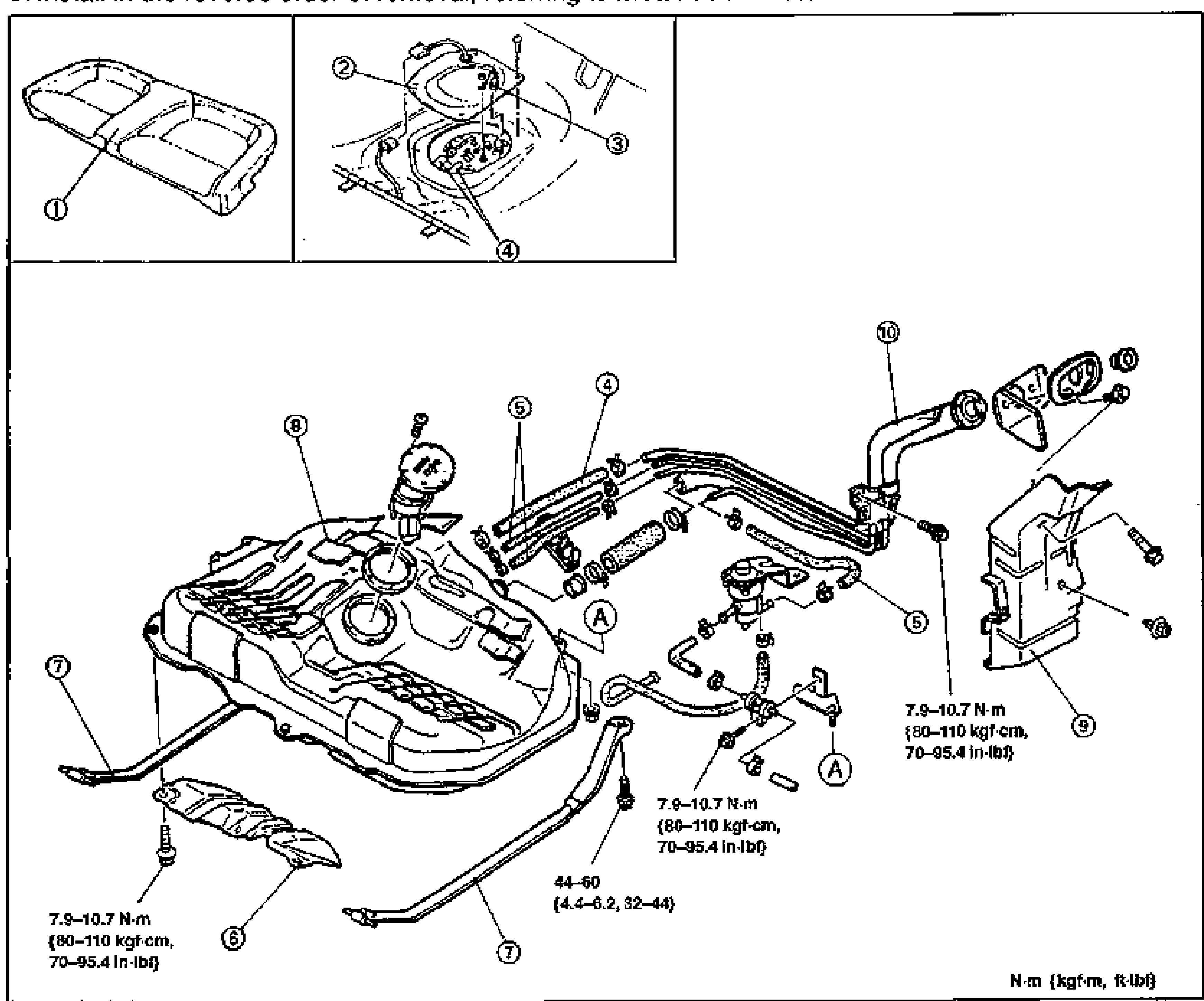
- 2Inspect the fuel tank components visually and repair or replace if necessary.
- 3Install in the reverse order of removal, referring to Installation Note.
Parts DiagramFig. fig1