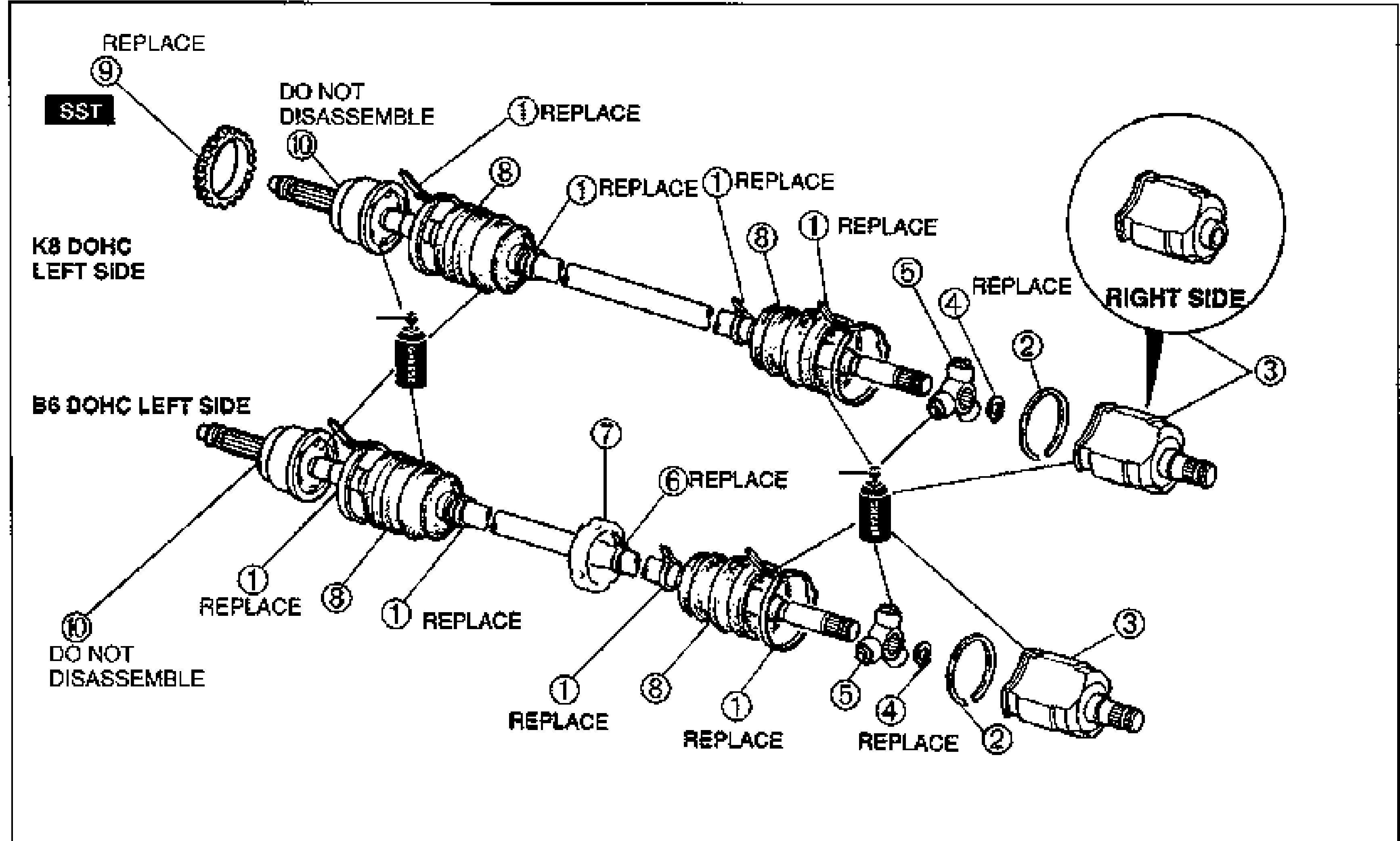
| 1 | Boot band | Disassembly Note: page M-30; Assembly Note: page M-32. REPLACE |
| 2 | Stopper ring | |
| 3 | Outer ring | Disassembly Note: page M-30. Inspect inside bore for wear, corrosion, and scoring. Assembly Note: page M-32. |
| 4 | Snap ring | Disassembly Note: page M-30; Assembly Note: page M-31. REPLACE |
| 5 | Tripod joint | Disassembly Note: page M-30. Inspect for damage and wear. Assembly Note: page M-31. |
| 6 | Band | Disassembly Note: page M-30; Assembly Note: page M-32. REPLACE |
| 7 | Dynamic damper | Disassembly Note: page M-30; Assembly Note: page M-31. |
| 8 | Boot | Disassembly Note: page M-30. Inspect for damage. Assembly Note: page M-31. |
| 9 | ABS sensor rotor | Disassembly Note: page M-31; Assembly Note: page M-31. SST. |
| 10 | Shaft and ball joint assembly | Inspect splines for damage and wear. Inspect wheel-side joint for excessive play and rough rotation. DO NOT DISASSEMBLE. |