
ANTI-LOCK BRAKE SYSTEM
P-70parts diagramRemoval / Installation
- 1Remove the nuts mounting the fuel filter and igniter to the bracket, and move them toward the engine.
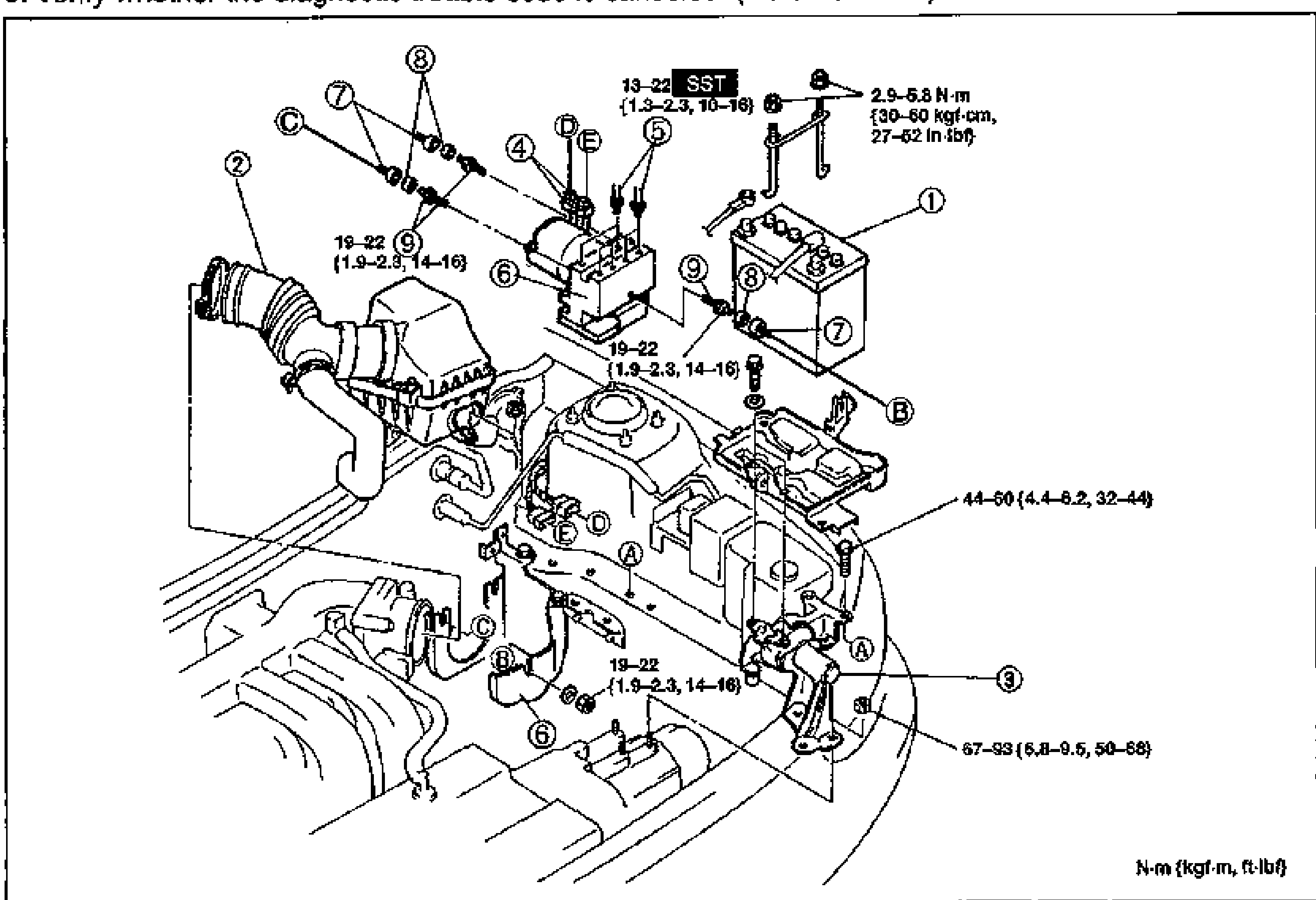
- 2Remove the hydraulic unit in order shown in the figure, referring to Removal Note.
- 3Install in the reverse order of removal, referring to Installation Note.
- 4Add brake fluid, bleed the air, and check for fluid leakage.
- 5Verify whether the diagnostic trouble code is canceled. (Refer to P-56.)
Parts DiagramFig. fig1
| Specification | Value |
|---|---|
| SST point | 13 - 22N·m |
| Connector screws | 2.9 - 5.8N·m |
| Mount/bracket bolts | 19 - 22N·m |
| Bracket bolt | 44 - 60N·m |
| Hex stud | 67 - 93N·m |
SST point
13 - 22N·m
Connector screws
2.9 - 5.8N·m
Mount/bracket bolts
19 - 22N·m
Bracket bolt
44 - 60N·m
Hex stud
67 - 93N·m
Removal Note - Brake pipes
CAUTION
Brake fluid will damage painted surfaces. If it does get on a painted surface, wipe it off immediately.
Loosen the brake pipes by using the SST.