Mazda MX-3 silhouetteMX-3

REAR AXLE — Removal / Inspection / Installation

M-12parts diagram

Removal / Inspection / Installation

  1. 1
    Remove in the order shown in the figure, referring to Removal Note.
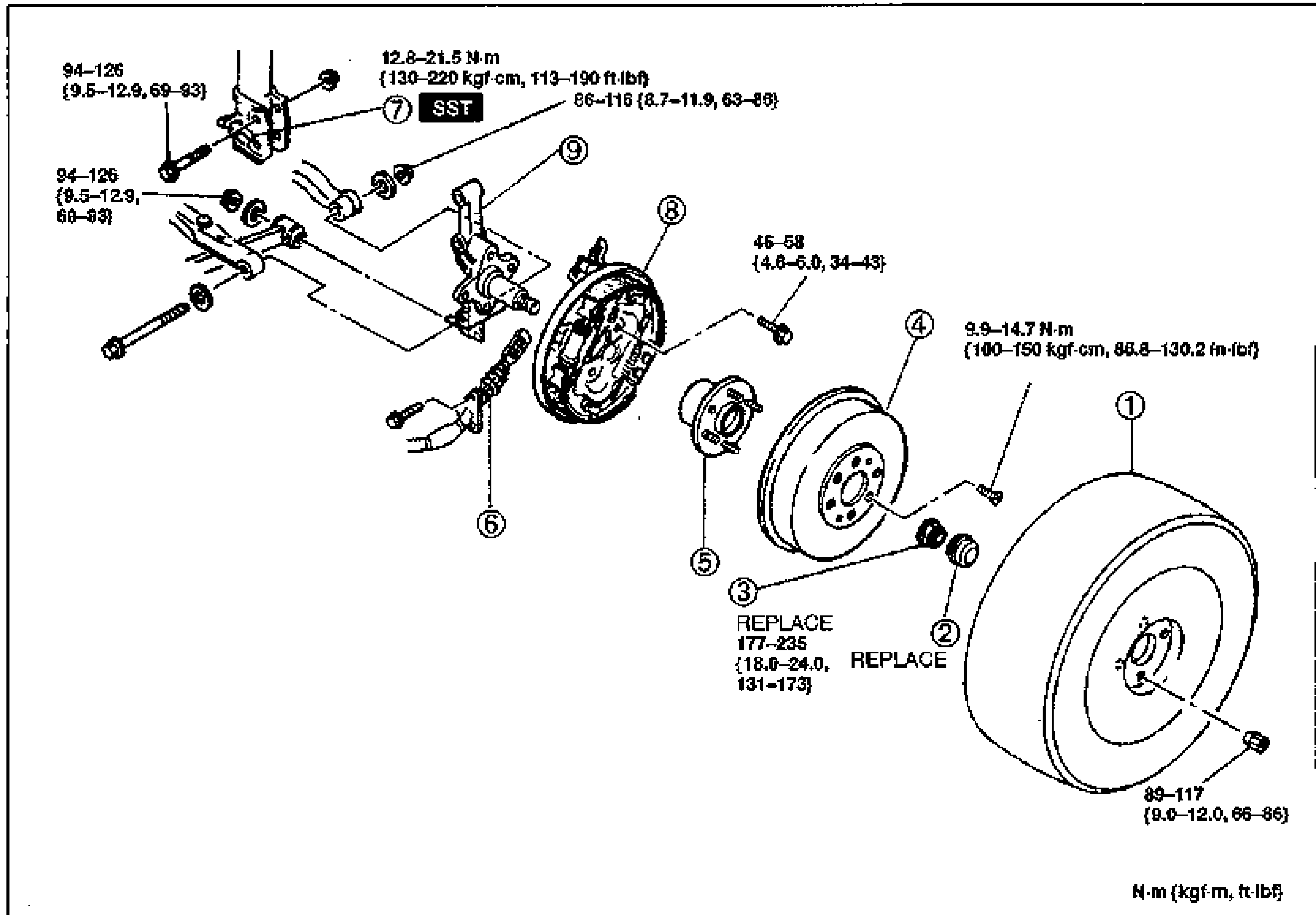
    Exploded view of the rear axle / drum brake assembly with torque values (N·m {kgf·m, ft·lbf}). Numbered balloons: 1 Wheel and tire, 2 Hub cap (REPLACE), 3 Locknut (REPLACE), 4 Brake drum, 5 Hub bearing assembly, 6 Parking brake cable, 7 Brake pipe (SST), 8 Rear brake assembly, 9 Rear hub spindle. Torque callouts: 94-126 N·cm {9.5-12.9, 69-93} for the spindle/backing bolts, 12.8-21.5 N·m {130-220 kgf·cm, 113-190 in·lbf} and 86-116 {8.7-11.9, 63-86} near the brake pipe, 45-58 {4.6-6.0, 34-43} on the brake-assembly bolt, 9.9-14.7 N·m {100-150 kgf·cm, 86.8-130.2 in·lbf} on the drum screw, 177-235 {18.0-24.0, 131-173} on the locknut, 89-117 {9.0-12.0, 66-86} on the wheel/tire.
  2. 2
    Inspect all parts and repair or replace as necessary.
  3. 3
    Install in the reverse order of removal, referring to Installation Note.
  4. 4
    After installation, bleed the brake system, adjust the parking brake lever stroke (Refer to Section P.) and check the rear wheel alignment. (Refer to Section R.)
Parts DiagramFig. fig1
#Part NameNotes
1Wheel and tireTightening torque 89-117 N·m {9.0-12.0 kgf·m, 66-86 ft·lbf}
2Hub capREPLACE
3LocknutREPLACE. Tightening torque 177-235 N·m {18.0-24.0 kgf·m, 131-173 ft·lbf}. Removal Note below; Installation Note page M-13
4Brake drumDrum screw torque 9.9-14.7 N·m {100-150 kgf·cm, 86.8-130.2 in·lbf}
5Hub bearing assemblyInspect for cracks and damage. Disassembly / Assembly page M-13
6Parking brake cableService Section P
7Brake pipeSST. Removal Note page M-13; Installation Note page M-13
8Rear brake assemblyService Section P
9Rear hub spindleInspect for cracks and damage
Spindle / backing plate bolts
94-126 N·cm {9.5-12.9 kgf·m, 69-93 ft·lbf}
Brake pipe flare nut
12.8 - 21.5N·m
Brake pipe bracket
86 - 116N·m
Rear brake assembly bolt
45 - 58N·m
Brake drum screw
9.9 - 14.7N·m

Removal Note

Locknut

  1. 1
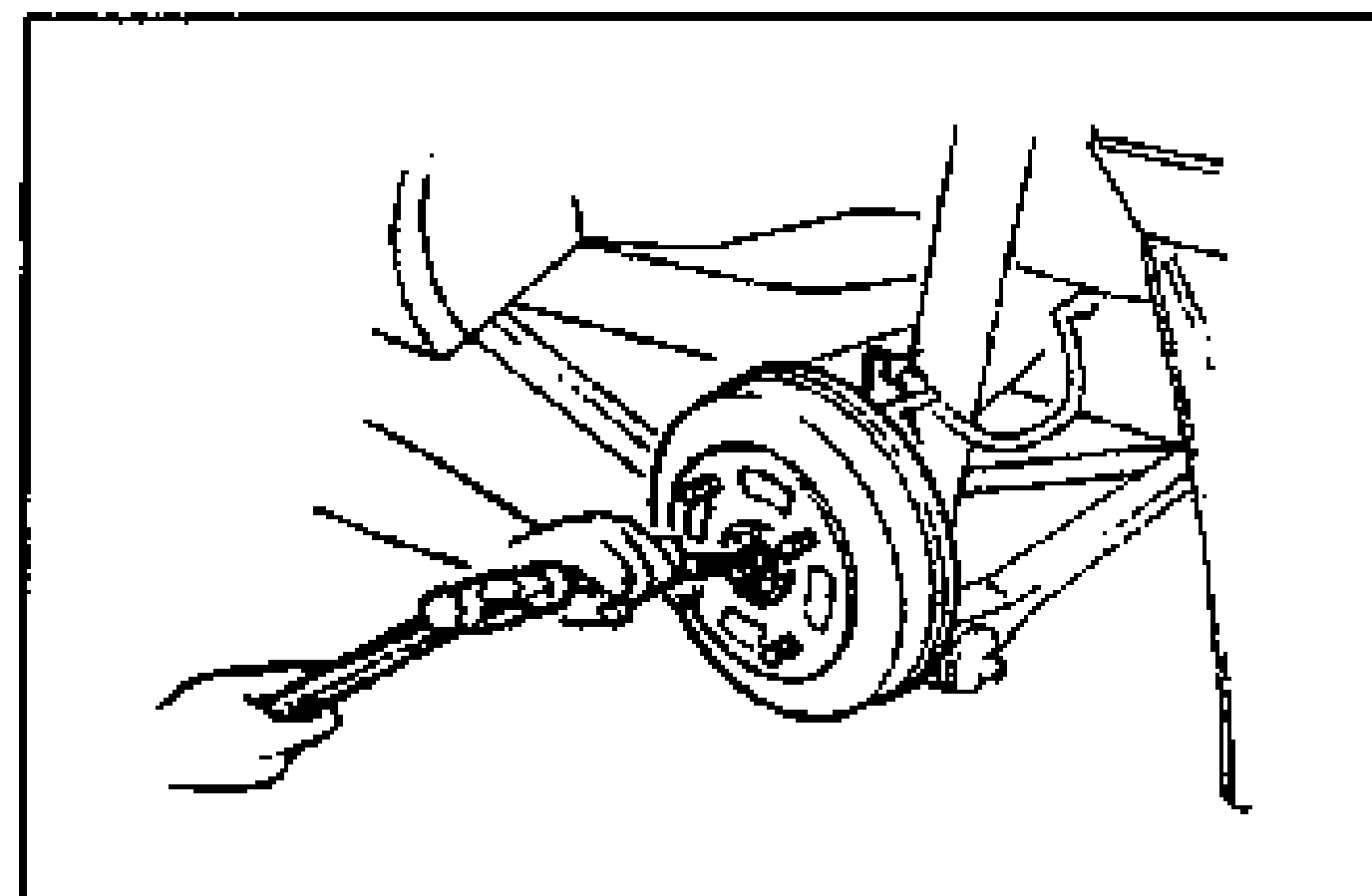
    Raise the staked portion of the locknut using a small cape chisel.
  2. 2
    Lock the hub by applying the brakes.
    Rear drum-brake hub on the trailing arm with the parking brake cable attached, illustrating the locknut removal note (locking the hub by applying the brakes).
  3. 3
    Remove the locknut.

Search Manual

Search pages, specs, and procedures