
CONVENTIONAL BRAKE SYSTEM - MASTER CYLINDER (B6 DOHC)
P-12parts diagramB6 DOHC engine, NON ABS master cylinder. Hose item 3 applies to MTX (manual transmission).
MASTER CYLINDER (B6 DOHC)
Removal / Installation / Inspection (NON ABS)
- 1Remove in the order shown in the figure, referring to Removal Note.
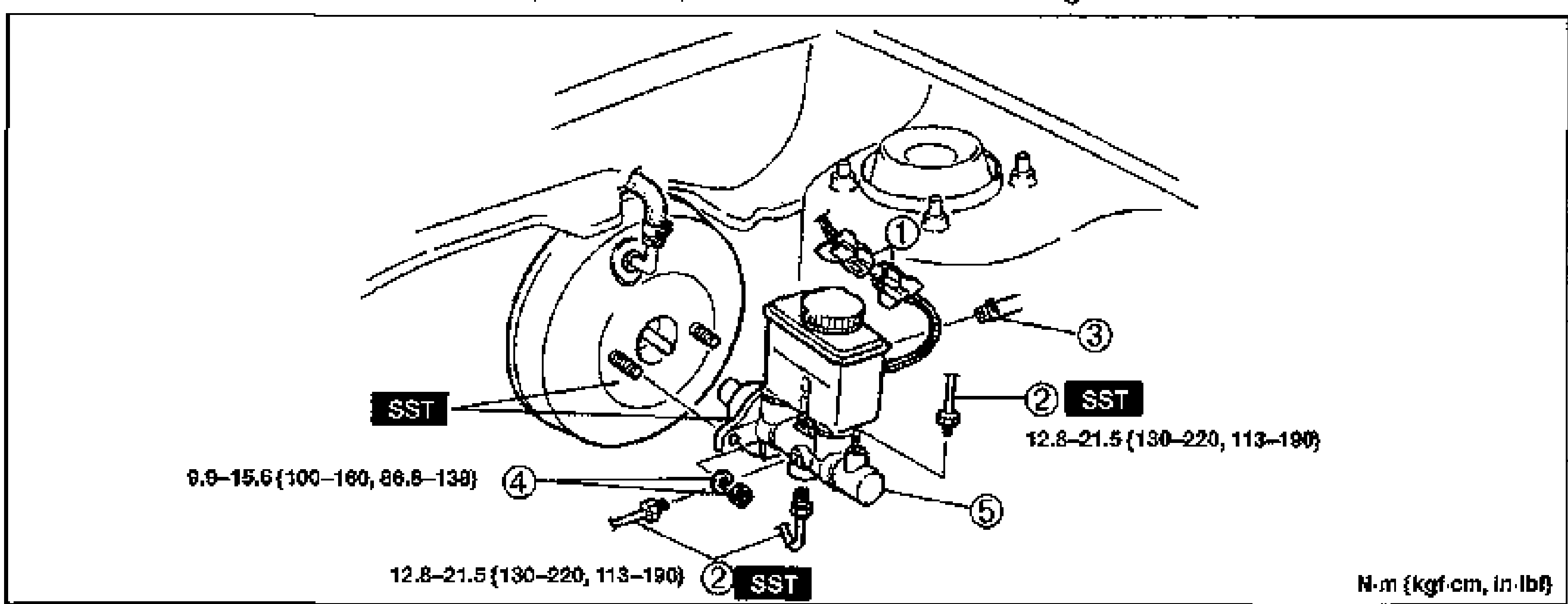
- 2Install in the reverse order of removal, referring to Installation Note.
- 3After installation, add brake fluid, bleed air, and check for fluid leakage.
Parts DiagramFig. fig1
Removal Note
Brake pipe
Disconnect the brake pipe from the master cylinder by using the SST.
CAUTION
Brake fluid will damage painted surfaces. If brake fluid does get on a painted surface, wipe it off immediately.
Installation Note
Master cylinder - Piston to push rod clearance
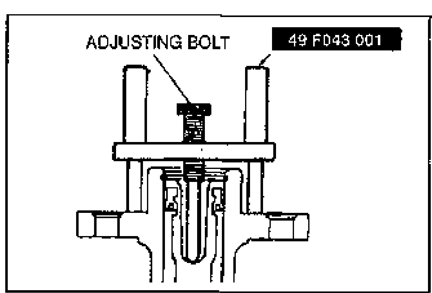
Before installing the master cylinder, check the clearance between the piston of the master cylinder and the push rod of the power brake unit as follows.
Piston to push rod clearance
- 1Place the SST atop the master cylinder. Turn the adjusting bolt until it bottoms in the push rod hole in the piston.
 49 F043 001