Mazda MX-3 silhouetteMX-3

Steering Wheel and Column — Removal/Installation

N-13parts diagram

Item 1 differs by horn cap vs air bag module — figure notes 'VEHICLES WITHOUT AIR BAG'. Item 10 interlock cable is ATX (automatic transaxle) only.

Removal/Installation

  1. 1
    Remove in the order shown in the figure, referring to Removal Note.
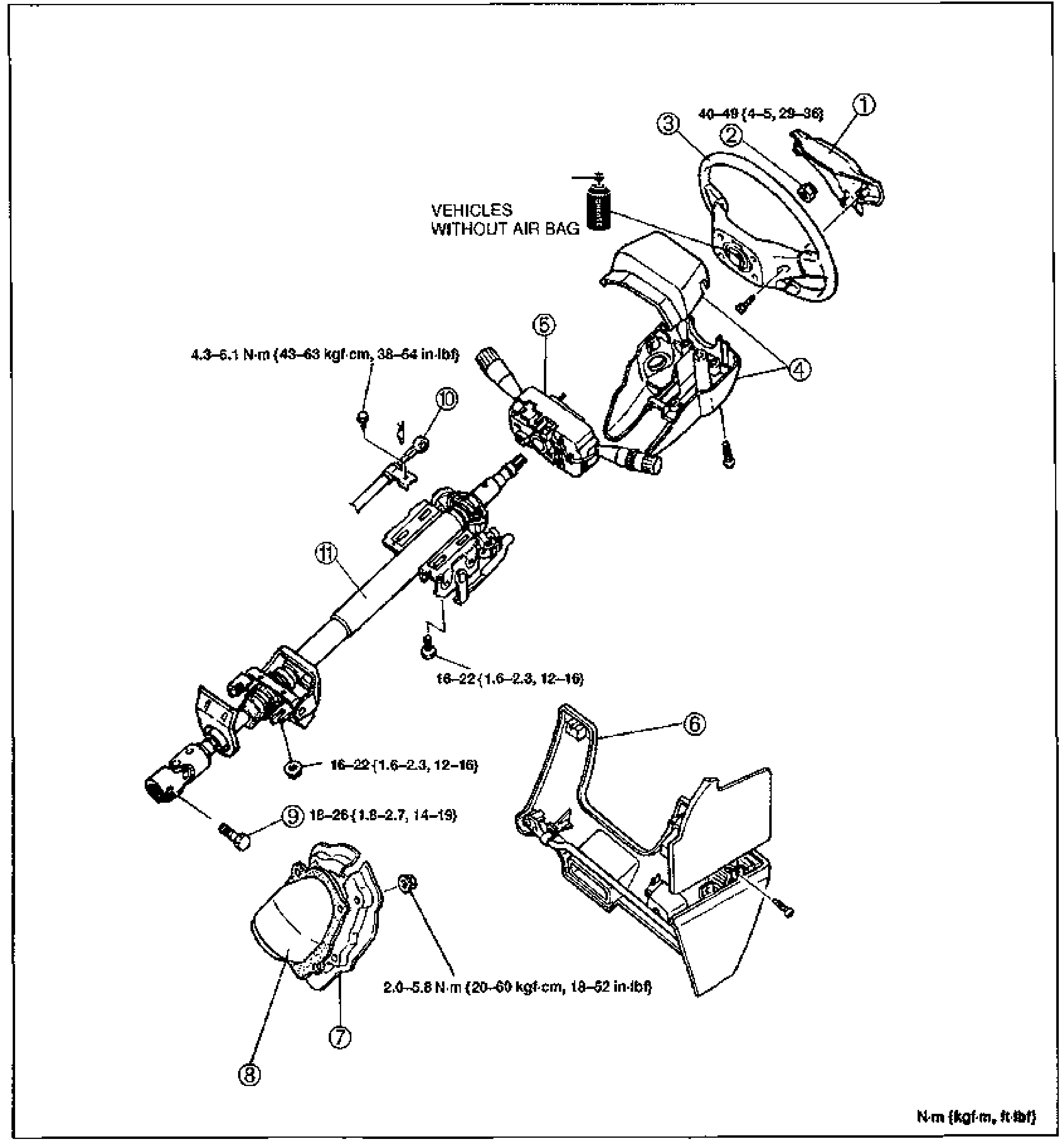
    Exploded view of the steering wheel and steering column assembly. From upper right: horn cap / air bag module (1), locknut (2), steering wheel (3), column cover (4), combination switch (5), lower panel (6), set plate (7), dust cover (8), fixing bolt (9), interlock cable (10, ATX only), and steering shaft assembly (11). Tightening-torque callouts shown: 40—49 {4—5, 29—36} at the steering wheel locknut, 4.3—6.1 N·m {43—63 kgf·cm, 38—54 in·lbf}, 16—22 {1.6—2.3, 12—16} (two locations), 18—26 {1.8—2.7, 14—19}, and 2.0—5.8 N·m {20—60 kgf·cm, 18—52 in·lbf}. A note marks 'VEHICLES WITHOUT AIR BAG' for the horn cap area.
  2. 2
    Install in the reverse order of removal, referring to Installation Note.
Parts DiagramFig. fig1
#Part NameNotes
1Horn cap or air bag moduleService: Body electrical troubleshooting manual, section S
2Locknut
3Steering wheelRemoval Note: page N-14; Installation Note: page N-14
4Column cover
5Combination switchOperation: section T
6Lower panel
7Set plate
8Dust cover
9Fixing bolt (intermediate shaft / pinion shaft)Installation Note: page N-21
10Interlock cable (ATX only)
11Steering shaft assemblyDisassembly / Inspection / Assembly: page N-14
Tightening torque (steering wheel locknut)
392 - 481N·m
42 - 60N·m
two locations
157 - 216N·m
20 - 57N·m

Search Manual

Search pages, specs, and procedures