Mazda MX-3 silhouetteMX-3

ENGINE SPEED SENSING POWER STEERING — Steering Gear and Linkage (B6 DOHC) Removal / Installation

N-19parts diagram

Procedure is for the B6 DOHC engine. Callout 8 (extension bar / control rod) is MTX (manual transaxle) only.

STEERING GEAR AND LINKAGE (B6 DOHC)

Removal / Installation

  1. 1
    Loosen the wheel lug nuts.
  2. 2
    Jack up the front of the vehicle and support it with safety stands.
  3. 3
    Remove the wheels.
  4. 4
    Remove in the order shown in the figure, referring to Removal Note.
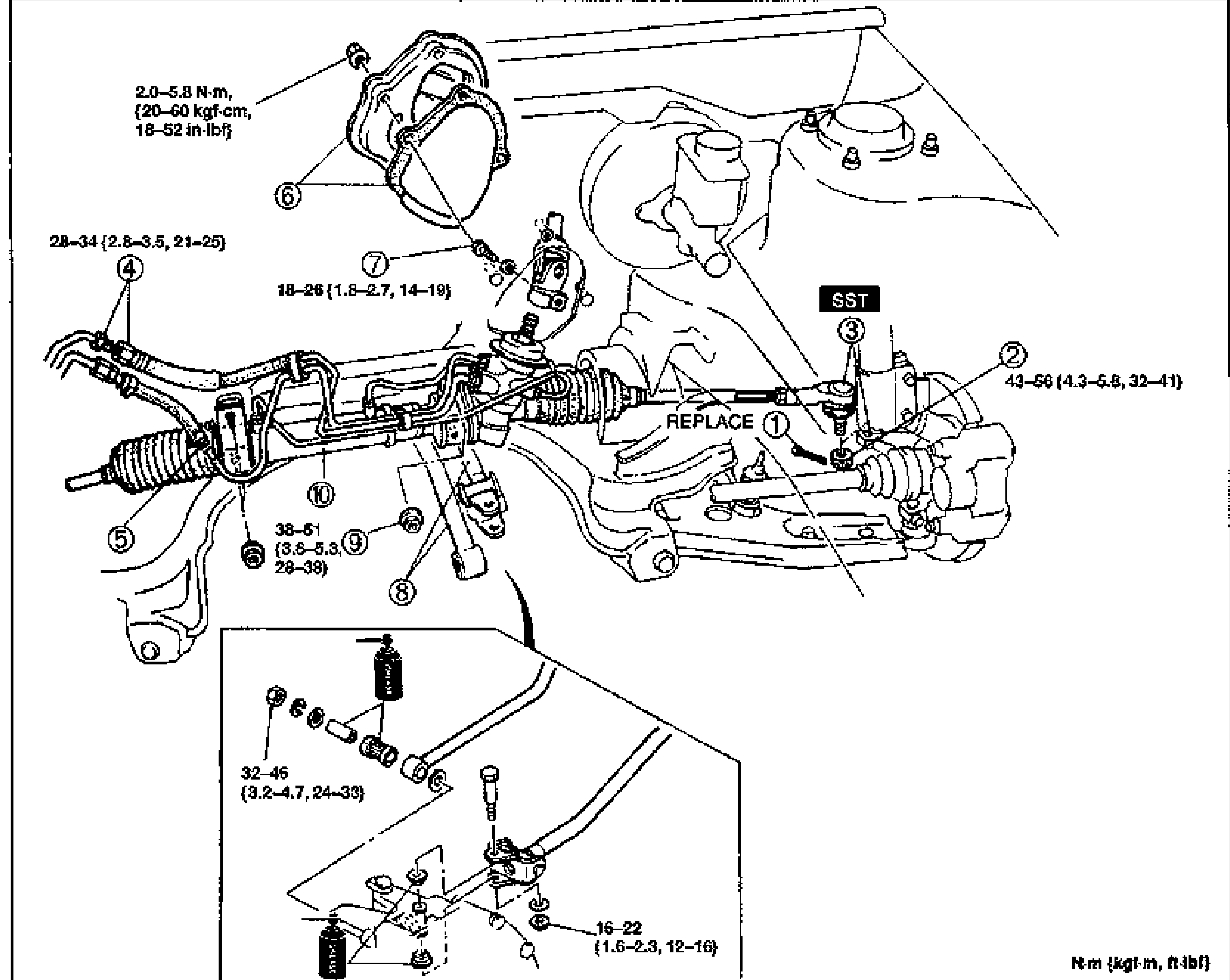
    Exploded view of the steering gear and linkage for the B6 DOHC engine, showing the rack-and-pinion gear, pressure pipe, return hose, set plate and dust cover, tie-rod ends, intermediate/pinion shaft and crossmember mounting. Numbered balloon callouts 1-10 with several tightening torque annotations. An inset (lower left) detail shows the intermediate shaft / pinion shaft fixing area with additional fasteners. 'SST' tool box appears near callout 3, and 'REPLACE' labels the cotter pin (1). Units note: N·m {kgf·m, ft-lbf}.
  5. 5
    Install in the reverse order of removal, referring to Installation Note.
  6. 6
    After installation, bleed air from the steering system and adjust the toe-in if necessary. (Refer to section R.)
Parts DiagramFig. fig1
#Part NameNotes
1Cotter pinREPLACE
2Locknut
3Tie-rod end ball jointRemoval Note: page N-17; SST
4Pressure pipe
5Return hose
6Set plate and dust cover
7Fixing bolt (intermediate shaft / pinion shaft)Installation Note: page N-21
8Extension bar / Control rod (MTX)MTX only
9Nut (steering gear mounting bolt)Installation Note: page N-21
10Steering gear and linkageRemoval Note: page N-21

Search Manual

Search pages, specs, and procedures