Mazda MX-3 silhouetteMX-3

DRIVE SHAFT (TRIPOD JOINT)

M-25parts diagram

Engine mount member (item 8) is only for ATX at the left side drive shaft.

Removal / Installation

  1. 1
    Drain the transaxle oil before removal.
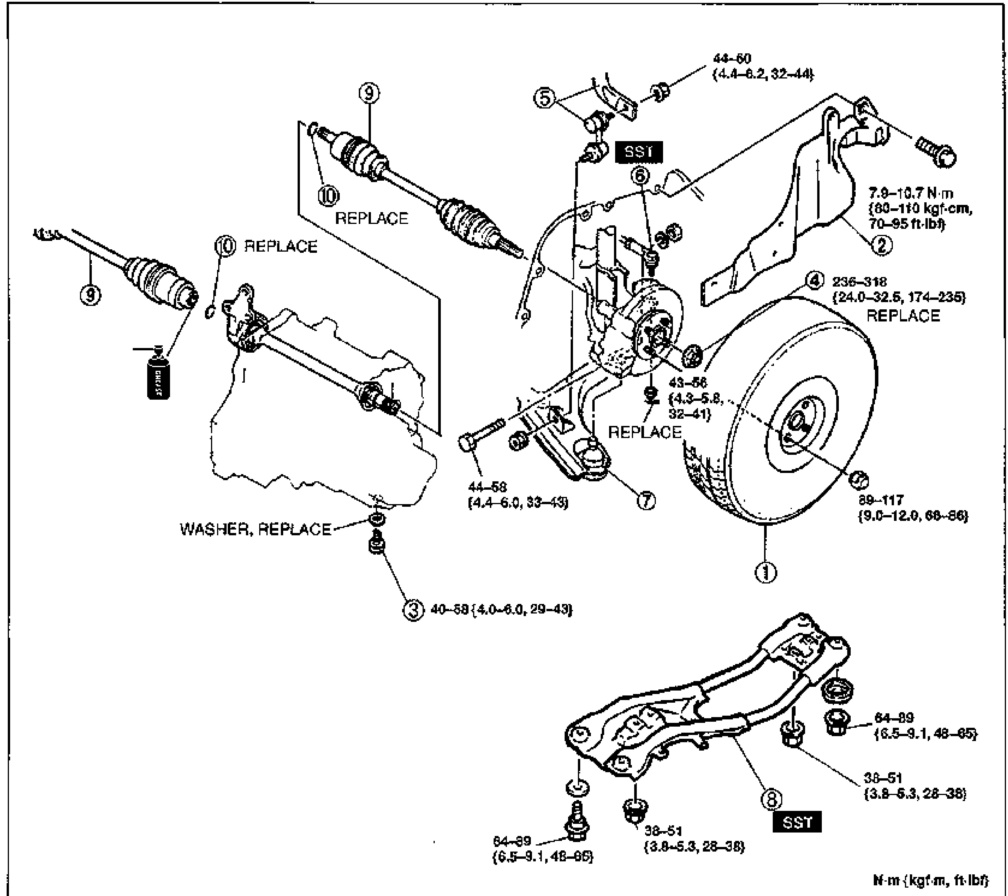
    Exploded view of the drive shaft (tripod joint) removal-installation with numbered balloon callouts 1-10 and tightening torque annotations. Shows wheel and tire (1), splash shield (2), drain plug (3) with WASHER REPLACE, locknut (4) REPLACE, stabilizer control link (5), tie-rod end (6) installed with SST, lower ball joint (7), engine mount member (8) with SST, drive shaft (9) REPLACE, and clip (10) REPLACE. Torque values are in N·m {kgf·m, ft·lbf}.
  2. 2
    Remove in the order shown in the figure, referring to Removal Note.
  3. 3
    Install in the reverse order of removal, referring to Installation Note.
  4. 4
    After installation, fill the transaxle with the specified amount of the specified transaxle oil and inspect for oil leakage.
  5. 5
    Check the front wheel alignment, referring to Section R.
Parts DiagramFig. fig1
#Part NameNotes
1Wheel and tire89-117 N·m {9.0-12.0 kgf·m, 66-86 ft·lbf}
2Splash shield7.9-10.7 N·m {80-110 kgf·cm, 70-95 ft·lbf}
3Drain plugWASHER, REPLACE; 40-58 N·m {4.0-6.0 kgf·m, 29-43 ft·lbf}
4LocknutREPLACE; 236-318 N·m {24.0-32.5 kgf·m, 174-235 ft·lbf}; Removal Note page M-26, Installation Note page M-28
5Stabilizer control link44-60 N·m {4.4-6.2 kgf·m, 32-44 ft·lbf}
6Tie-rod endInstalled with SST; 43-56 N·m {4.3-5.8 kgf·m, 32-41 ft·lbf}; Removal Note page M-26, Installation Note page M-28
7Lower ball joint44-58 N·m {4.4-6.0 kgf·m, 33-43 ft·lbf}
8Engine mount memberOnly for ATX at left side drive shaft; with SST; 64-89 N·m {6.5-9.1 kgf·m, 48-65 ft·lbf} and 38-51 N·m {3.8-5.3 kgf·m, 28-38 ft·lbf}; Removal Note page M-26
9Drive shaftREPLACE; Removal Note page M-26, Installation Note page M-27, Disassembly/Inspection/Assembly page M-29
10ClipREPLACE; Installation Note page M-27

Search Manual

Search pages, specs, and procedures