
CONVENTIONAL BRAKE SYSTEM
P-44parts diagramAfter installation
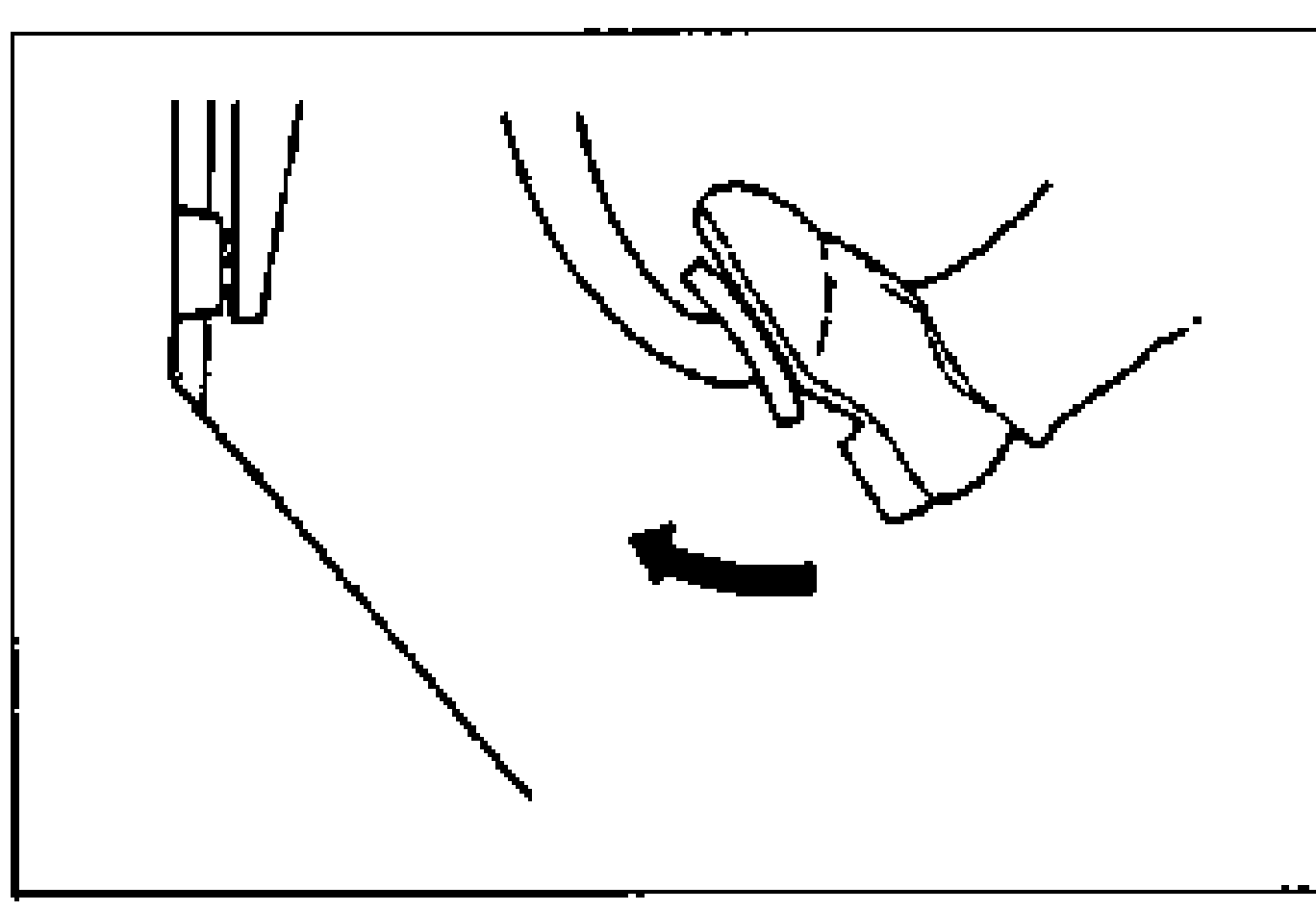
- 3Take the following steps after installation: - Add fluid and bleed the air. (Refer to page P-7.) - Check for fluid leakage. (Refer to page P-9.) - Depress the brake pedal a few times; then verify that the rear brakes do not drag while rotating the wheel. - Check the parking brake lever stroke. (Refer to page P-45.)
WHEEL CYLINDER
Disassembly / Inspection / Assembly
Wheel cylinder disassembly / inspection / assembly
- 1Disassemble the wheel cylinder in the order shown in the figure.
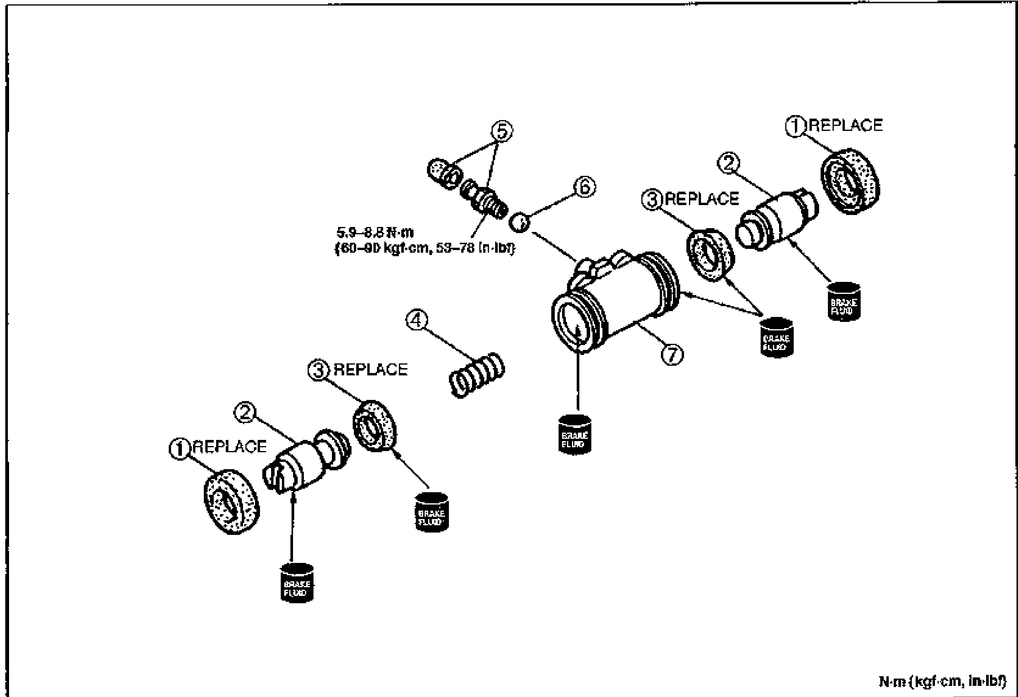
- 2Inspect all parts and repair or replace as necessary. If a problem is found in wheel cylinder body or piston replace the wheel cylinder as an assembly.
- 3Assemble in the reverse order of disassembly.
Parts DiagramFig. fig2
| Specification | Value |
|---|---|
| Bleeder screwwheel cylinder | 5.9 - 8.8N·m |
Bleeder screwwheel cylinder
5.9 - 8.8N·m