Mazda MX-3 silhouetteMX-3

CONVENTIONAL BRAKE SYSTEM

P-17parts diagram

Diagram shows two variants: B6 DOHC NON ABS (main) and B6 DOHC ABS (inset). Item 7 differs between variants (stop screw and O-ring for NON ABS; stop pin and O-ring for ABS); item 8 is snap ring for NON ABS and snap ring and space for ABS.

Disassembly / Assembly / Inspection

  1. 1
    After removing the brake fluid, disassemble in the order shown in the figure.
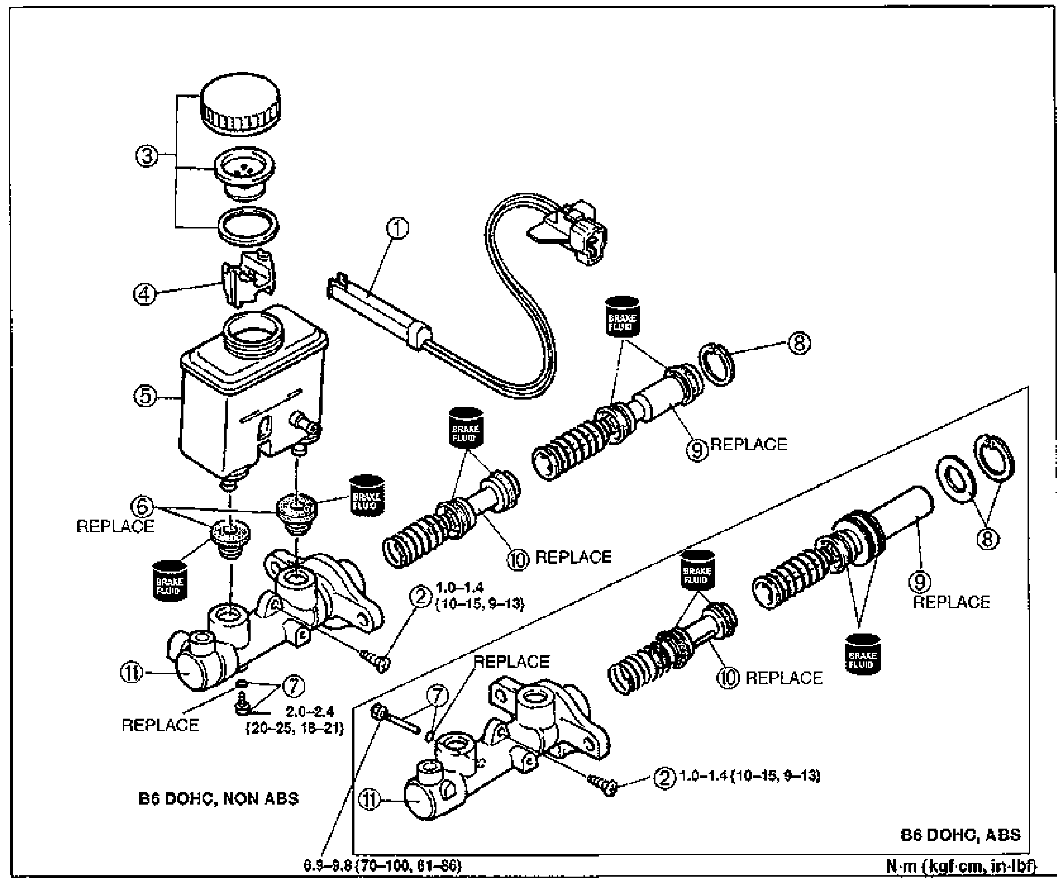
    Exploded view of the brake master cylinder disassembly. Main diagram is labeled B6 DOHC, NON ABS; an inset at the lower right is labeled B6 DOHC, ABS. Numbered balloon callouts: (1) fluid level sensor, (2) screw, (3) cap set, (4) float, (5) reservoir, (6) bushings (REPLACE), (7) stop screw and O-ring (NON ABS) / stop pin and O-ring (ABS), (8) snap ring, (9) primary piston assembly (REPLACE), (10) secondary piston assembly (REPLACE), (11) master cylinder body. BRAKE FLUID application points are marked on the pistons. Torque values: screw (2) 1.0–1.4 {10–15, 9–13}; stop screw (7) 2.0–2.4 {20–25, 18–21}; lower-left value 6.9–9.8 {70–100, 61–86}. Units N·m {kgf·cm, in·lbf}.
  2. 2
    Inspect all parts and repair or replace as necessary.
  3. 3
    Assemble in the reverse order of removal, referring to Assembly Note.
Parts DiagramFig. fig1
#Part NameNotes
1Fluid level sensorInspection ... page P-13
2ScrewTightening torque 1.0–1.4 N·m {10–15 kgf·cm, 9–13 in·lbf}
3Cap set
4Float
5ReservoirInspect for damage and deformation
6BushingsReplace
7Stop screw and O-ring (B6 DOHC, NON ABS) / Stop pin and O-ring (B6 DOHC, ABS)Assembly Note ... page P-18; tightening torque 2.0–2.4 N·m {20–25 kgf·cm, 18–21 in·lbf}
8Snap ring (B6 DOHC, NON ABS) / Snap ring and space (B6 DOHC, ABS)
9Primary piston assemblyInspect for abnormal wear, rust, and damage
10Secondary piston assemblyAssembly Note ... page P-18; inspect for abnormal wear, rust, and damage
11Master cylinder bodyInspect for abnormal wear, rust, and damage

Search Manual

Search pages, specs, and procedures