
Steering Wheel — Removal/Installation Notes; Steering Shaft Disassembly/Inspection/Assembly
N-14parts diagramLock bolts and universal-joint washer must be replaced (marked REPLACE in figure).
Removal Note
Steering wheel
CAUTION
Do not try to remove the steering wheel by hitting the shaft with a hammer. The column will collapse.
Remove the steering wheel with a suitable puller.
Installation Note
Steering wheel
With the wheels in the straight-ahead position, install the steering wheel.
Disassembly / Inspection / Assembly
- 1Disassemble in the order shown in the figure, referring to Disassembly Note.
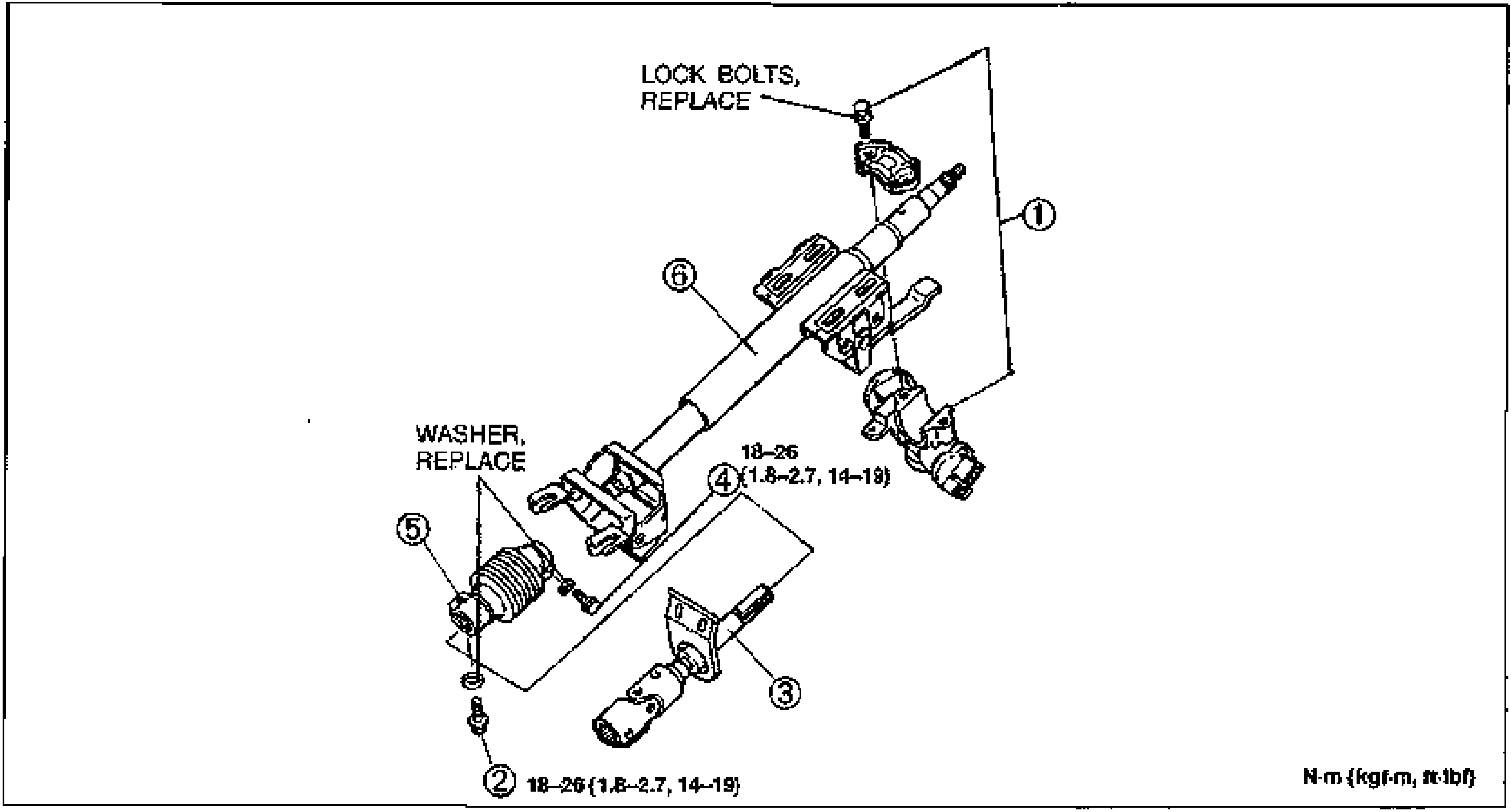
- 2Assemble in the reverse order of disassembly, referring to Assembly Note.
Parts DiagramFig. fig3
| Specification | Value |
|---|---|
| Tightening torque (fixing bolts, items 2 and 4) | ≈177 - 255N·m |
Tightening torque (fixing bolts, items 2 and 4)
177 - 255N·m