Mazda MX-3 silhouetteMX-3

FRONT AXLE — Disassembly / Inspection / Assembly

M-8parts diagram

Disassembly / Inspection / Assembly

  1. 1
    Disassemble in the order shown in the figure, referring to Disassembly Note.
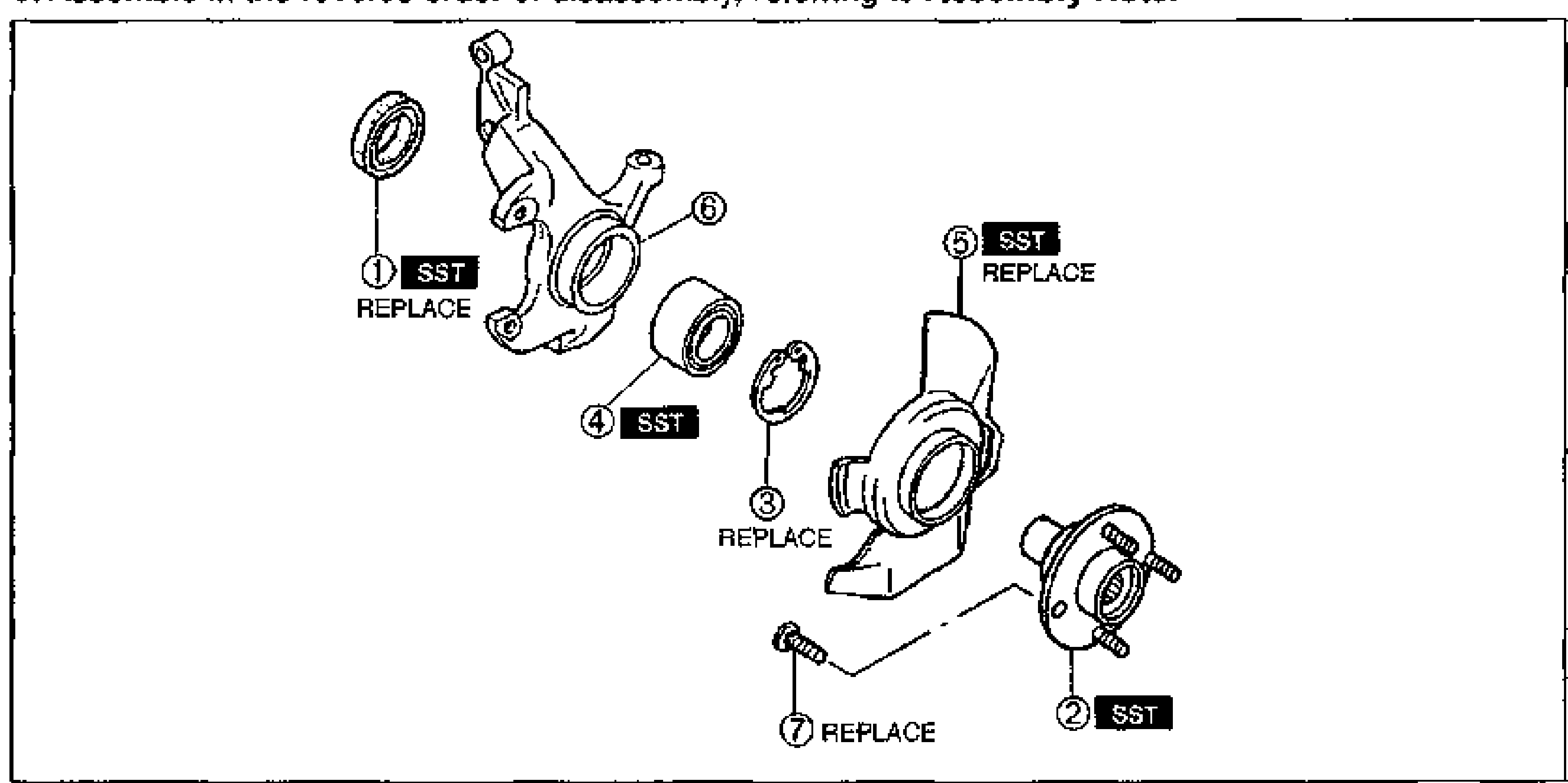
    Exploded view of the front axle / steering knuckle and front wheel hub assembly. Numbered balloons: 1 Oil seal (SST, REPLACE), 2 Front wheel hub assembly (SST), 3 Retaining ring (REPLACE), 4 Wheel bearing (SST), 5 Dust cover (SST, REPLACE), 6 Knuckle, 7 Hub bolt (REPLACE). The knuckle, bearing, retaining ring, dust cover, hub and hub bolt are shown separated along their assembly axis.
  2. 2
    Inspect all parts and repair or replace as necessary.
  3. 3
    Assemble in the reverse order of disassembly, referring to Assembly Note.
Parts DiagramFig. fig1
#Part NameNotes
1Oil sealSST; REPLACE. Assembly Note page M-10
2Front wheel hub assemblySST. Disassembly Note below; Assembly Note page M-10
3Retaining ringREPLACE
4Wheel bearingSST. Disassembly Note page M-9; Assembly Note page M-10
5Dust coverSST; REPLACE. Disassembly Note page M-9; Assembly Note page M-10
6Knuckle
7Hub boltREPLACE. Disassembly Note page M-9; Assembly Note page M-9

Disassembly Note

Front wheel hub assembly

  1. 1
    Remove the front wheel hub assembly by using the SSTs.
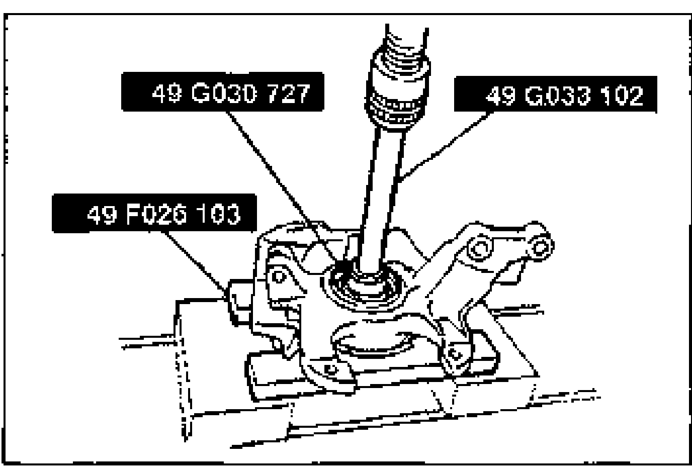
    SSTs set up on the knuckle to press out / remove the front wheel hub assembly. Three tool labels point to the rig: 49 G030 727, 49 G033 102, and 49 F026 103.
  2. 2
    If the bearing inner race remains on the front wheel hub assembly, grind a section of the bearing inner race until approx. 0.5 mm {0.020 in} remains. Then remove it with a chisel.
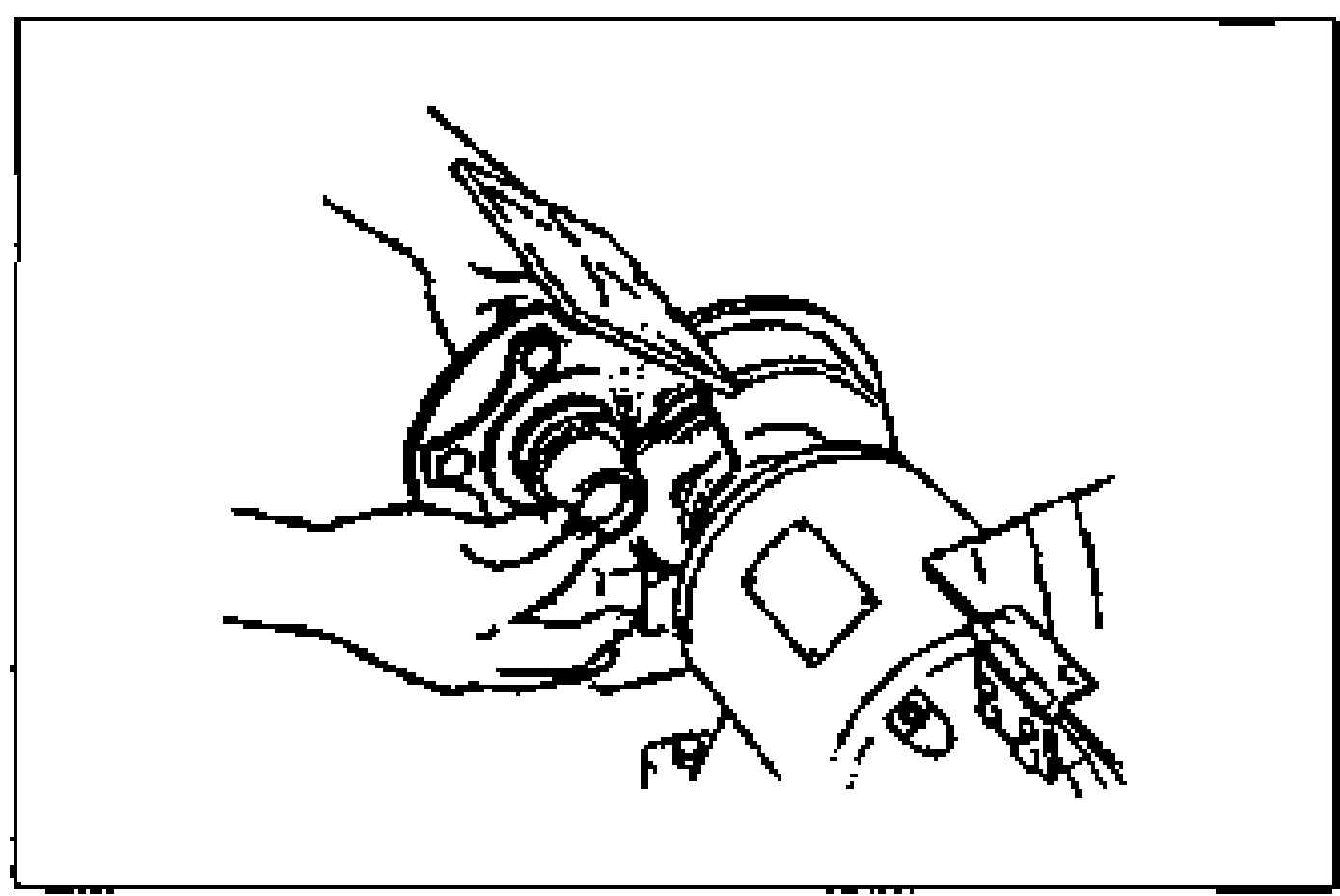
    Hand using a chisel on the front wheel hub assembly to remove the bearing inner race that remains after the hub is pressed out.

Search Manual

Search pages, specs, and procedures