Mazda MX-3 silhouetteMX-3

STARTING SYSTEM — STARTER

G-34prose procedure

B6 DOHC engine variant shown. Starter interlock switch applies to MTX (manual); transaxle range switch applies to ATX (automatic).

STARTER

Inspection (On-vehicle)

  1. 1
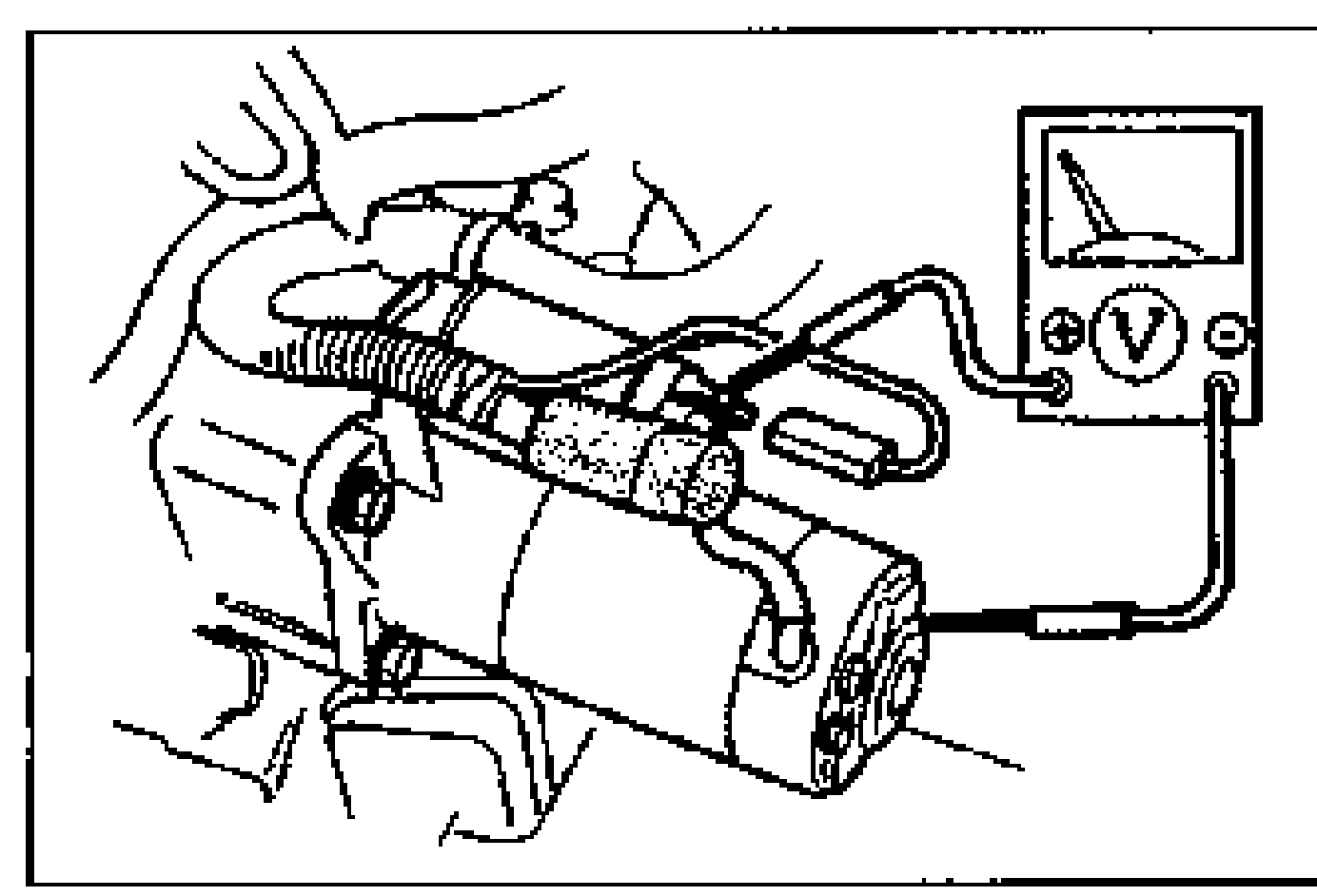
    Measure the battery positive voltage.
    On-vehicle voltage check of the starter. A voltmeter is connected to the starter terminal with the engine bay components in the background. Probes touch the starter terminal stud.
  2. 2
    Crank the engine, and verify that the starter turns smoothly.
  3. 3
    If the starter does not turn, check the voltage of terminal S.
  4. 4
    If the voltage is more than 8V, remove and inspect the starter. If the voltage is less than 8V, check the wiring harness, ignition switch, starter interlock switch (MTX) and transaxle range switch (ATX).
Battery positive voltageSpecification
Above 12.4V

Removal / Installation

  1. 1
    Remove in the order shown in the figure.
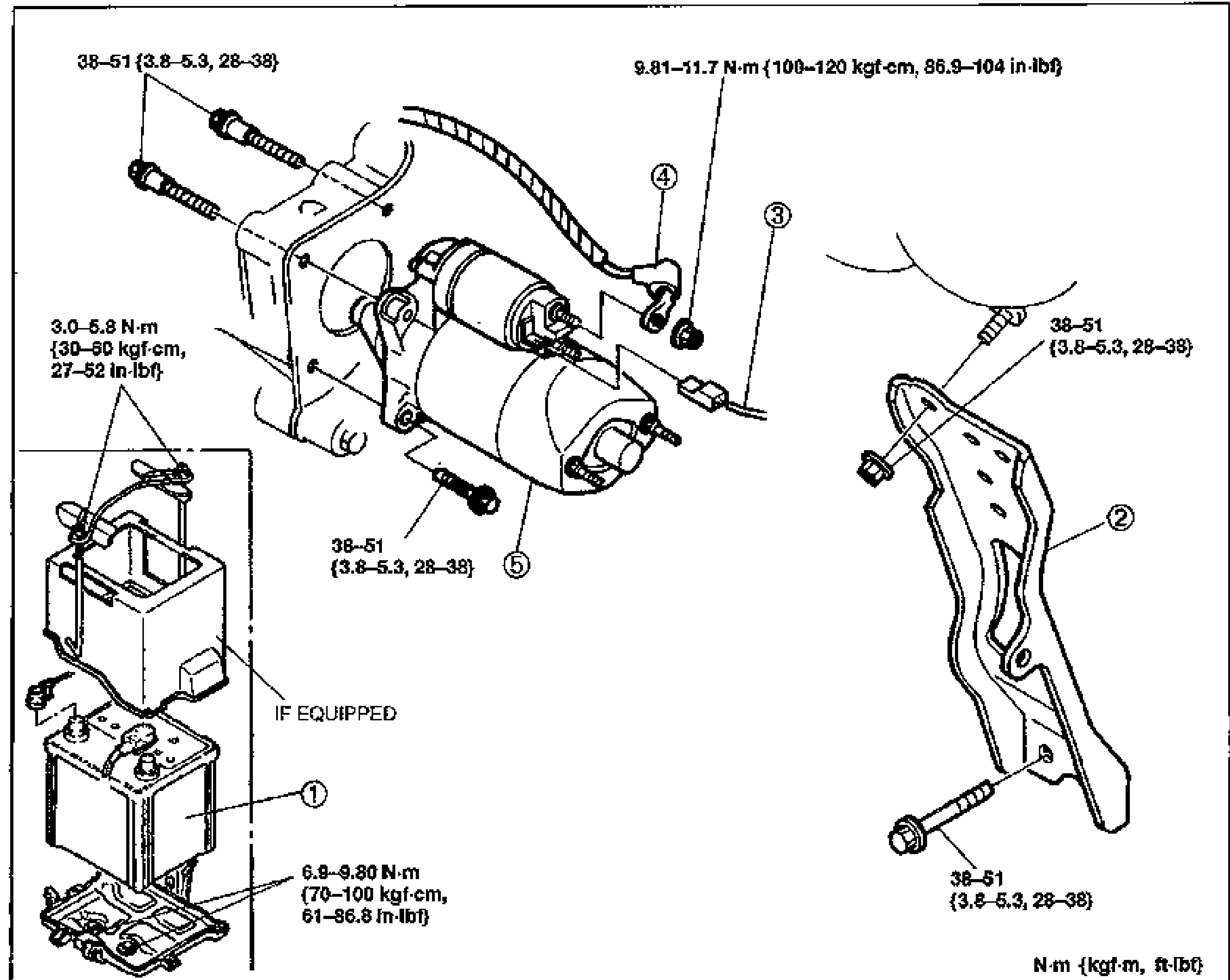
    Exploded view of the B6 DOHC starter mounting. Shows the battery (1) and battery tray, intake manifold bracket (2), terminal S wire (3), terminal B wire (4), and the starter (5). Tightening torques are called out at each fastener: 38-51 N·m {3.8-5.3 m-kg, 28-38 ft-lbf} for the starter/bracket bolts; 9.81-11.7 N·m {100-120 kgf-cm, 86.9-104 in-lbf} for terminal B; 3.0-5.8 N·m {30-60 kgf-cm, 27-52 in-lbf} for the small battery hold-down screws (if equipped); 6.9-9.80 N·m {70-100 kgf-cm, 61-86.8 in-lbf} for the battery base. Torque-unit legend N·m {kgf·m, ft-lbf}.
  2. 2
    Inspect all parts and repair or replace as necessary.
  3. 3
    Install in the reverse order of removal.

B6 DOHC

Parts DiagramFig. fig2
#Part NameNotes
1Battery
2Intake manifold bracket
3Terminal S wire
4Terminal B wire
5StarterDisassembly / Assembly ... page G-39; Inspection ... page G-40

Search Manual

Search pages, specs, and procedures