
REAR AXLE (Disc brake) — Locknut Removal/Installation Note; Disassembly / Assembly
M-16prose procedureDisc brake type rear axle (with ABS sensor rotor).
Removal Note
Locknut
- 1Knock the crimped portion of the locknut outward by using a small chisel and a hammer.
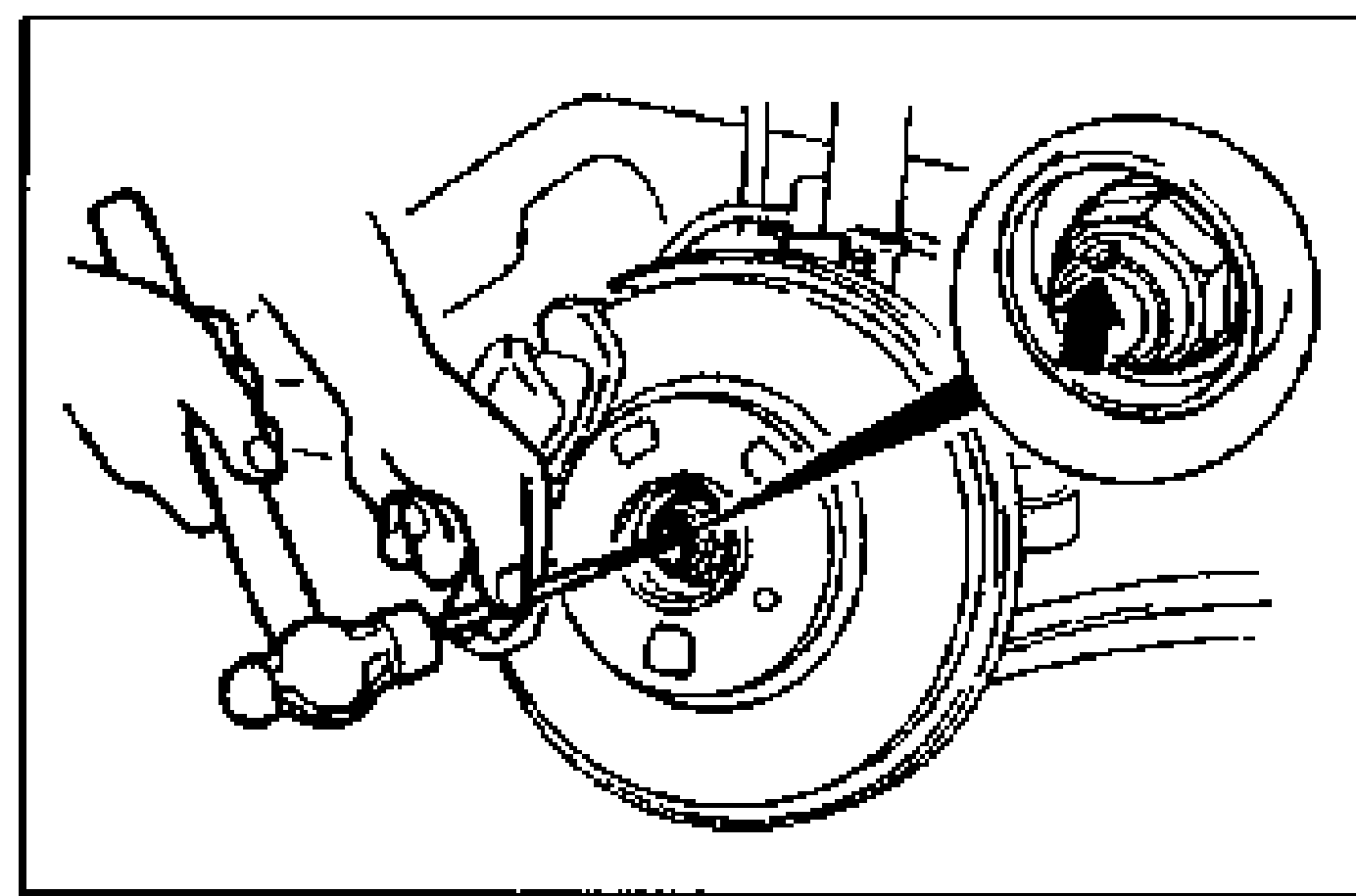
- 2Lock the hub by applying the brakes.
- 3Remove the locknut.
Installation Note
Locknut
Install a new locknut and stake it, as shown.
| Specification | Value |
|---|---|
| Tightening torque (locknut) | 177 - 235N·m |
Tightening torque (locknut)
177 - 235N·m
Disassembly / Assembly
- 1Disassemble in the order shown in the figure, referring to Disassembly Note.
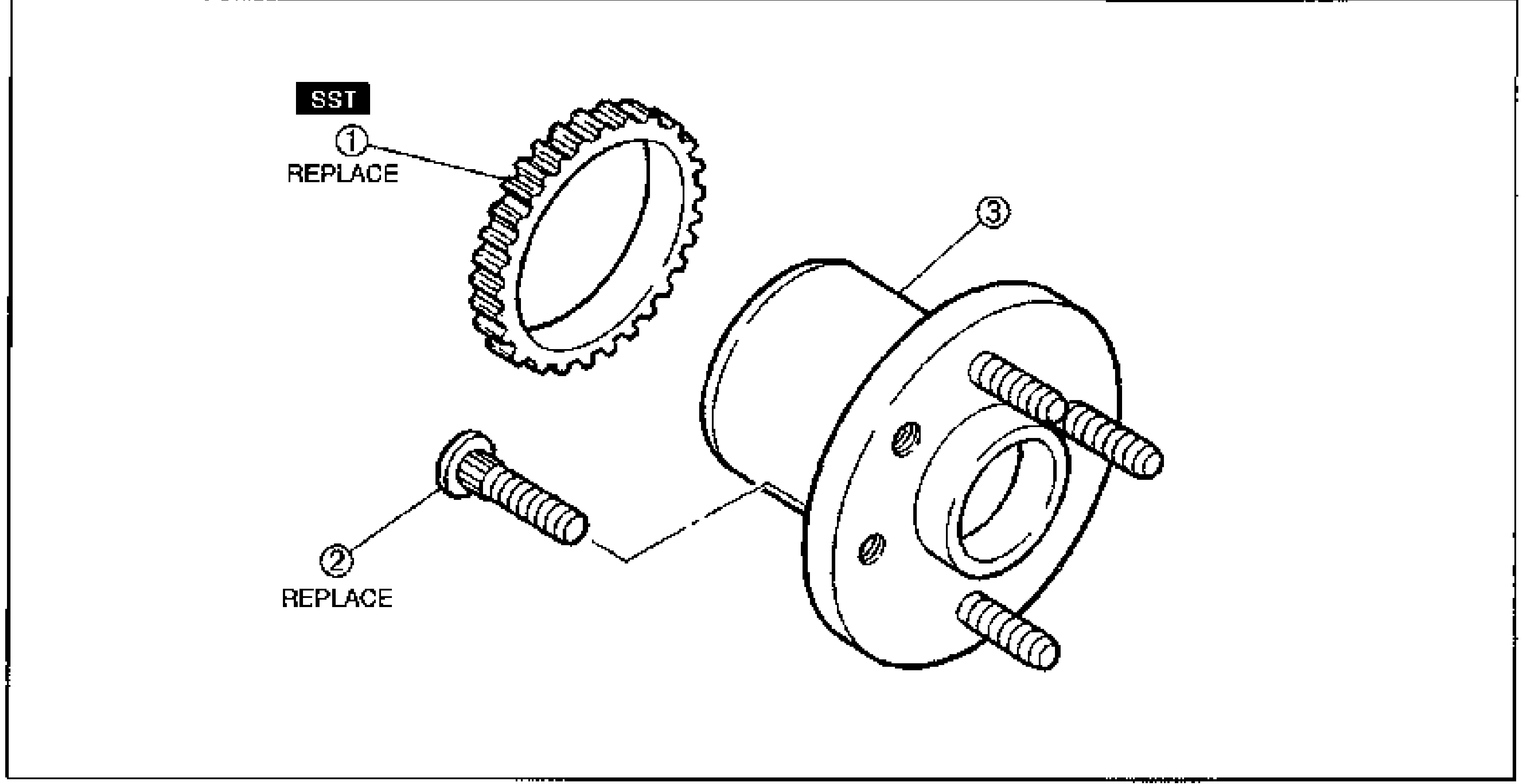
- 2Assemble in the reverse order of disassembly, referring to Assembly Note.
CAUTION
The wheel hub and bearing are one assembly and do not need to be disassembled.
Parts DiagramFig. fig3