
AIR CONDITIONER — Cooling Unit Disassembly / Assembly
G-68parts diagramDisassembly / Assembly
- 1Disassemble in the order shown in the figure.
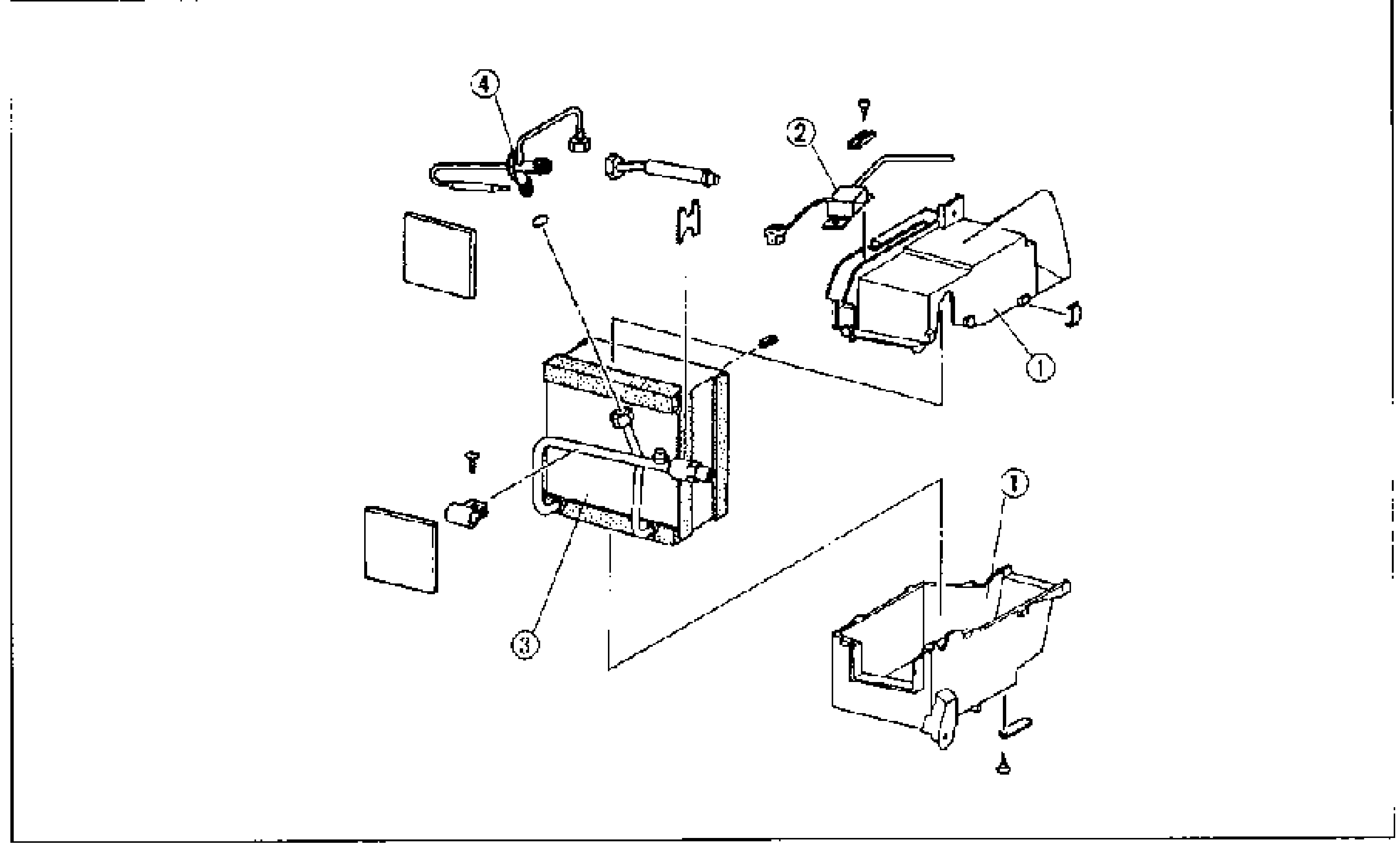
- 2Assemble in the reverse order of disassembly.
Parts DiagramFig. fig1
Replacement
Expansion valve
- 1Inspect the refrigerant system before replacing the expansion valve. (Refer to page G-53.)
- 2Remove the cooling unit. (Refer to page G-67.)
- 3Disassemble the cooling unit. (Remove the evaporator and expansion valve as an assembly.)
- 4Disconnect the inlet and outlet pipes.
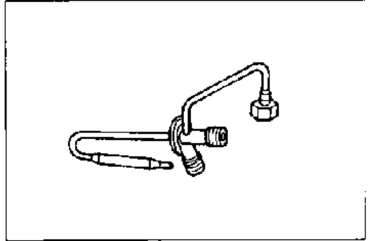
- 5Remove the heat-sensing tube from the outlet pipe and remove the expansion valve.
- 6Install in the reverse order of removal. Apply clean compressor oil to the O-rings before connecting the fittings.
| Specification | Value |
|---|---|
| Inlet pipe | 11.8—14.7N·m {120—150 kgf·cm, 105—130 in·lbf} |
| Outlet pipe | 30—34N·m {3.0—3.5 kgf·m, 22—25 ft·lbf} |
Inlet pipe
11.8—14.7N·m {120—150 kgf·cm, 105—130 in·lbf}
Outlet pipe
30—34N·m {3.0—3.5 kgf·m, 22—25 ft·lbf}