
ENGINE CONTROL MODULE (ECM)
F2-141prose procedureRemoval / Installation
- 1Remove in the order shown in the figure.
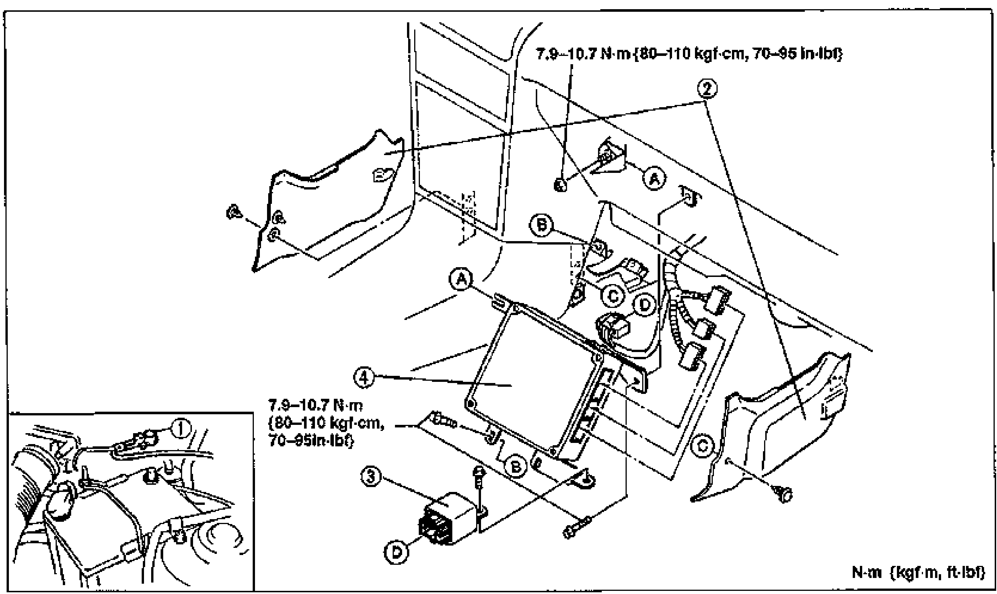
- 2Install in the reverse order of removal.
Parts DiagramFig. fig1
Inspection
- 1Disconnect the ECM connector.
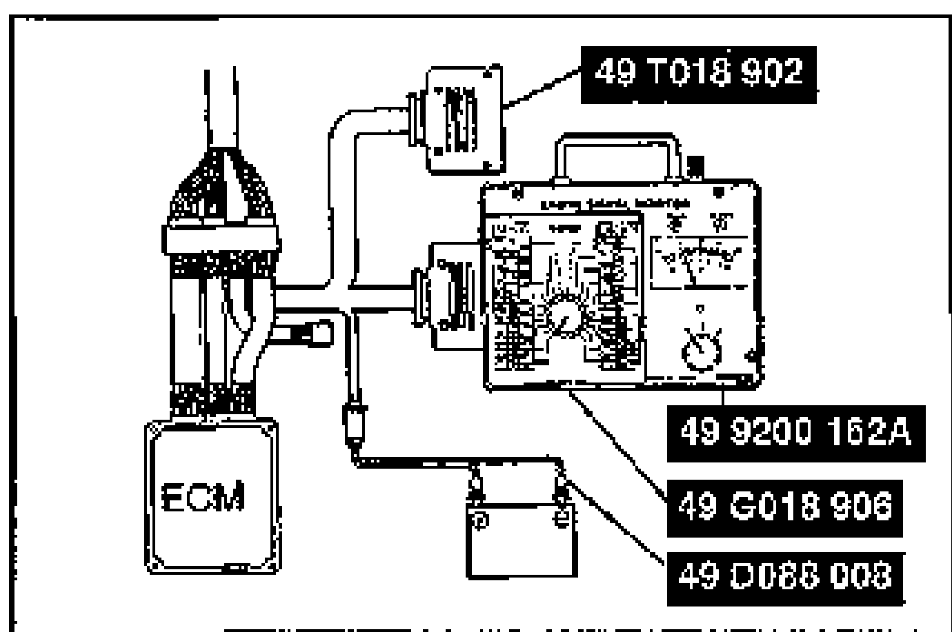
- 2Connect the SSTs (Engine Signal Monitor and Adapter) to the ECM as shown. Use connector A of the Adaptor to check the voltages at terminals 1A through 1V and at terminals 3A through 3Z. Use connector B to check the voltages at terminals 2A though 2P.
- 3Place the SST (Sheet) on the Engine Signal Monitor.
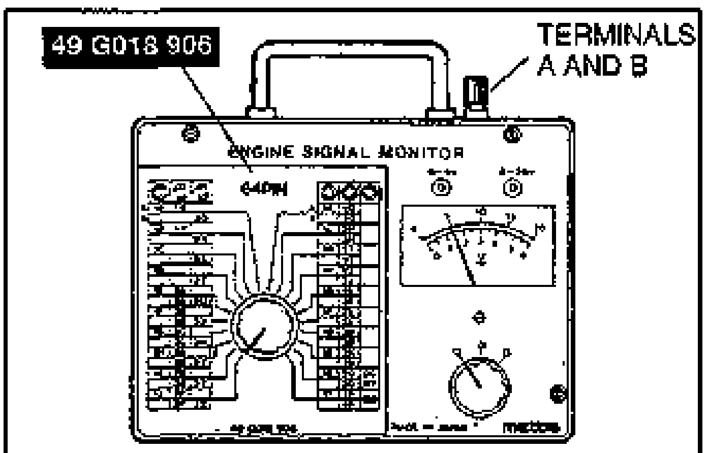
- 4Measure the voltage at each terminal. (Refer to pages F2-142 through F2-149.)
- 5If any ECM terminal voltage is incorrect, check the related input or output devices and wiring. If no problem is found, replace the ECM.