
AIR CONDITIONER — Condenser
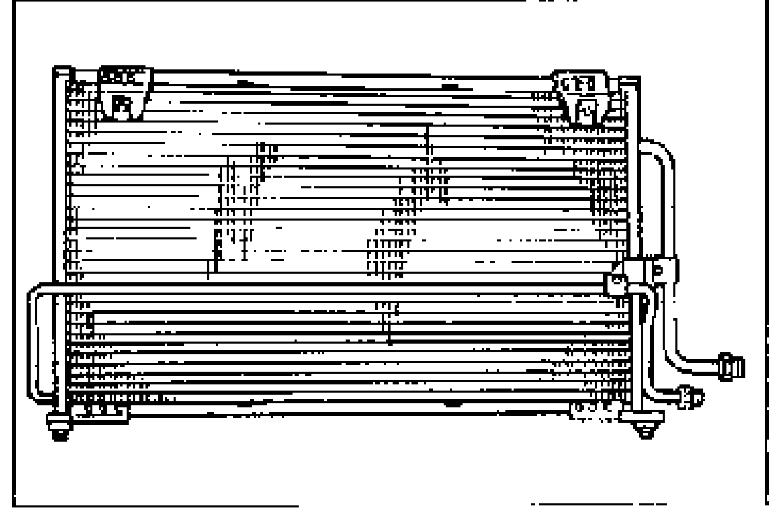
G-64parts diagramCONDENSER
Removal / Installation
- 1Discharge the refrigerant from the system.
- 2Remove the fresh-air duct.
- 3Remove the upper seal board.
- 4Disconnect the cooler pipes from the condenser.
- 5Insert a protector, such as cardboard, between the condenser and the radiator.
- 6Remove in the order shown in the figure.

- 7Install in the reverse order of removal. Apply clean compressor oil to the O-rings before connecting the fittings; do not apply compressor oil to the fitting nuts. When installing a new condenser, add 30 ml {30 cc, 1.0 fl oz} of compressor oil through the high-pressure-side of the A/C compressor.
| Specification | Value |
|---|---|
| Condenser inlet | 15—24N·m {1.5—2.5 kgf·m, 11—18 ft·lbf} |
| Condenser outlet | 10—19N·m {1.0—2.0 kgf·m, 8—14 ft·lbf} |
Condenser inlet
15—24N·m {1.5—2.5 kgf·m, 11—18 ft·lbf}
Condenser outlet
10—19N·m {1.0—2.0 kgf·m, 8—14 ft·lbf}
Parts DiagramFig. fig1
Inspection
Check for the following and repair or replace the condenser as necessary.
Inspection
- 1Cracks, damage, or refrigerant leakage
- 2Bent fins
- 3Distorted or damaged condenser inlet or outlet