Mazda MX-3 silhouetteMX-3

TIMING BELT

B2-13parts diagram

Timing belt diagram shown for K8-ZE V6 engine.

Removal / Inspection / Installation

  1. 1
    Disconnect the negative battery cable.
  2. 2
    Remove the right front wheel.
  3. 3
    Remove in the order shown in the figure, referring to Removal Note.
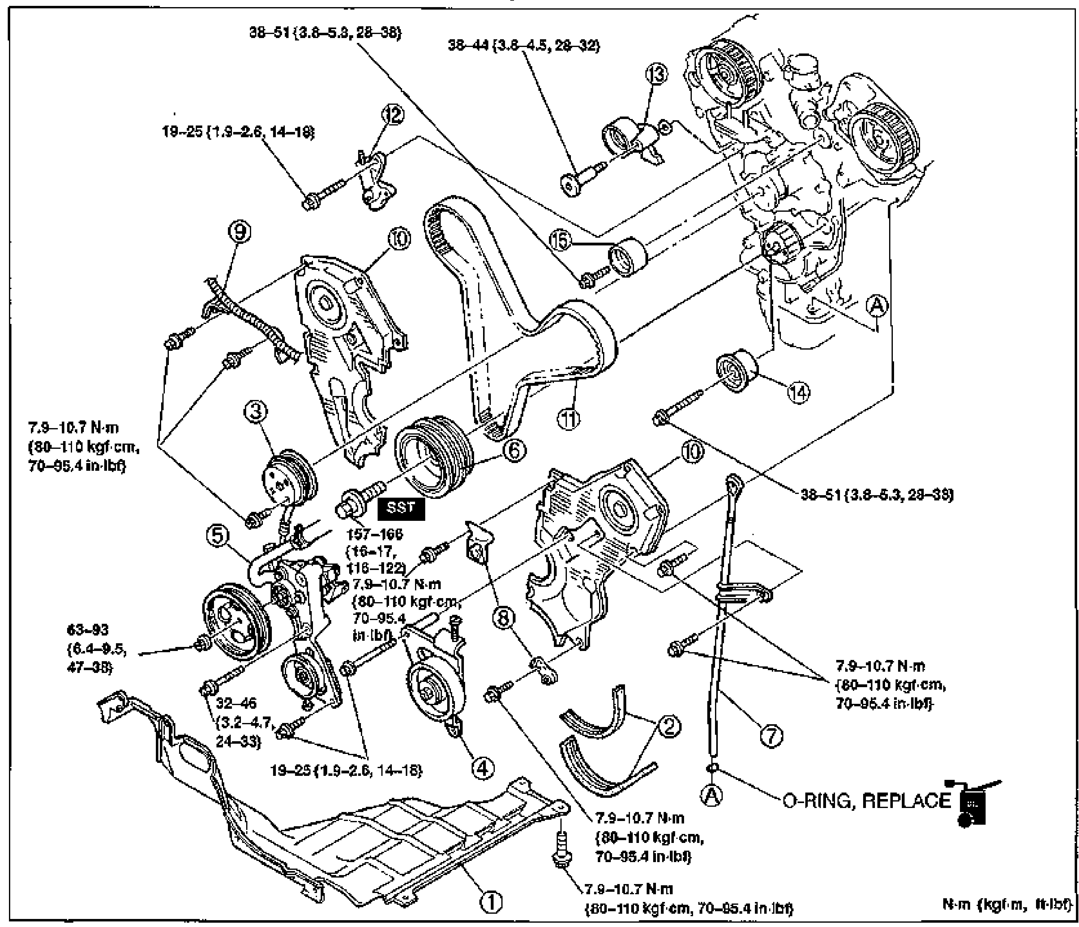
    Exploded view of the timing belt assembly and front engine covers (K8-ZE V6). Numbered balloon callouts 1-15 identify components in removal order, with tightening-torque annotations in N·m {kgf·cm/kgf·m, in-lbf/ft-lbf} at each fastener. An 'SST' label marks the crankshaft pulley holder location, and 'O-RING, REPLACE' is noted near the dipstick pipe (point A).
  4. 4
    Install in the reverse order of removal, referring to Installation Note.
Parts DiagramFig. fig1
#Part NameNotes
1Splash shield (RH)
2Drive beltRemoval / Installation: page B2-6
3Water pump pulley
4Idler pulley and bracket
5P/S oil pumpRemoval Note: page B2-14, Installation Note: page B2-21
6Crankshaft pulleyRemoval Note: page B2-15, Installation Note: page B2-21
7Dipstick and pipeRemoval Note: page B2-15, Installation Note: page B2-20
8Crankshaft position sensor harness bracket
9Engine harness bracket
10Timing belt coverRemoval Note: page B2-15, Installation Note: page B2-19
11Timing beltRemoval Note: page B2-16, Inspection: page B2-85, Installation Note: page B2-17
12Timing belt auto tensionerInspection: page B2-85, Installation Note: page B2-17
13Tensioner pulley
14No.2 idler pulley
15No.1 idler pulley

Search Manual

Search pages, specs, and procedures