Mazda MX-3 silhouetteMX-3

Clutch Unit

H-16parts diagram

Exploded view covers both B6 DOHC and K8 DOHC engines.

Removal / Installation

Removal / Installation

  1. 1
    Remove in the order shown in the figure, referring to Removal Note.
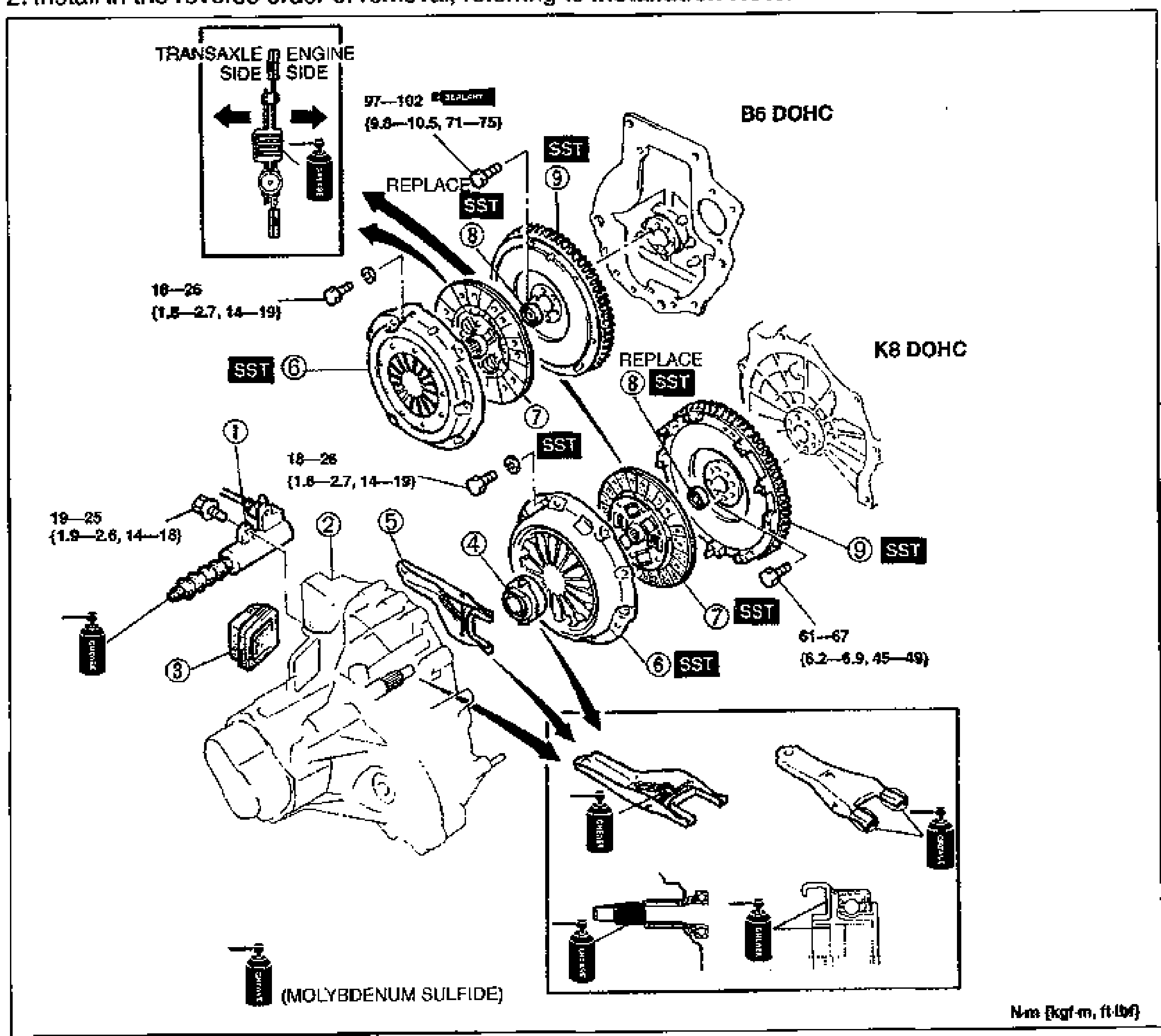
    Large exploded view of the clutch unit removal/installation for B6 DOHC and K8 DOHC engines. Numbered callouts 1-9: clutch release cylinder, transaxle, boot, clutch release collar, clutch release fork, clutch cover, clutch disc, pilot bearing, flywheel. SST markers and REPLACE indicators are shown at several joints. An inset top-left shows transaxle side vs engine side orientation with molybdenum sulfide grease application. Torque values: 97-102 N·m (9.8-10.5 kgf·m, 71-75 ft-lbf) for the flywheel, 18-26 N·m (1.8-2.7 kgf·m, 14-19 ft-lbf) and 19-25 N·m (1.9-2.6 kgf·m, 14-18 ft-lbf) at clutch fasteners, 61-67 N·m (6.2-6.9 kgf·m, 45-49 ft-lbf) at the K8 flywheel. Lower inset shows clutch release fork grease points (molybdenum sulfide).
  2. 2
    Install in the reverse order of removal, referring to Installation Note.
Parts DiagramFig. fig1
#Part NameNotes
1Clutch release cylinder
2TransaxleService ... sections J1, J2
3Boot
4Clutch release collarInspection ... page H-20
5Clutch release fork
6Clutch coverRemoval Note ... page H-17; Inspection ... page H-18; Installation Note ... page H-18
7Clutch discRemoval Note ... page H-17; Inspection ... page H-19; Installation Note ... page H-18
8Pilot bearingInspection ... page H-20; Removal Note ... page H-17; Installation Note ... page H-18
9FlywheelRemoval Note ... page H-17; Inspection ... page H-20; Installation Note ... page H-17

Search Manual

Search pages, specs, and procedures