Mazda MX-3 silhouetteMX-3

A/C COMPRESSOR — Disassembly / Assembly

G-56parts diagramUnverified

Disassembly / Assembly

Preparation SST

SST (Special Service Tools)

49 B061 005
NameReplacer, seal plate
UsageFor replacement of shaft seal plate
49 B061 005
NameRemover and installer, seal
UsageFor replacement of shaft seal

A/C Compressor Disassembly / Assembly

  1. 1
    Disassemble in the order shown in the figure.
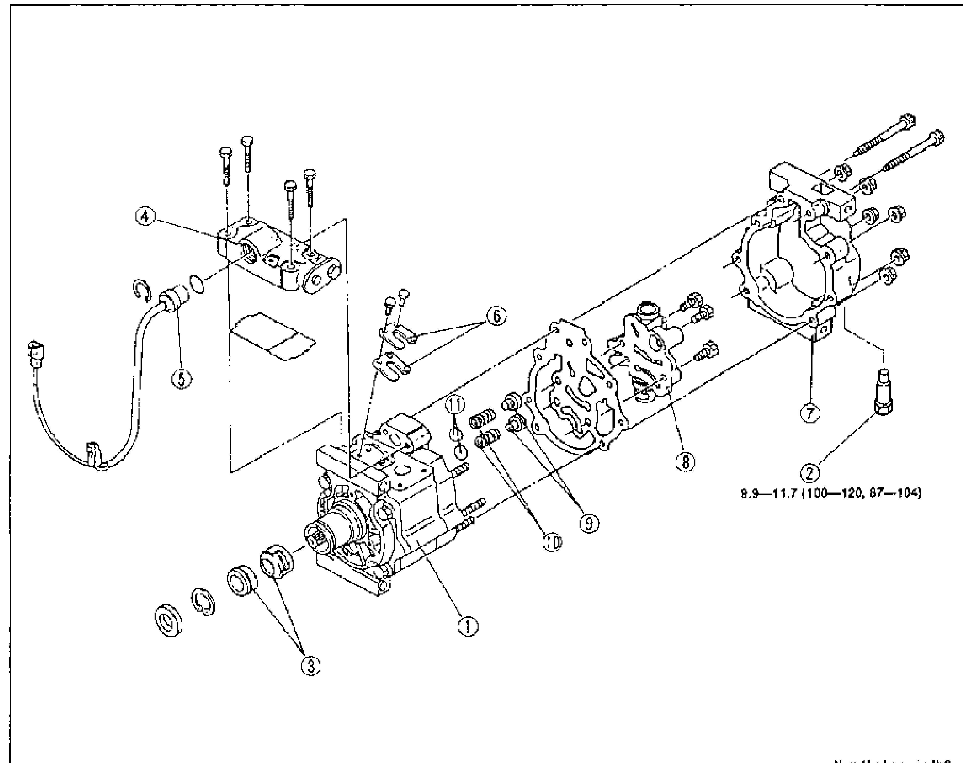
    Exploded view of the A/C compressor laid out horizontally with numbered balloon callouts 1-11 from front (shaft seal end, left) to rear case (right). Bolts are torqued; the rear-case bolts show torque 8.9-11.7 N.m (100-120 kgf.cm, 87-104 in-lbf). Units note at bottom right: N.m {kgf.cm, in-lbf}.
  2. 2
    Assemble in the reverse order of disassembly.
Parts DiagramFig. fig2
#Part NameNotes
1Compressor body
2Pressure relief valve
3Shaft seal and seal plateDisassembly note page G-57; Assembly note page G-60
4Head coverAssembly note page G-59
5Thermal protectorDisassembly note page G-58; Assembly note page G-58
6Discharge valve and valve stopperAssembly note page G-58
7Rear case
8Oil control valve
9Spring stopper
10Compression spring
11Anti-valve
Rear case bolt
87 - 115N·m

Search Manual

Search pages, specs, and procedures