
Power Brake Unit - Removal / Installation (K8 DOHC)
P-29parts diagramRemoval/Installation procedure is for K8 DOHC engine. Item 3 (Hose) is MTX only.
Removal / Installation (K8 DOHC)
- 1Remove in the order shown in the figure, referring to Removal Note.
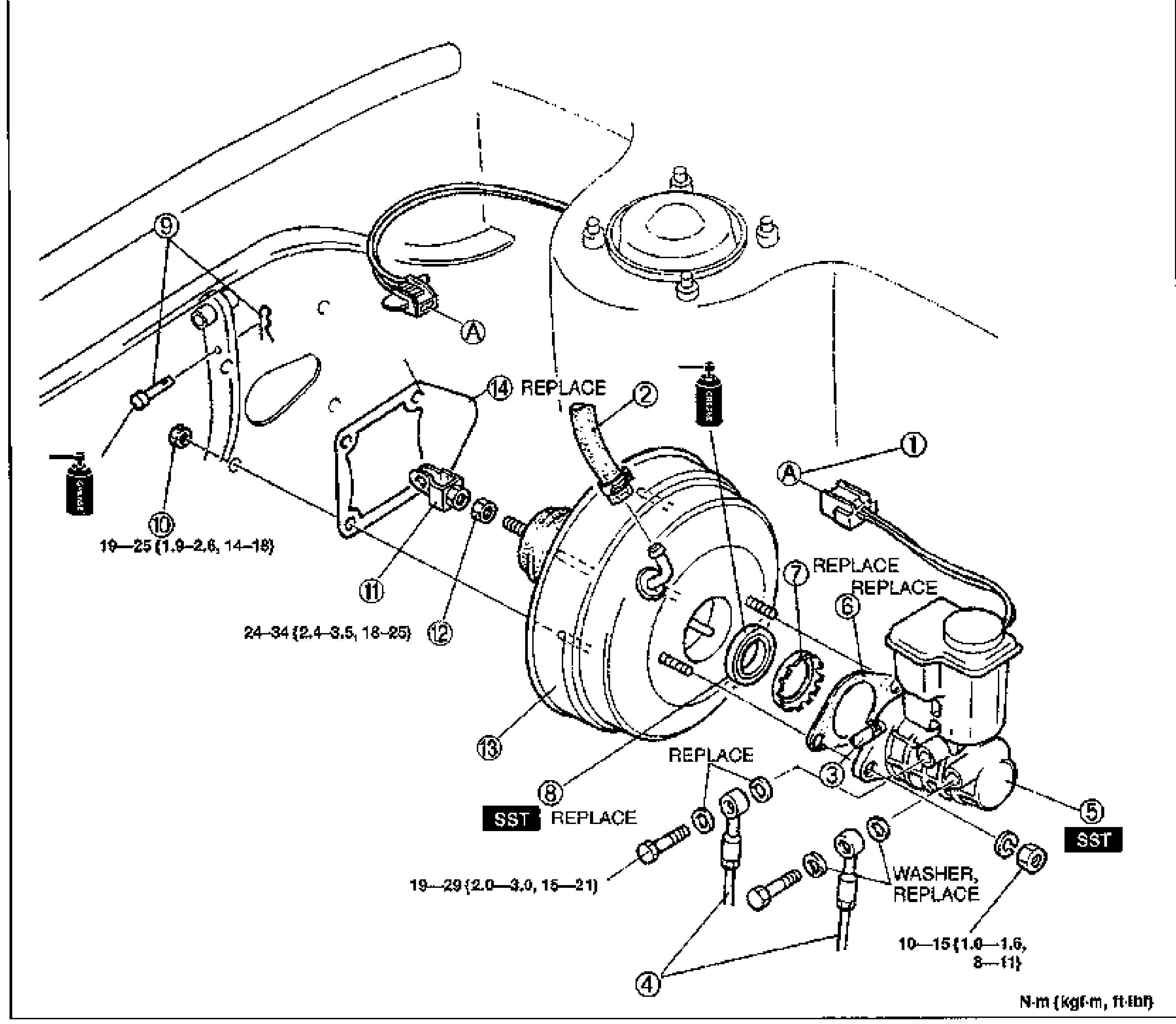
- 2Install in the reverse order of removal, referring to Installation Note.
- 3Take the following steps after installation: Add fluid and bleed the air. (Refer to page P-7.) Check all parts for fluid leakage. (Refer to page P-9.) Adjust and check the brake pedal. (Refer to page P-9.) Make an on-vehicle check of the unit. (Refer to page P-26.)Add fluid and bleed the air. (Refer to page P-7.)Check all parts for fluid leakage. (Refer to page P-9.)Adjust and check the brake pedal. (Refer to page P-9.)Make an on-vehicle check of the unit. (Refer to page P-26.)
Parts DiagramFig. fig1
| Specification | Value |
|---|---|
| Tightening torque (nut, item 10) | ≈186 - 245N·m |
| ≈186 - 284N·m | |
| Tightening torque (brake pipe area) | ≈98 - 147N·m |
Tightening torque (nut, item 10)
186 - 245N·m
186 - 284N·m
Tightening torque (brake pipe area)
98 - 147N·m