
INTAKE-AIR SYSTEM
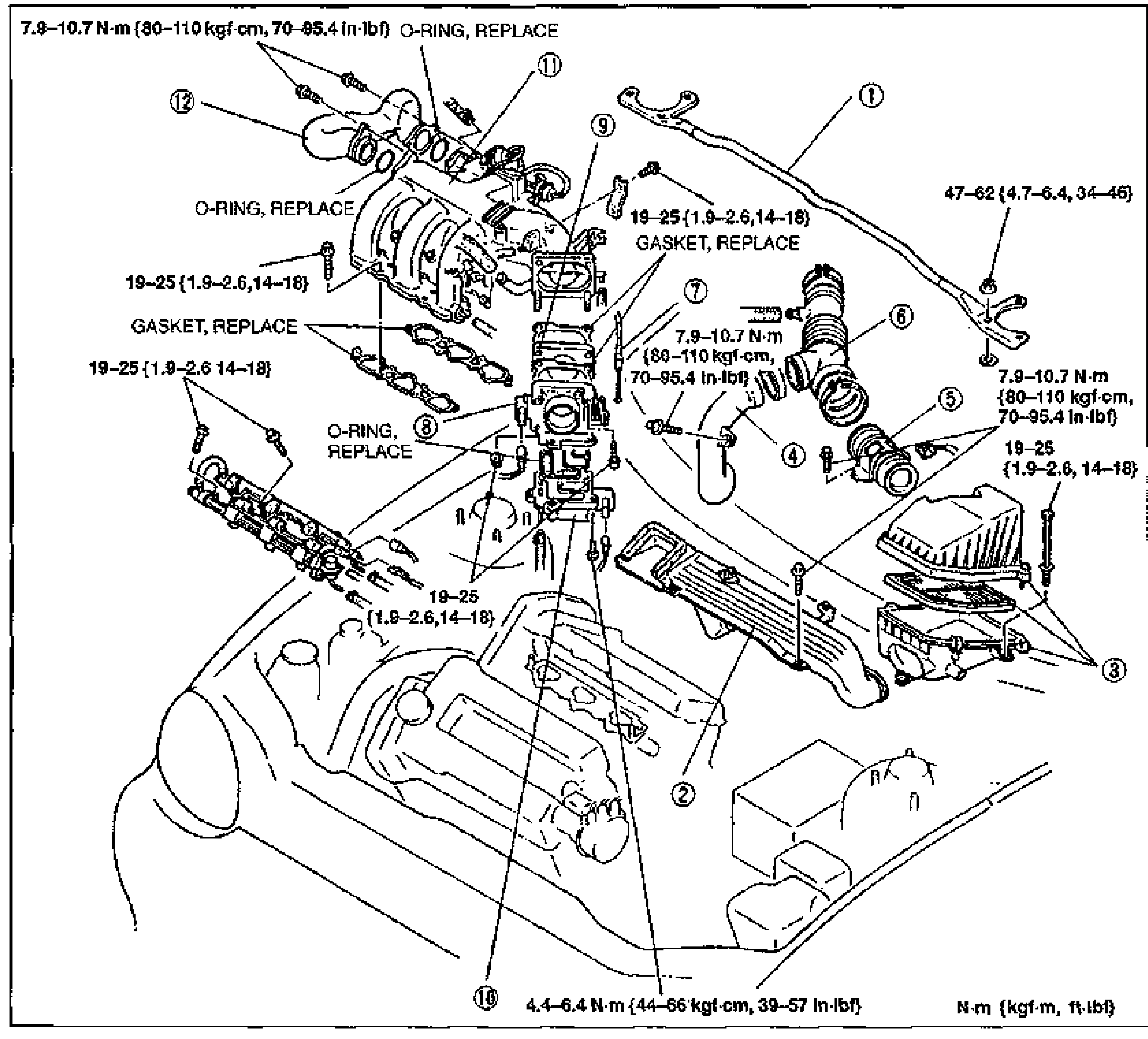
F2-95parts diagramCOMPONENTS
Removal / Inspection / Installation
- 1Remove in the order shown in the figure, referring to Removal Note.
- 2Check the components for damage and repair or replace as necessary.
- 3Install in the reverse order of removal, referring to Installation Note.
Parts DiagramFig. fig1
| Specification | Value |
|---|---|
| Tightening torque (O-ring fasteners)O-RING, REPLACE | ≈77 - 105N·m |
| Tightening torque (intake manifold / general)GASKET, REPLACE at joints | ≈186 - 245N·m |
| Tightening torque (strut bar mounting) | ≈461 - 608N·m |
| Tightening torque (BAC valve area) | ≈43 - 63N·m |
Tightening torque (O-ring fasteners)O-RING, REPLACE
77 - 105N·m
Tightening torque (intake manifold / general)GASKET, REPLACE at joints
186 - 245N·m
Tightening torque (strut bar mounting)
461 - 608N·m
Tightening torque (BAC valve area)
43 - 63N·m