
CONVENTIONAL BRAKE SYSTEM
P-14parts diagramHose item (3) is MTX (manual transaxle) only. This procedure is for ABS-equipped vehicles.
Removal / Installation / Inspection (ABS)
- 1Remove in the order shown in the figure, referring to Removal Note.
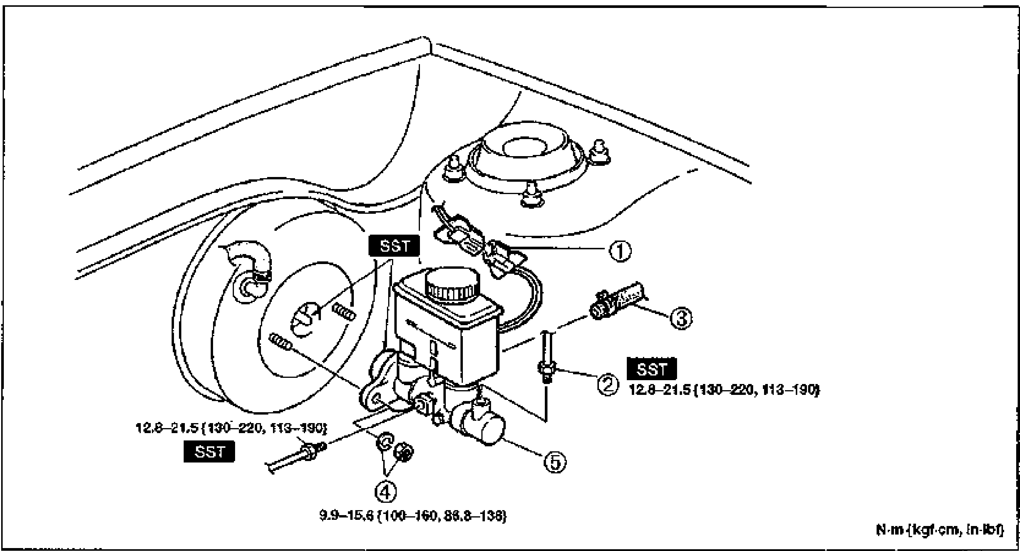
- 2Install in the reverse order of removal, referring to Installation Note.
- 3After installation, add brake fluid, bleed air, and check for fluid leakage.
Parts DiagramFig. fig1
Installation Note
Master cylinder — Push rod clearance
Inspect the push rod clearance as follows.
Push rod clearance inspection
- 1Turn the nut of the SST clockwise to fully retract the SST gauge rod. Attach the SST to the power brake unit.Tightening torque: 9.9–15.6 N·m {100–160 kgf·cm, 86.8—138 in·lbf}
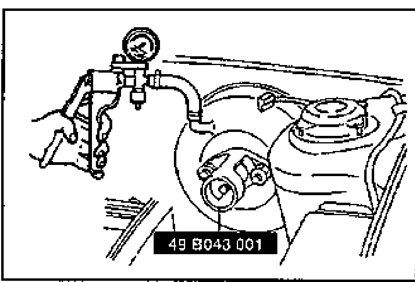 49 B043 001
 - 2Apply 66.7 kPa {500 mmHg, 19.7 inHg} vacuum using a vacuum pump.
- 3Turn the adjusting nut of the SST counterclockwise until the gauge rod just contacts the push rod end of the power brake unit. Push lightly on the end of the gauge rod to be sure it is seated. Verify that there is no gap between the adjusting nut and SST body.
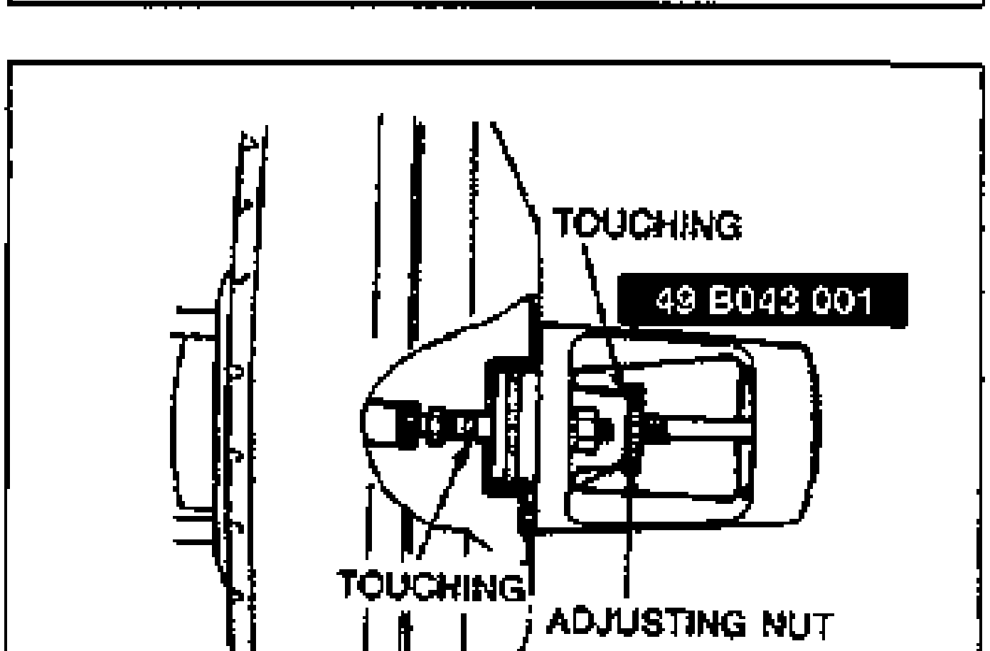 49 B043 001
| Specification | Value |
|---|---|
| SST attachment to power brake unit | 9.9 - 15.6N·m |
SST attachment to power brake unit
9.9 - 15.6N·m