Mazda MX-3 silhouetteMX-3

CLUTCH PEDAL

H-7parts diagram

Removal / Installation

  1. 1
    Remove in the order shown in the figure.
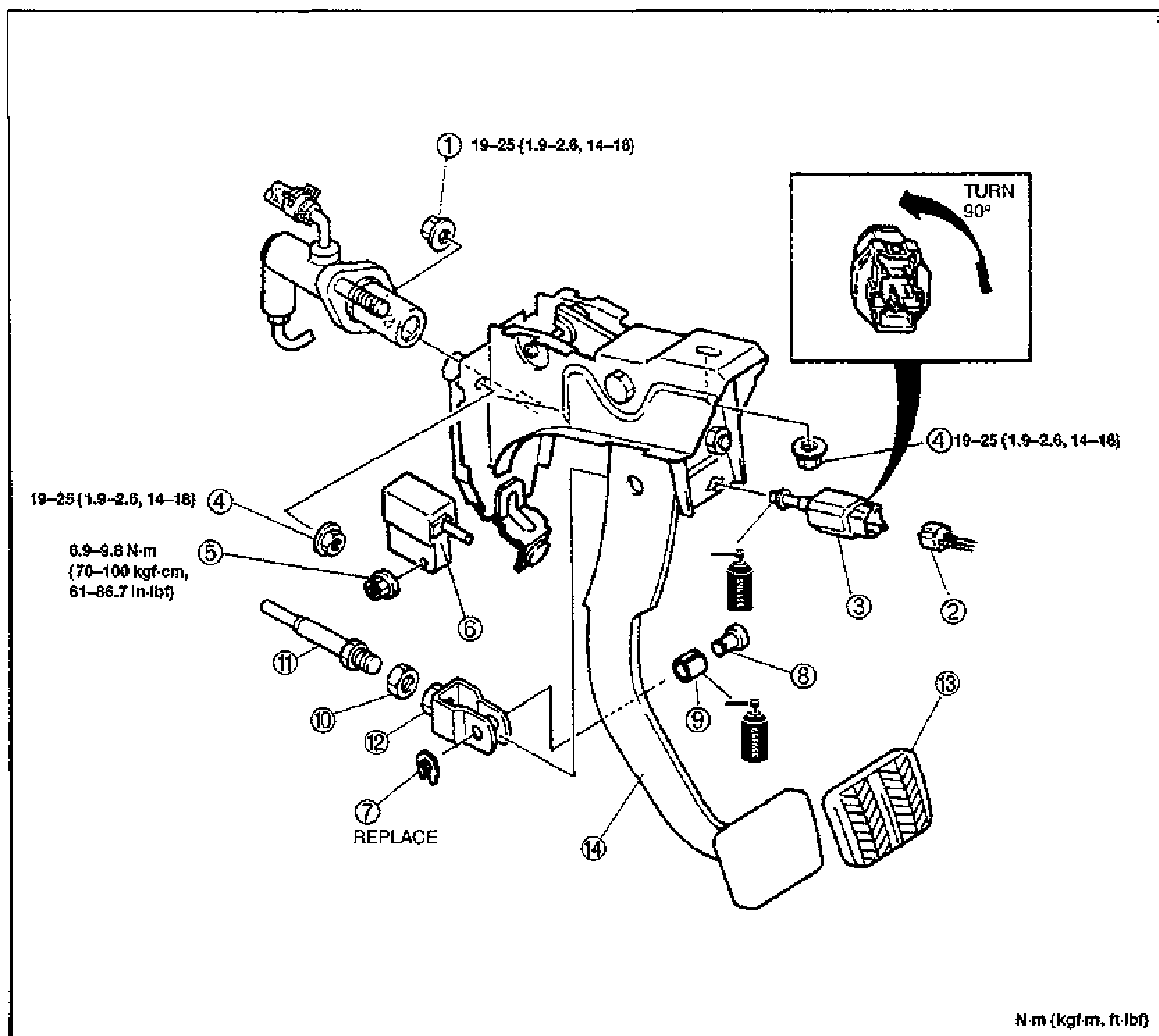
    Exploded view of the clutch pedal assembly with the pedal bracket. Numbered balloons 1-14 identify the master cylinder mounting nuts, clutch switch and connector, starter interlock switch, push rod, clevis, pin, clip, bushing, pedal pad and clutch pedal. An inset at upper right shows the clutch switch with a 'TURN 90°' rotation arrow for installation. Torque callouts: nuts (1) and (4) 19—25 N·m {1.9—2.6 kgf·m, 14—18 ft·lbf}; nut (5) 6.9—9.8 N·m {70—100 kgf·cm, 61—86.7 in·lbf}. Grease symbols indicate lubrication points; clip (7) marked REPLACE. Torque unit note: N·m {kgf·m, ft·lbf}.
  2. 2
    Inspect all parts and repair or replace as necessary.
  3. 3
    Install in the reverse order of removal.
Parts DiagramFig. fig1
#Part NameNotes
1NutTightening torque 19—25 N·m {1.9—2.6 kgf·m, 14—18 ft·lbf}
2Clutch switch connector
3Clutch switchTurn 90° on installation
4NutTightening torque 19—25 N·m {1.9—2.6 kgf·m, 14—18 ft·lbf}
5NutTightening torque 6.9—9.8 N·m {70—100 kgf·cm, 61—86.7 in·lbf}
6Starter interlock switch
7ClipReplace
8Pin
9Bushing
10Nut
11Push rodInspect for damage and bending
12Clevis
13Pedal pad
14Clutch pedalAdjustment: page H-6

See also

Search Manual

Search pages, specs, and procedures