Mazda MX-3 silhouetteMX-3

ENGINE SPEED SENSING POWER STEERING — Disassembly / Inspection (K8 DOHC)

N-30parts diagram

K8 DOHC engine application. Several disassembly points (8, 9, 19, 21, 22, 23, 24, 25) require a special service tool (SST), as marked in the exploded view.

Disassembly / Inspection (K8 DOHC)

  1. 1
    Disassemble in the order shown in the figure, referring to Disassembly Note.
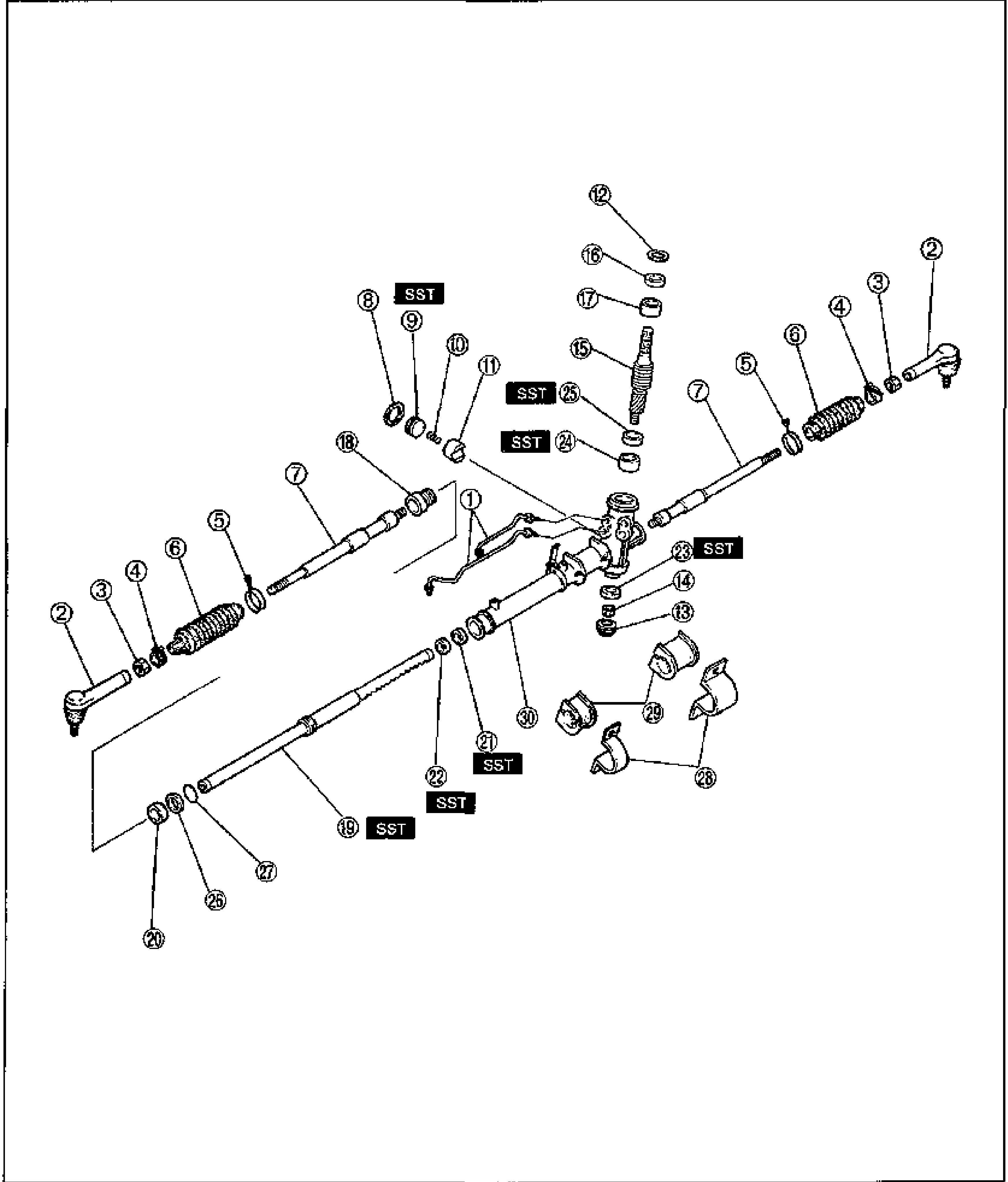
    Exploded view of the K8 DOHC engine-speed-sensing power steering gear assembly. Numbered balloons 1 through 30 identify components from the tie-rod ends and boots through the steering rack, pinion/valve assembly, mounting brackets and rubbers. Several positions are marked SST, indicating a special service tool is required at that step. Components shown include tie-rod ends, boots/boot bands, the rack, oil seals, bearings, the pinion shaft assembly with seal ring, mounting brackets and rubber bushings.
  2. 2
    Inspect all parts and repair or replace if necessary.
Parts DiagramFig. fig1
#Part NameNotes
1Oil pipes (cylinder pipe assembly)
2Tie-rod end
3Locknut / nut
4Clip / boot band
5Boot band
6Boot
7Tie rod
8WasherSST
9Washer / spacerSST
10Bushing
11Oil seal / O-ring
12Locknut
13Washer
14Plug / nut
15Adjusting cover
16Spring
17Support yoke
18Bearing
19Seal ringSST
20Plug
21Oil sealSST
22BearingSST
23Pinion / valve assemblySST
24Seal ringSST
25Seal ringSST
26Washer
27Bushing / spacer
28Mounting bracket
29Mounting rubber
30Gear housing / rack

Search Manual

Search pages, specs, and procedures