
OIL PAN
D2-8parts diagramREMOVAL / INSTALLATION
Oil pan removal / installation
- 1Disconnect the negative battery cable.
- 2Drain the engine oil. (Refer to page D2-5.)
- 3Remove in the order shown in the figure, referring to Removal Note.
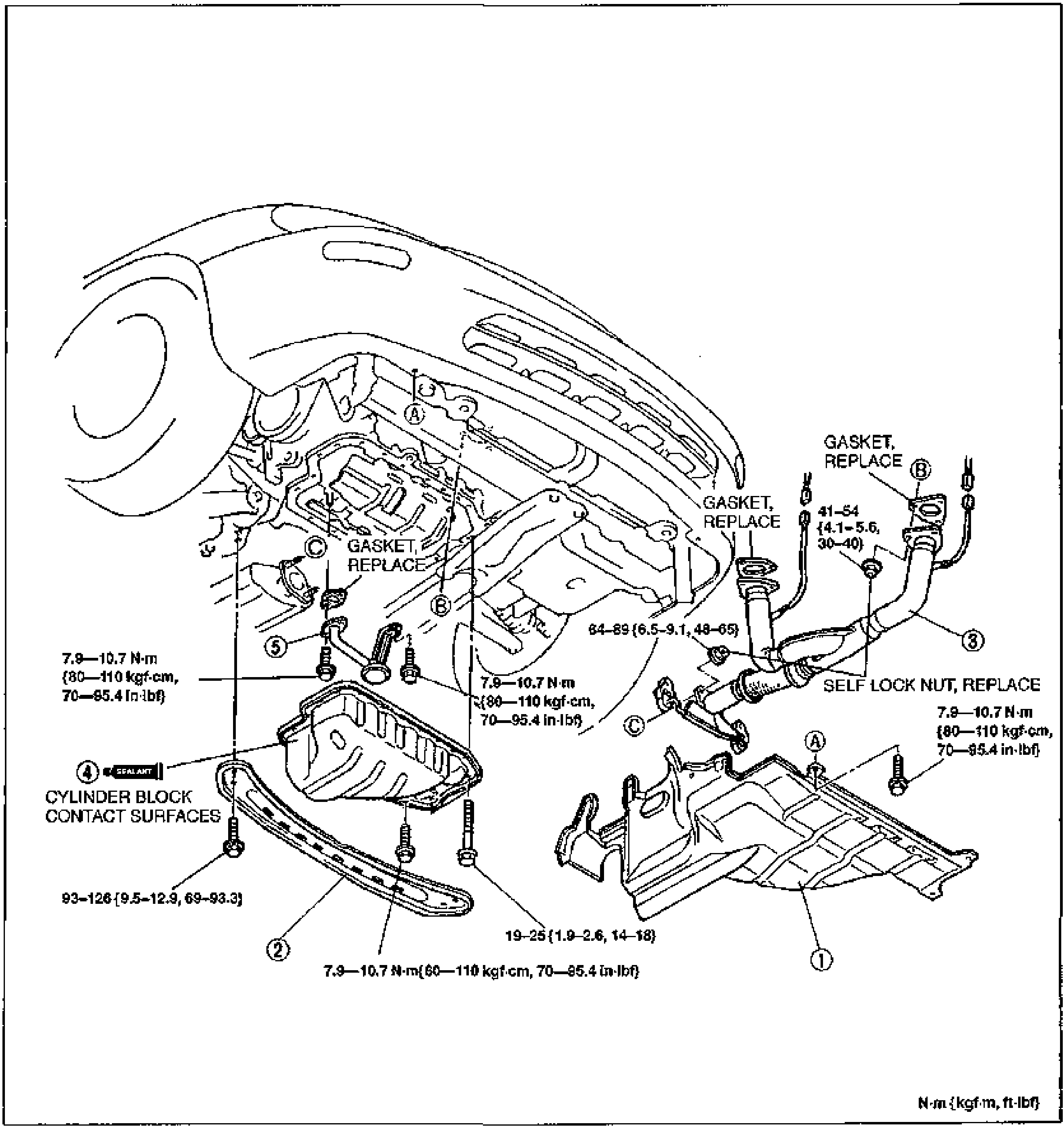
- 4Install in the reverse order of removal, referring to Installation Note.
Parts DiagramFig. fig1
| Specification | Value |
|---|---|
| Splash shield / oil pan / oil strainer bolt | 7.9–10.7N·m {80–110 kgf·cm, 70–95.4 in·lbf} |
| Oil pan bolt | 19–25N·m {1.9–2.6 kgf·m, 14–18 ft·lbf} |
| Transverse member bolt | 93–126N·m {9.5–12.9 kgf·m, 69–93.3 ft·lbf} |
| Front exhaust pipe | 64–89N·m {6.5–9.1 kgf·m, 48–65 ft·lbf} |
| Front exhaust pipe (self lock nut) | 41–54N·m {4.1–5.6 kgf·m, 30–40 ft·lbf} |
Splash shield / oil pan / oil strainer bolt
7.9–10.7N·m {80–110 kgf·cm, 70–95.4 in·lbf}
Oil pan bolt
19–25N·m {1.9–2.6 kgf·m, 14–18 ft·lbf}
Transverse member bolt
93–126N·m {9.5–12.9 kgf·m, 69–93.3 ft·lbf}
Front exhaust pipe
64–89N·m {6.5–9.1 kgf·m, 48–65 ft·lbf}
Front exhaust pipe (self lock nut)
41–54N·m {4.1–5.6 kgf·m, 30–40 ft·lbf}