
FRONT SUSPENSION (STRUT) — STABILIZER CONTROL LINK Removal / Inspection / Installation
R-24parts diagramSTABILIZER CONTROL LINK
Removal / Inspection / Installation
- 1Jack up the front of the vehicle and support it with safety stands.
- 2Remove the wheels.
- 3Remove in the order shown in the figure.
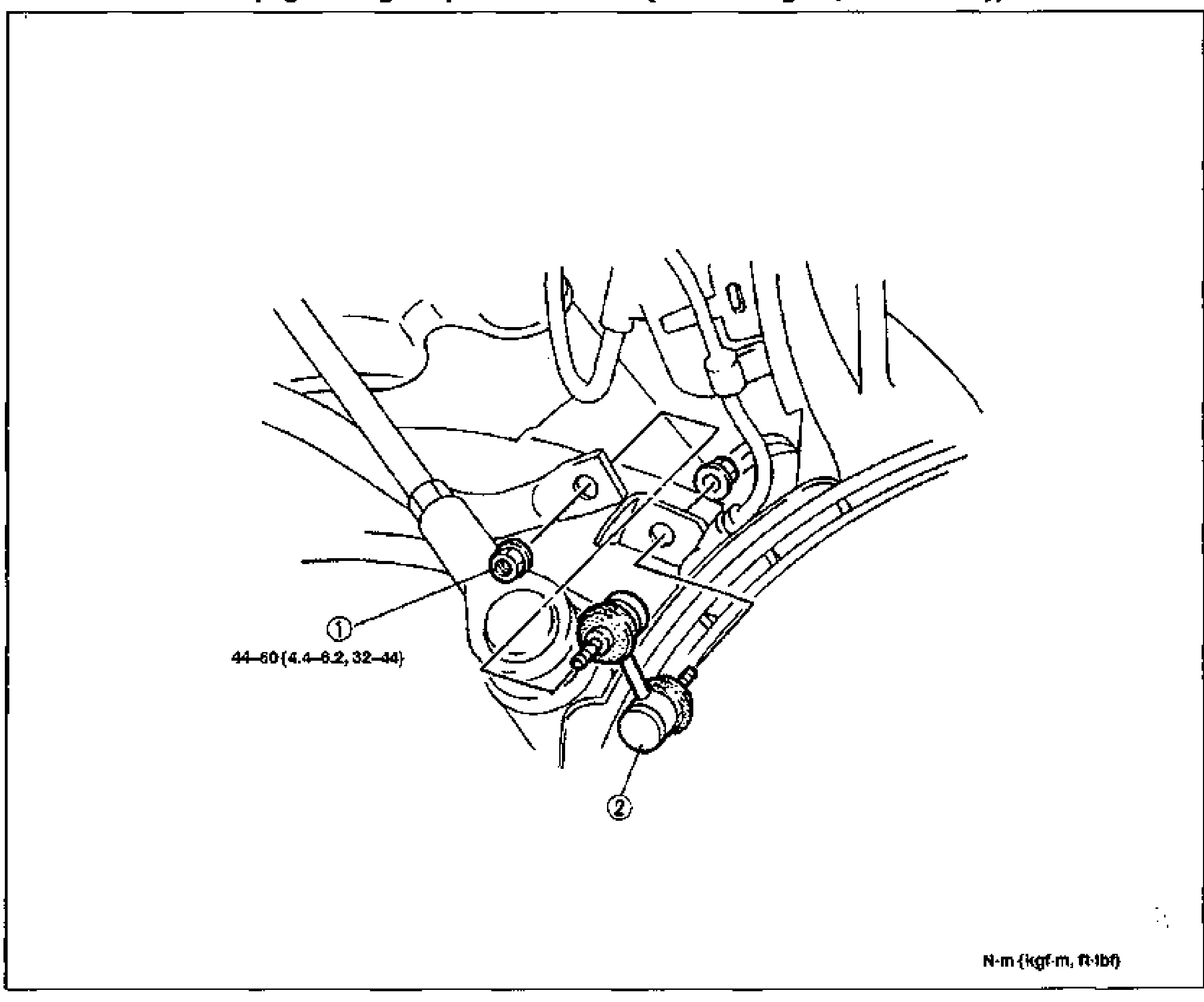
- 4Visually inspect each part and replace as necessary.
- 5Install in the reverse order of removal.
- 6Install the wheels. (Tightening torque: 89-117 N·m {9.0-12.0 kgf·m, 66-86 ft·lbf})
Parts DiagramFig. fig1
Inspection
Check the following and replace if necessary
Stabilizer control link
Stabilizer control link inspection
- 1Inspect for bending and damage.
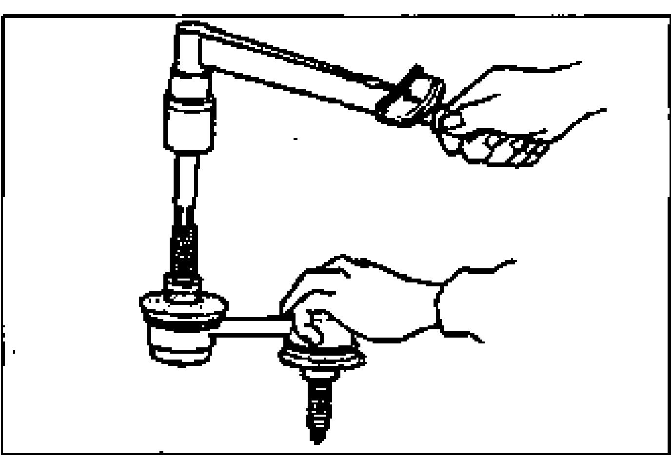
- 2Shake the ball joint stud 10 times.
- 3Rotate the ball joint stud 10 times.
- 4Measure the preload with a suitable hexagon wrench and torque wrench.
| Specification | Value |
|---|---|
| Preload | 0.2-1.4N·m {2.0-15.0 kgf·cm, 1.8-13.0 in·lbf} |
Preload
0.2-1.4N·m {2.0-15.0 kgf·cm, 1.8-13.0 in·lbf}