
Dual Proportioning Valve - Inspection, Replacement
P-30parts diagramFluid pressure differs for ABS, K8 DOHC (non ABS), and B6 DOHC (non ABS). Replacement diagram shows separate NON ABS MODEL and ABS MODEL valves.
Inspection
Dual Proportioning Valve Inspection
- 1Connect the SSTs to the brake pipes with adapters as shown in the figure.Connect the brake pipes with SST (49 0259 770B)
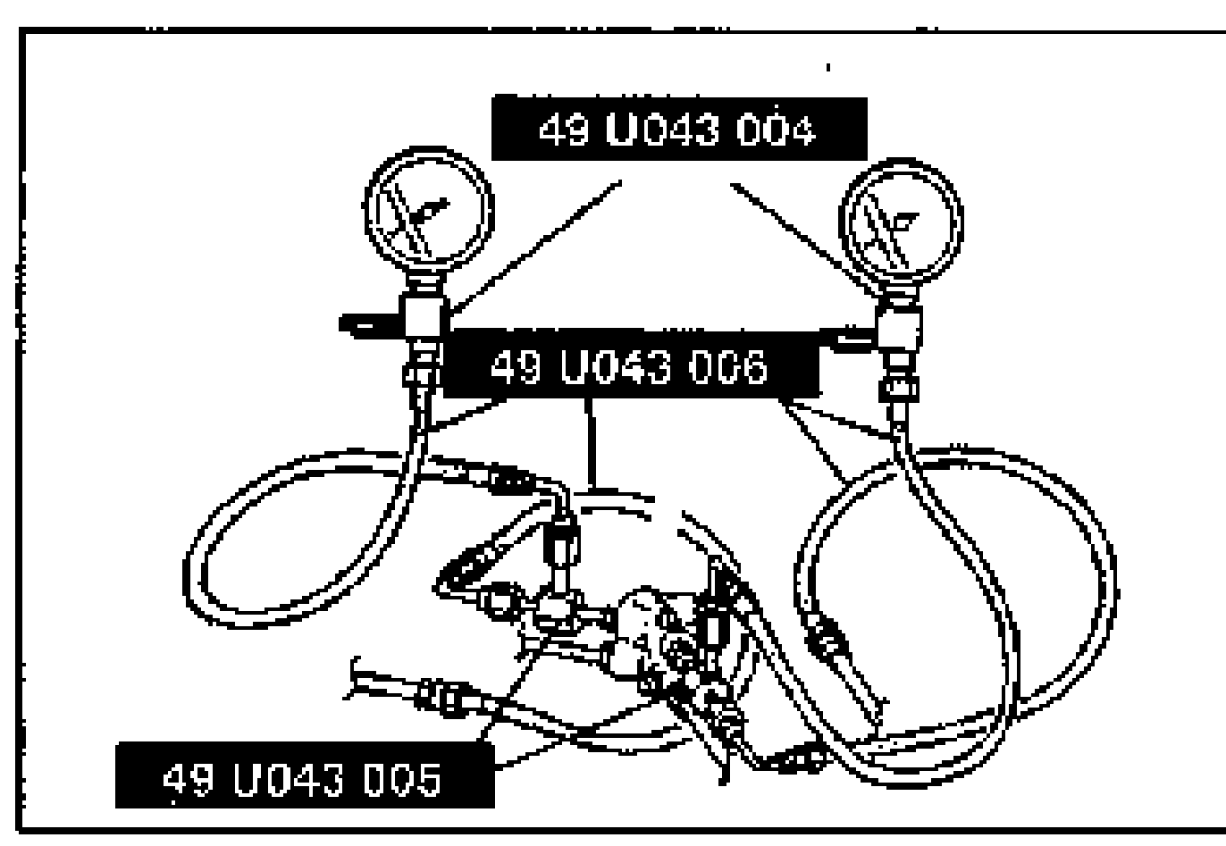
- 2Bleed the air from the brake system. (Refer to page P-7.)
- 3Depress the brake pedal until the master cylinder pressure equals A; then record rear brake pressure A'.
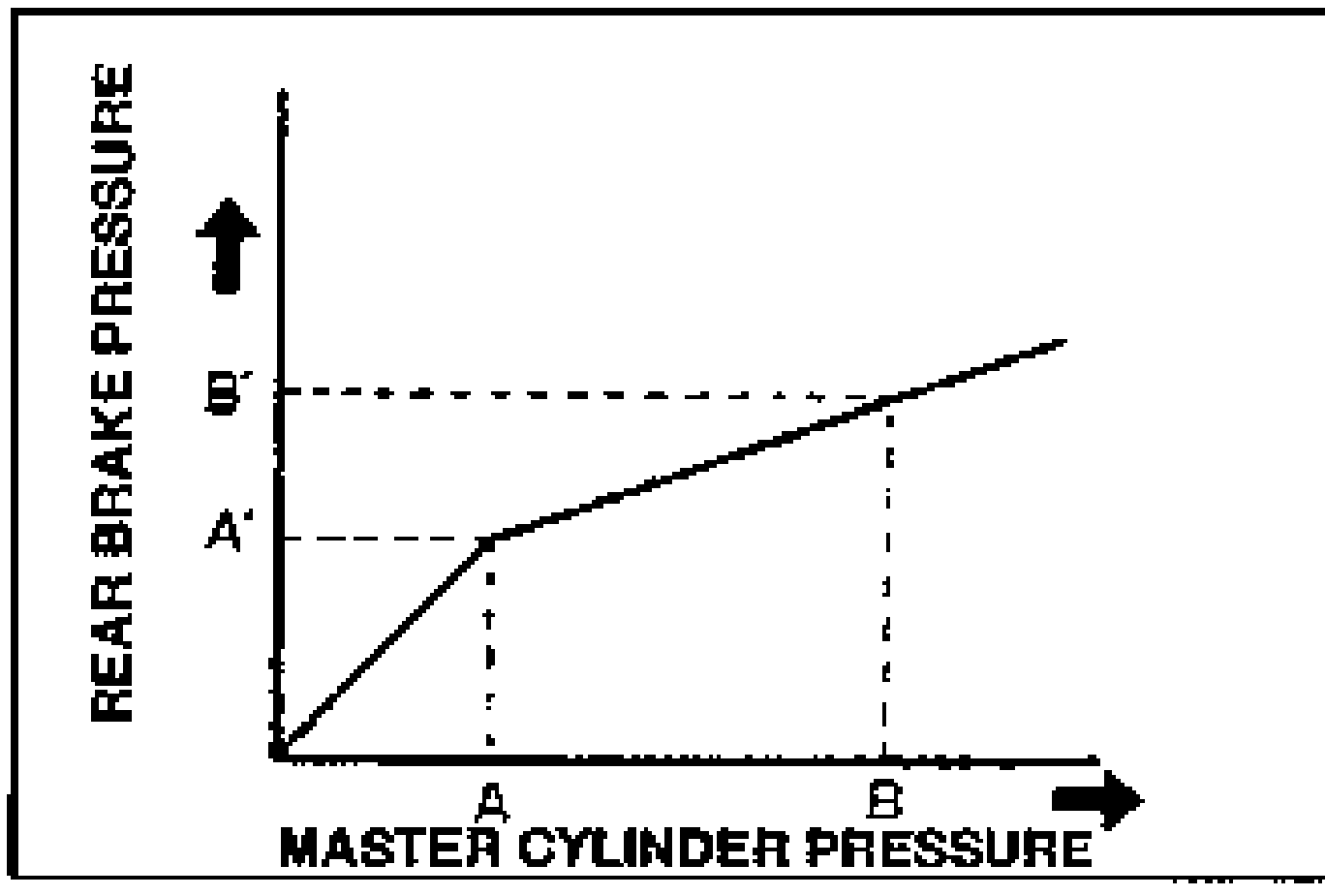
- 4Depress the brake pedal again, apply additional pressure until the pressure equals B; then record pressure B'.
| Specification | Value |
|---|---|
| Adapter and flare nut | ≈126 - 211N·m |
Adapter and flare nut
126 - 211N·m
Fluid pressure kPa {kgf/cm2, psi}
ABS
A2,453 {25,356}
A'2,453 {25,356} ±196 {2,28}
B5,886 {60,853}
B'3,826 {39,555} ±333 {3,43}
K8 DOHC (non ABS)
A2,453 {25,356}
A'2,453 {25,356} ±196 {2,28}
B5,886 {60,853}
B'3,138 {32,455} ±294 {3,43}
B6 DOHC (non ABS)
A2,943 {30,427}
A'2,943 {30,427} ±196 {2,28}
B5,886 {60,853}
B'3826 {39,555} ±284 {3,43}
Replacement
Dual Proportioning Valve Replacement
- 1Remove in the order shown in the figure, referring to Removal Note.
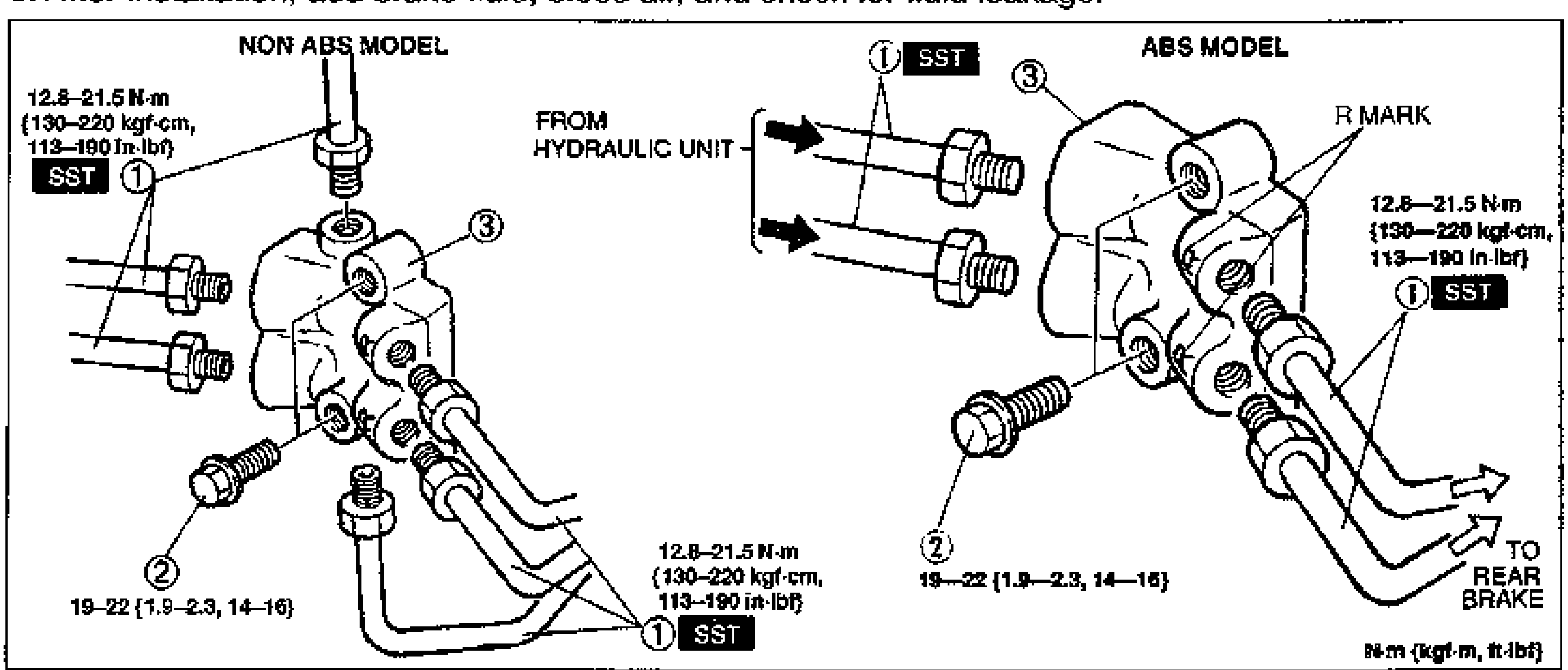
- 2Install in the reverse order of removal, referring to Installation Note.
- 3After installation, add brake fluid, bleed air, and check for fluid leakage.
Parts DiagramFig. fig3
| Specification | Value |
|---|---|
| Tightening torque (brake pipe, SST) | ≈126 - 211N·m |
| Tightening torque (bolt, item 2) | ≈186 - 216N·m |
Tightening torque (brake pipe, SST)
126 - 211N·m
Tightening torque (bolt, item 2)
186 - 216N·m