
Front Axle — Removal / Installation
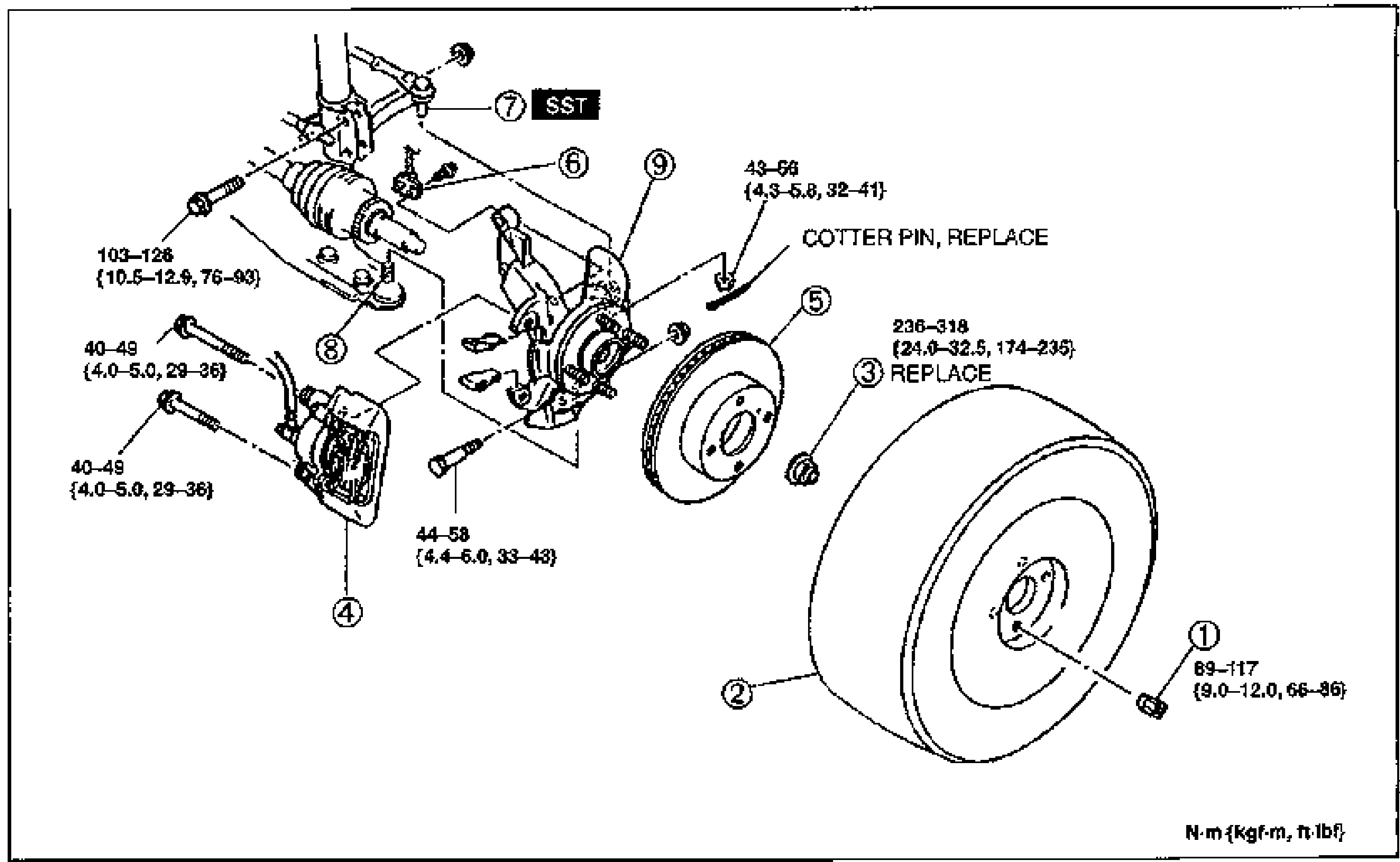
M-6parts diagramABS wheel-speed sensor present on ABS-equipped vehicles.
Removal / Installation
- 1Remove in the order shown in the figure, referring to Removal Note.
- 2Inspect all parts and repair or replace as necessary.
- 3Install in the reverse order of removal, referring to Installation Note.
- 4After installation, check the wheel alignment, referring to Section R.
Parts DiagramFig. fig1
| Specification | Value |
|---|---|
| Wheel nut (1) | 69—117N·m {9.0—12.0 kgf·m, 66—86 ft·lbf} |
| Locknut (3)REPLACE | 236—318N·m {24.0—32.5 kgf·m, 174—235 ft·lbf} |
| Tie-rod end (7) | 43—66N·m {4.3—6.8 kgf·m, 32—41 ft·lbf} |
| Lower ball joint (8) | 103—126N·m {10.5—12.9 kgf·m, 76—93 ft·lbf} |
| Bracket boltstwo locations on knuckle | 40—49N·m {4.0—5.0 kgf·m, 29—36 ft·lbf} |
| Bolt | 44—58N·m {4.4—6.0 kgf·m, 33—43 ft·lbf} |
Wheel nut (1)
69—117N·m {9.0—12.0 kgf·m, 66—86 ft·lbf}
Locknut (3)REPLACE
236—318N·m {24.0—32.5 kgf·m, 174—235 ft·lbf}
Tie-rod end (7)
43—66N·m {4.3—6.8 kgf·m, 32—41 ft·lbf}
Lower ball joint (8)
103—126N·m {10.5—12.9 kgf·m, 76—93 ft·lbf}
Bracket boltstwo locations on knuckle
40—49N·m {4.0—5.0 kgf·m, 29—36 ft·lbf}
Bolt
44—58N·m {4.4—6.0 kgf·m, 33—43 ft·lbf}
NOTE
COTTER PIN, REPLACE — replace the cotter pin at the tie-rod end.
Removal Note
Locknut
- 1Knock the crimped portion of the locknut outward by using a small chisel and hammer.
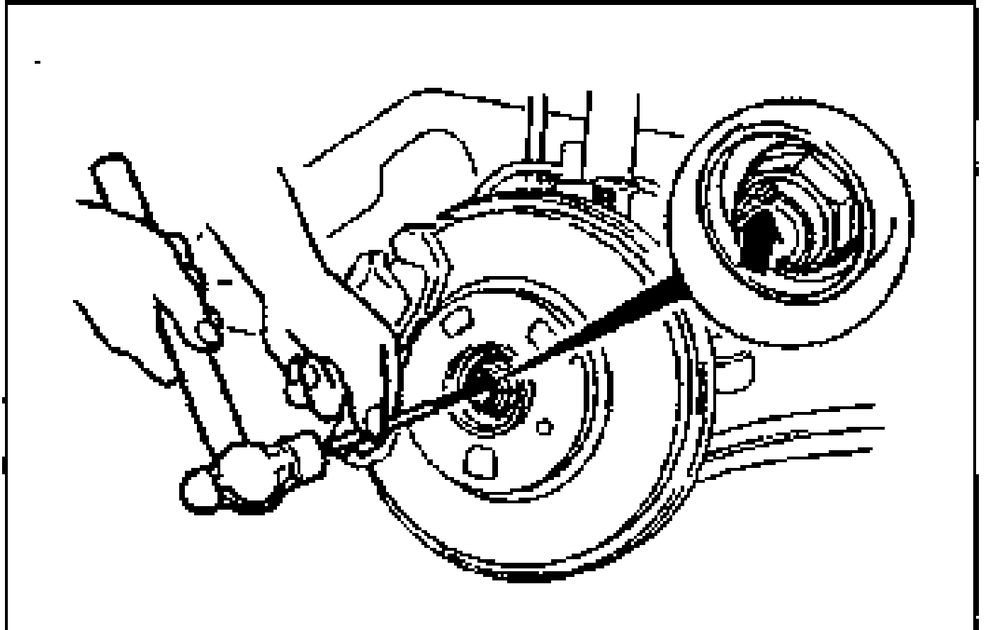
- 2Lock the hub by applying the brakes.
- 3Remove the locknut.