
Power Brake Unit - Check Valve Inspection, Removal/Installation (B6 DOHC)
P-28parts diagramRemoval/Installation procedure is for B6 DOHC engine. Item 10 (Gasket, spacer) is ATX model only.
Check Valve
Inspection
Check Valve Inspection
- 1Remove the clamps and the vacuum hose.
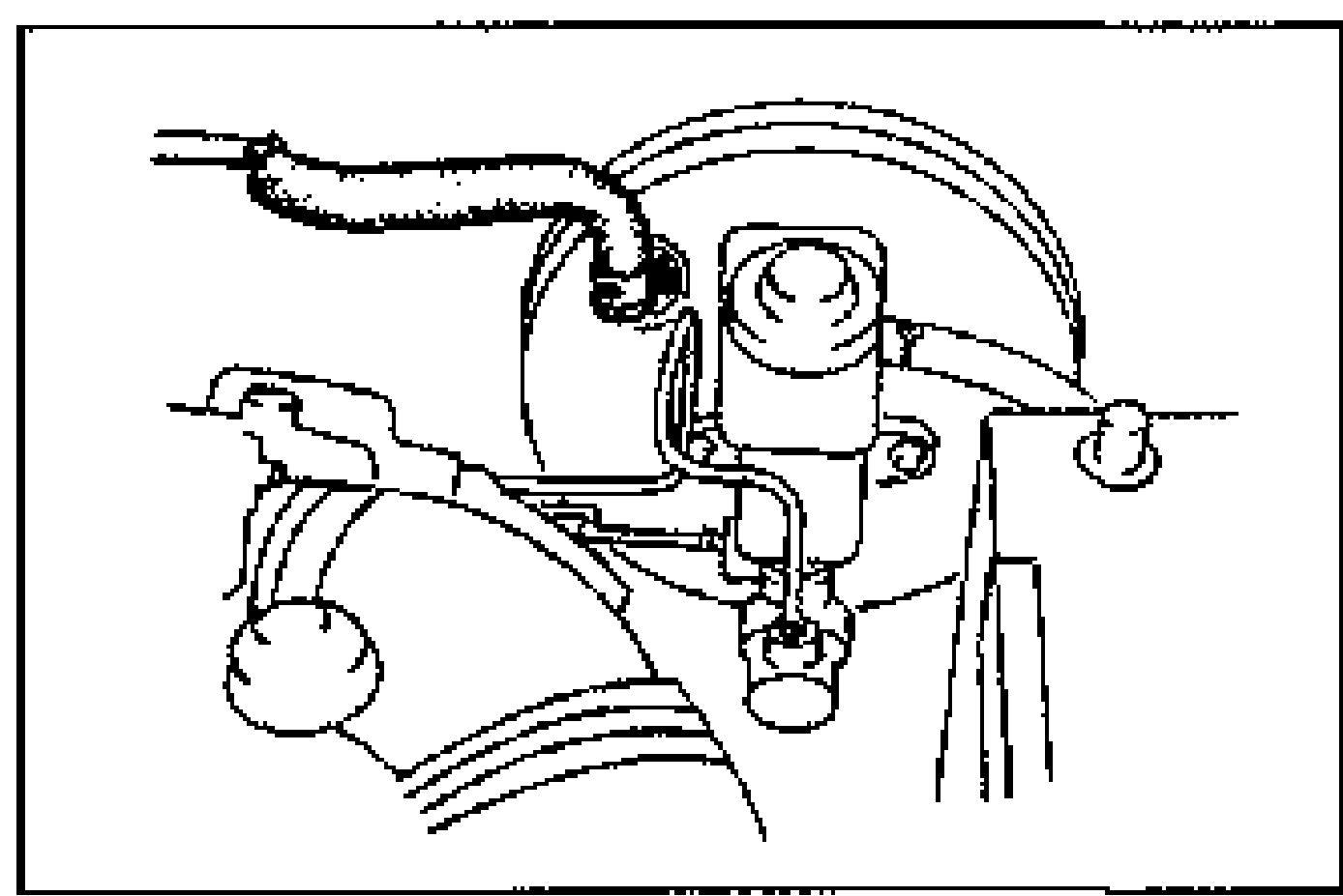
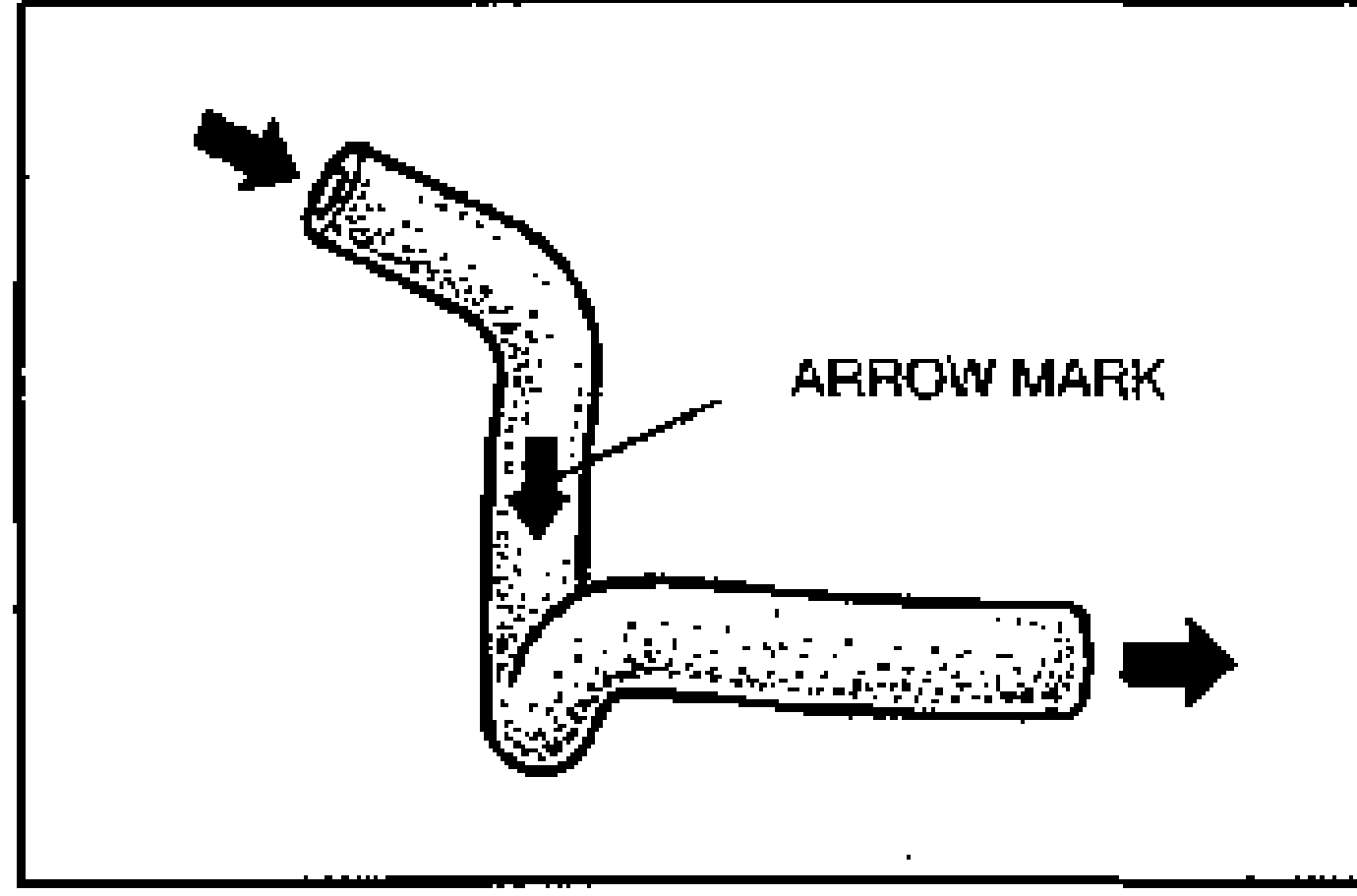
- 2Apply both suction and pressure to the engine-side of the hose, and verify that air flows only toward that side. If air flows in both directions or not at all, replace the vacuum hose.
Removal / Installation (B6 DOHC)
- 1Remove in the order shown in the figure, referring to Removal Note.
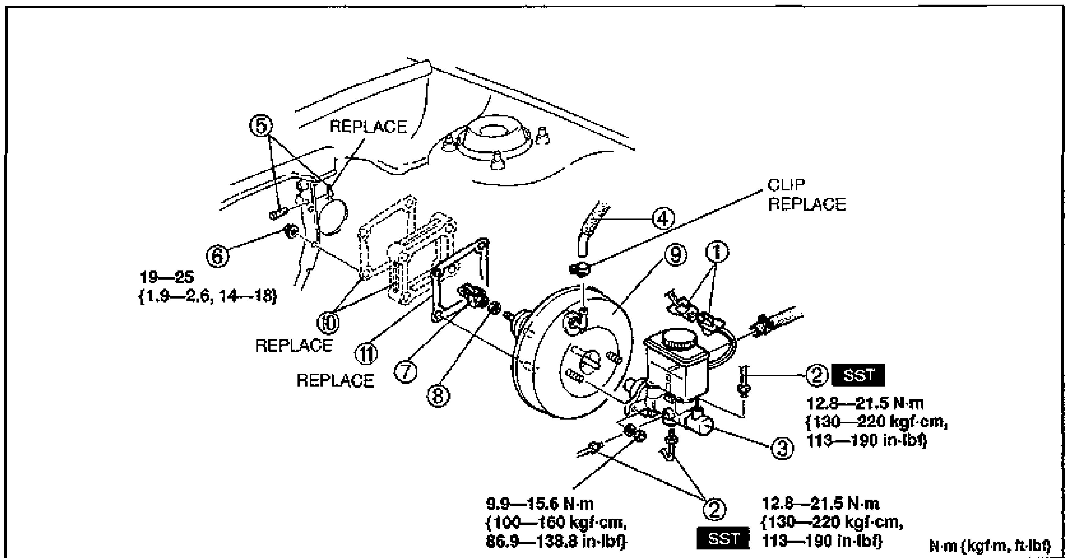
- 2Install in the reverse order of removal, referring to Installation Note.
Parts DiagramFig. fig3
| Specification | Value |
|---|---|
| Tightening torque (nut, item 6) | ≈186 - 245N·m |
| Tightening torque (master cylinder area) | ≈97 - 153N·m |
| Tightening torque (brake pipe, SST) | ≈126 - 211N·m |
Tightening torque (nut, item 6)
186 - 245N·m
Tightening torque (master cylinder area)
97 - 153N·m
Tightening torque (brake pipe, SST)
126 - 211N·m